1
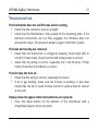
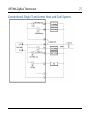
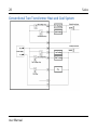
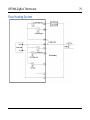
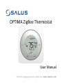
OPTIMA ZigBee Thermostat User Manual For other language versions, please visit: www.salusinc.com ii Salus SAFETY INSTRUCTIONS Please read these instructions carefully before installing and using the OPTIMA thermostat, and keep this guide in a safe place for future reference. • Follow all local and electricity supplier regulations regarding the installation or replacement of a thermostat. An authorized, qualified installer may be required. • Do not connect any of the terminals to the 110/220 VAC supply. The OPTIMA thermostat uses two AA batteries or a 24 VAC power source. • Do not cover any of the vents on the thermostat. • Do not install this unit at an altitude over 2000 meters. • Do not place the unit in a bathroom or area of excessive moisture. Do not allow the unit to get wet. This device serves as a temperature control system only in dry, closed living and office spaces. • Do not expose the unit to temperatures below 5°C or above 40°C, humidity above 80%, or pollution above level 2. User Manual OPTIMA ZigBee Thermostat iii • Do not expose the unit to voltage fluctuations more than +/10%. • Do not use solvents or aggressive cleaning agents. A dry, soft cloth is recommended. The manufacturer accepts no responsibility for damage caused by not following these instructions. iv Salus CONTENTS IN THE BOX 1 CONTROLS AND DISPLAY 2 BUTTONS HOME SCREEN 2 4 INSTALLING THE THERMOSTAT 6 TOOLS TURN OFF POWER TO HVAC SYSTEM DETERMINE WIRING CONFIGURATION REMOVE OLD THERMOSTAT INSTALL MOUNTING PLATE ATTACH WIRING INSTALL BATTERIES INITIAL CONFIGURATION ATTACH THERMOSTAT TO MOUNTING PLATE TURN POWER BACK ON TO THE HVAC SYSTEM CONFIGURE THERMOSTAT User Manual 7 7 7 9 9 10 10 11 12 12 12 OPTIMA ZigBee Thermostat v USING THE THERMOSTAT 13 CHANGING THE SET POINT TEMPERATURE SETTING A HOLD SET POINT TEMPERATURE CHANGING THE OPERATING MODE TURNING ON THE FAN 13 14 15 15 CONFIGURING THE THERMOSTAT 16 CONFIGURATION MENUS RESET TO DEFAULTS 16 21 SPECIFICATIONS 22 TROUBLESHOOTING 23 SALUS WARRANTY 23 APPENDIX A – WIRING DIAGRAMS 26 TERMINAL DEFINITIONS CONVENTIONAL SINGLE TRANSFORMER HEAT AND COOL SYSTEM CONVENTIONAL TWO TRANSFORMER HEAT AND COOL SYSTEM 26 27 28 vi Salus FLOOR HEATING SYSTEM SINGLE TRANSFORMER HEAT PUMP SYSTEM TWO TRANSFORMER HEAT PUMP SYSTEM 29 30 31 APPENDIX B – REGULATORY STATEMENTS 32 FCC STATEMENTS FCC AND INDUSTRY CANADA INDUSTRY CANADA 32 33 33 User Manual OPTIMA ZigBee Thermostat 1 IN THE BOX Thermostat with Mounting Plate Wire Labels Trim plate 2 x AA alkaline batteries User’s Manual Screws and Anchors Quick Start Guide 2 Salus CONTROLS AND DISPLAY Buttons Slider Ring –/Previous Fan/Hold /Back Reset (on bottom of unit) User Manual +/Next Mode /Enter OPTIMA ZigBee Thermostat Button Slider Ring –/Previous +/Next FAN/HOLD /Back MODE /Enter Reset 3 Regular Mode Slide clockwise to increment or counterclockwise to decrement values. Tap to decrement values. Tap to Increment values. Select fan mode. Engage HOLD when adjusting temperature. Select operating mode. Installation Mode Display next/previous option. Display previous option. Display next option. Back to previous menu. Select displayed option. Reset to default state. 4 Salus Home Screen Heat and Cool Icons Radio Icon Low Battery Label Area Day of Week & Time Room Temperature Fan Indicator Set Point Temperature System Mode Fan Mode The Home screen is the main display screen. If you do not press any buttons for 3 seconds, the thermostat will return to the Home screen. User Manual OPTIMA ZigBee Thermostat Indicator Heat and Cool Icons Radio Icon Low Battery Label Area Day of Week & Time Room Temp. Fan Indicator Set Point Temperature 5 Meaning Indicates HVAC / heat-pump state. – Air Conditioner is on or Cooling – Furnace is on or Heating blank – No HVAC / heat pump activity Indicates when the thermostat is connected to a smart home system Indicates when the 2 AA batteries need to be replaced Displays thermostat state, menu and options (see Using the Thermostat and Configuring the Thermostat sections for more info) Displays day of the week and time in 12- or 24-hour format Displays the room temperature at the thermostat Indicates Fan state. – Fan ON blank – Fan OFF Displays the set point temperature for the selected system mode 6 Salus Indicator System Mode Fan Mode Meaning Operating mode for the HVAC / heat pump system Off – System is OFF Cool – AC or Cooling mode Heat – Furnace or Heating mode EmHeat – Emergency Heat mode (heat pump only) Manual Fan Override Auto – Fan based on Heat / Cool activity On – Fan is always ON INSTALLING THE THERMOSTAT There are five basic steps to installing the thermostat • Turn off power to the HVAC system • Determine the wiring configuration • Install new thermostat, removing old thermostat and/or mounting the trim plate if required • Turn power back on to the HVAC system • Configure the new thermostat User Manual OPTIMA ZigBee Thermostat 7 Tools You may need the following tools to install the Optima thermostat. • Smartphone or camera to take pictures • Phillips or flathead screwdriver • Small screwdriver to disconnect wires from old terminals • Pencil • Drill with 3/16” bit (only if you cannot mount the thermostat using the existing holes) Turn off power to HVAC system Locate the HVAC breaker in the electrical panel and turn OFF the circuit. In some regions, there may be a switch located near the HVAC system. Determine wiring configuration If the OPTIMA thermostat is being installed in a new system, refer to Appendix A for the proper wiring configuration and skip to the Install Mounting Plate section. 8 Salus When replacing an existing thermostat, the goal is to replicate the wiring of the old thermostat on the OPTIMA thermostat. • Remove the old thermostat to expose the wiring terminals. • Take a picture of the wiring for future reference. • Note the terminals attached to each wire and attach the matching label to the ends of the wires. • If the terminals are unmarked on the old thermostat, you may need to go to the furnace / air conditioner / heat pump to determine the terminals for each wire color. Use the table to the right to keep track. User Manual HP Non-‐HP R RC -‐-‐ RH C C L -‐-‐ Y1 Y1 Y2 Y2 W1 W1 O/B W2 G G Wire Color OPTIMA ZigBee Thermostat Remove Old Thermostat Remove the old thermostat from the wall, taking care not to allow the wiring to fall inside the wall. 9 TIP: Wrap the wire ends around a long stick, such as a pencil to keep the wires from falling into the wall. Install Mounting Plate Remove the mounting plate from the back of the Optima thermostat. Use the included wall anchors and screws to attach the mounting plate to the wall, making sure the wires run through the center opening. If there is space on the wall from the old thermostat that needs to be covered, insert the trim plate between the mounting plate and the wall, and mount both plates using the same anchors and screws. The trim plate can be oriented vertically or horizontally for proper coverage. 10 Attach Wiring Before attaching the wires, match the wire (using the labels) to its corresponding terminal. Refer to the picture of the wiring taken earlier if necessary. • Open the terminal by lifting the latch up. • Push each wire into the hole of the terminal and push the latch down to secure the wire. Install Batteries Insert the alkaline batteries into the back of the thermostat. Make sure the polarities of the batteries are correct. Alkaline batteries are recommended as the Low Battery sensor is tuned to alkaline batteries. Warning: Do not mix old and new batteries. Do not mix different chemistries (Alkaline, Ni-Cad, Lithium, etc.) User Manual Salus OPTIMA ZigBee Thermostat 11 Initial Configuration After inserting the batteries, the display will flash all the segments, followed by the firmware version number, then display US / CA with a blinking US. When configuring the thermostat, select the desired option by pressing the + or – button or using the slider ring to cause the desired value to blink, then pressing MODE. Using the table below, select your country, then your type of system. Blinking Value US CA Description United States – Configures thermostat for use in the US. Canada – Configures thermostat for use in Canada HP NON-HP Heat Pump Non Heat Pump – Gas, electric, or oil heat O B Heat Pump with O reverse valve Heat Pump with B reverse valve HE HG Electric Heat Gas or Oil Heat After the initial configuration, the thermostat will display the Home Screen, at which point it is ready to be attached to the Mounting Plate. 12 Salus Attach Thermostat To Mounting Plate Attach the thermostat to the Mounting Plate by aligning the connector pins and the plastic retention posts and pushing the thermostat onto the mounting plate. Make sure the connector pins are not bent and that the thermostat is fully seated on the mounting plate. Turn Power Back On To The HVAC System Go to the breaker box or furnace switch and turn the HVAC system back on. Configure Thermostat The thermostat can now be used as a local manual thermostat, but to enable the enhanced features, additional settings need to be configured. See the Configuring the Thermostat section for more details. User Manual OPTIMA ZigBee Thermostat 13 USING THE THERMOSTAT The OPTIMA thermostat offers basic functions from the local controls, such as changing the Set Point and turning on the fan. To conserve energy and minimize distractions at night, the display backlight automatically turns off if no buttons are pressed within 10 seconds. Changing the Set Point Temperature There are two ways to change the set point temperature, using the + or – buttons, or the slider ring. From the Home Screen, the first press of the + button will move the set point temperature to the large temperature display and blink the display. Each press afterwards will increase the set point by 0.5 degrees. If the set point is not changed further within three (3) seconds, the flashing value becomes the new set point temperature and the screen returns to the Home Screen. Similarly, from the Home Screen, the first press of the – button will move and blink the set point temperature, and each press afterwards will decrease the set point by 0.5 degrees. 14 Salus Sliding your finger along any part of the slider ring (the silver circular ring around the screen) other than the MODE and FAN/HOLD locations will also change the set point temperature. To increase the set point, slide clockwise on the circular ring. To decrease the set point, slide counterclockwise. While sliding, you can slide through the MODE and FAN/HOLD locations. Lift your finger from the ring when the desired set point is displayed and it will be saved when the blinking stops and the screen returns to the Home Screen. The set point temperature will stay at the selected value until changed by the buttons or by the connected smart home system. Setting a HOLD Set Point Temperature If you would like to have the OPTIMA thermostat ignore set point temperature changes from the connected home system, you can place the thermostat on HOLD. To do this, select the desired set point temperature and press the FAN/HOLD button while the set point temperature is blinking. The word HOLD will appear in the Label Area to indicate the HOLD state. User Manual OPTIMA ZigBee Thermostat 15 To remove the HOLD state, simply change the set point temperature using the buttons or the slider ring. The thermostat will now accept set point changes from the connected home system. Changing the Operating Mode To change the operating mode of the system, simply touch the MODE button to select between the following: • Off – The thermostat will not call for heat or cooling. • Cool – The thermostat will call for cooling if the room temperature is above the Cool set point. • Heat – The thermostat will call for heat if the room temperature is below the Heat set point. • Emergency Heat – For heat pumps only. The thermostat will call for heat from the secondary heating unit instead of the heat pump if the room temperature is below the Heat set point. Turning On the Fan When you want the fan to be on regardless of the heating or cooling state, press the FAN/HOLD button when the Home Screen is displayed. 16 Salus The Fan Mode will change to indicate the current mode of the fan, and the Fan Icon will appear when the fan is turned on. There will be a slight delay between selecting Fan On mode and the fan turning on. Press the FAN/HOLD button again to put the fan back into Auto mode, under the control of the thermostat. CONFIGURING THE THERMOSTAT Configuration Mode is for experienced or authorized installers To enter Configuration Mode, press MODE for 3 seconds. The display will clear and show a blinking CLOCK in the Label Area. In Configuration Mode, after 20 seconds of inactivity, the thermostat will exit Configuration Mode and return to the Home Screen. Configuration Menus Following are the functions that can be configured on the OPTIMA thermostat. When a sub-menu option is selected, the thermostat will return to the sub-menu title to indicate that the option has been stored. The + or – buttons can be used to select another menu item at the same level. To return to a higher-level menu item at any time, press the FAN/HOLD button. User Manual OPTIMA ZigBee Thermostat 17 CLOCK Time Zone – default is PST US NST – Newfoundland Time Zone AST – Atlantic Time Zone EST – Eastern Time Zone CST – Central Time Zone MST – Mountain Time Zone PST – Pacific Time Zone AKST – Alaska Time Zone HST – Hawaii Time Zone √ √ √ √ √ √ CA √ √ √ √ √ √ √ √ 12/24 hour format 12 hr - Use AM/PM indicators (default) 24 hr - Use 24 hour notation Time Set current time in hours and minutes (defaults to midnight) Date Set month, day, and year (defaults to Jan 1, 2014) 18 Salus Daylight Savings Time ON – Daylight Savings Time is observed (default) OFF – Daylight Savings Time is NOT observed SETTINGS Country – sets operating limits and defaults for time zone and temperature units US – United States values CA – Canadian values HVAC Type HP – Heat Pump O – O reverse valve (default) B – B reverse valve NON-HP – Electric, Gas, or Oil heat FAN HG – Fan functionality for gas heating (default) FAN HE – Fan functionality for electric or oil heating Temperature Units ºF – Use Fahrenheit units for temperature (US default) ºC – Use Celsius/Centigrade units for temperature (CA default) User Manual OPTIMA ZigBee Thermostat 19 Offset – should the temperature sensor need calibration This value is added to the sensed temperature to determine the room temperature. Range: ±7ºF in 1 degree increments ±4ºC in 0.5 degree increments Default: 0 degrees Span – temperature variance before taking action This value determines the amount of temperature variation allowed before calling for heat or cooling. Example: a span of 1ºF with a set point of 70ºF will allow the room temperature to swing between 69ºF and 71ºF without taking action. Range: 0.5 – 2.0ºF in 0.5 degree increments 0.25 – 1.0ºC in 0.25 degree increments Default: 0.5ºF (US), 0.25ºC (CA) PAIR This menu item allows the Optima ZigBee thermostat to be connected to a compatible connected home system. Pairing the OPTIMA to a connected home system is a coordinated effort between the two systems. Following are general steps for the 20 Salus pairing process. Check with your connected home system procedures for more details. • Prepare connected home system to add a thermostat. • Go to the PAIR menu item on the OPTIMA thermostat. • Press MODE to select pairing mode. Display will show WILL PAIR. • Press MODE again to enter pairing mode. Display will show the number 10 and Pairing. • Wait for the connected home system to recognize the thermostat. The thermostat will blink IDENTIFY and return to the Home Screen when the thermostat has been added to the system. The blinking IDENTIFY will go away after 3 minutes. UPDATE This menu item initiates a check for new firmware on the connected home system and updates the firmware automatically if one is found. User Manual OPTIMA ZigBee Thermostat 21 Reset To Defaults The RESET button is located on the bottom surface of the OPTIMA and can only be accessed with a pin. When pressed, the RESET button will return the OPTIMA to default values as follows: Time DST Date 12/24 hr Midnight ON Jan. 1, 2014 12 System Type Mode Fan Heat Set Point Cool Set Point Span Offset Non-HP: Fan HG Heat Auto 20 °C / 68 °F 26 °C / 79 °F 0.25 °C / 0.5 °F 0° RESET WILL NOT CLEAR: • Country and related settings (time zone and temperature units) • Networking information • HVAC system type After reset, the OPTIMA will look for the hub or gateway from before the reset. The OPTIMA will only connect to another network when the PAIR function is performed. 22 Salus SPECIFICATIONS Temperature units Operating temperature Indoor temperature measurement range RF frequency RF range Protocol Battery Power Battery Life A/C power Size Weight °C or °F 32-113 °F (0-45 °C) 32-99 °F (0-37 °C) 2.40-2.48 GHz Up to 1300 ft (400 m) line of sight ZigBee – Home Automation 1.2 2 x AA Alkaline battery 18 months under normal usage 18-30 VAC at R and C terminals 4.2” (L) x 4.2” (W) x 1.1” (H) 10.7cm (L) x 10.7cm (W) x 2.9cm (H) 0.76 lb (345 g) User Manual OPTIMA ZigBee Thermostat 23 TROUBLESHOOTING The thermostat does not call for heat and/or cooling. • Check that the connector pins are straight • Check that the thermostat is fully seated on the mounting plate. If the terminal connections are not fully engaged, the firmware does not activate the relays. This prevents power surges to the HVAC system. The heat and cooling are reversed. • Check that the thermostat is configured properly, Heat Pump (HP) or non-HP. If Heat Pump, Check that the O/B configuration is correct. • Check that the wiring is correct, especially the Y and W wires. If Heat Pump, Check that the O/B wire is correct. The fan does not turn on. • Check that the wiring is correct, especially the G wire. • If oil or gas heating, make sure the furnace is working. in Gas Heat mode (HG), the fan is under furnace control to avoid a blast of cold air at the start. Display does not appear when low batteries are replaced. • Press the Reset button on the bottom of the thermostat with a straightened paper clip or pen point. 24 Salus SALUS WARRANTY Salus Controls Inc. (“Salus”) warrants that for a period of two (2) years (“Warranty Period”) from the date of purchase by the consumer (“Customer”), this device, excluding batteries (“Product”), shall be free of defects in materials and workmanship under normal use and service in accordance with all supplied instructions. During the warranty period, Salus shall, at its option, repair or replace any defective Products, at no charge for the device. Any replacement and/or repaired devices are warranted for the remainder of the original Warranty Period or ninety (90) days, whichever is longer. This warranty does not cover removal or reinstallation costs. This warranty does not apply to any Product (i) which has been modified, repaired, or altered, except by Salus or an authorized Salus representative, (ii) which has not been maintained in accordance with any handling or operating instructions supplied by Salus, or (iii) which has been subjected to unusual physical or electrical stress, misuses, abuse, negligence or accidents. This warranty is the only express warranty Salus makes for the Product. Any implied warranties, including warranties of merchantability or fitness for a particular purpose, are limited to the Warranty Period or the shortest period allowed by law. SALUS SHALL NOT BE LIABLE FOR ANY LOSS OR DAMAGE OF ANY KIND, INCLUDING ANY SPECIAL, INCIDENTAL OR CONSEQUENTIAL DAMAGES RESULTING, DIRECTLY OR INDIRECTLY, FROM ANY BREACH OF ANY WARRANTY, EXPRESS OR IMPLIED, OR ANY OTHER FAILURE OF THIS PRODUCT. Some states and provinces do not allow the exclusion or limitation of incidental or consequential damages, or limitation on the User Manual OPTIMA ZigBee Thermostat 25 duration of implied warranties of merchantability or fitness, so these exclusions or limitations may not apply to you. No oral or written information or advice given by Salus or a Salus-authorized representative shall modify or extend this warranty. If any term is held to be illegal or unenforceable, the legality or enforceability of the remaining terms shall not be affected or impaired. Customer’s sole and exclusive remedy under this limited warranty is product repair or replacement as provided herein. If a Product under warranty is defective, the Customer may: • contact the party (“Seller”) from which the Customer purchased the Product to obtain an equivalent replacement product after the Seller has determined that the Product is defective and the Customer is eligible for a replacement, or, • contact Salus Service at 4700 Duke Drive, Suite 200, Mason, OH 45040, to determine whether the device qualifies for a replacement. If a replacement is warranted and is shipped prior to the return of the device under warranty, a credit card is required and a hold may be placed on the Customer’s credit card for the value of the replacement until the returned device is verified as eligible for replacement, in which case, the Customer’s credit card will not be charged. This warranty gives you specific legal rights, and you may also have other rights that vary from jurisdiction to jurisdiction. If you have any questions regarding this warranty, please write Salus at: 123 Townsend St. Level LL2 San Francisco, CA 94107 26 APPENDIX A – WIRING DIAGRAMS Terminal Definitions User Manual Salus OPTIMA ZigBee Thermostat 27 Conventional Single Transformer Heat and Cool System 28 Conventional Two Transformer Heat and Cool System User Manual Salus OPTIMA ZigBee Thermostat 29 Floor Heating System 30 Single Transformer Heat Pump System User Manual Salus OPTIMA ZigBee Thermostat 31 Two Transformer Heat Pump System 32 Salus APPENDIX B – REGULATORY STATEMENTS FCC Statements WARNING: Changes or modifications to this unit not expressly approved by the party responsible for compliance could void the user’s authority to operate the equipment. This device complies with Part 15 of the FCC Rules. Operation is subject to the following two conditions: (1) this device may not cause harmful interference, and (2) this device must accept any interference received, including interference that may cause undesired operation. NOTE: This equipment has been tested and found to comply with the limits for a Class B digital device, pursuant to Part 15 of the FCC Rules. These limits are designed to provide reasonable protection against harmful interference in a residential installation. This equipment generates, uses and can radiate radio frequency energy, and if not installed and used in accordance with the instructions, may cause harmful interference to radio communications. However, there is no guarantee that interference will not occur in a particular installation. If this equipment does cause harmful interference to radio or television reception, which can be determined by turning the equipment off and on, the user is encouraged to try to correct the interference by one or more of the following measures: • Reorient or relocate the receiving antenna. • Increase the separation between the equipment and receiver. • Connect the equipment into an outlet on a circuit different from that to which the receiver is connected. • Consult the dealer or an experienced radio/TV technician for help. User Manual OPTIMA ZigBee Thermostat 33 FCC and Industry Canada RF Radiation Exposure statement: This equipment complies with FCC and Industry Canada RF radiation exposure limits set forth for an uncontrolled environment. This equipment should be installed and operated with a minimum distance of 20 centimeters between the antenna and all persons. Industry Canada Under Industry Canada regulations, this radio transmitter may only operate using an antenna of type and maximum (or lesser) gain approved for the transmitter by Industry Canada. To reduce potential radio interference to other users, the antenna type and its gain should be so chosen that the equivalent isotropically radiated power (e.i.r.p.) is not more than that necessary for successful communication. This device complies with Industry Canada licence-exempt RSS standard(s). Operation is subject to the following two conditions: (1) this device may not cause interference, and (2) this device must accept any interference, including interference that may cause undesired operation of the device. Le présent appareil est conforme aux CNR d'Industrie Canada applicables aux appareils radio exempts de licence. L'exploitation est autorisée aux deux conditions suivantes : (1) l'appareil ne doit pas produire de brouillage, et (2) l'utilisateur de l'appareil doit accepter tout brouillage radioélectrique subi, même si le brouillage est susceptible d'en compromettre le fonctionnement. Salus Controls Inc. 123 Townsend St. Level LL2 San Francisco, CA 94107 Version 1.0