1
99 Washington Street
Melrose, MA 02176
Phone 781-665-1400
Toll Free 1-800-517-8431
Visit us at www.TestEquipmentDepot.com
Model 7710 Multiplexer Card
User’s Guide
PA-847 Rev. B / 8-03
A GREATER MEASURE OF CONFIDENCE
.
Test Equipment Depot - 800.517.8431 - 99 Washington Street Melrose, MA 02176 - TestEquipmentDepot.com
Safety Precautions
The following safety precautions should be observed before using
this product and any associated instrumentation. Although some instruments and accessories would normally be used with non-hazardous voltages, there are situations where hazardous conditions
may be present.
This product is intended for use by qualified personnel who recognize shock hazards and are familiar with the safety precautions required to avoid possible injury. Read and follow all installation,
operation, and maintenance information carefully before using the
product. Refer to the manual for complete product specifications.
If the product is used in a manner not specified, the protection provided by the product may be impaired.
The types of product users are:
Responsible body is the individual or group responsible for the use
and maintenance of equipment, for ensuring that the equipment is
operated within its specifications and operating limits, and for ensuring that operators are adequately trained.
Operators use the product for its intended function. They must be
trained in electrical safety procedures and proper use of the instrument. They must be protected from electric shock and contact with
hazardous live circuits.
Maintenance personnel perform routine procedures on the product
to keep it operating properly, for example, setting the line voltage
or replacing consumable materials. Maintenance procedures are described in the manual. The procedures explicitly state if the operator
may perform them. Otherwise, they should be performed only by
service personnel.
Service personnel are trained to work on live circuits, and perform
safe installations and repairs of products. Only properly trained service personnel may perform installation and service procedures.
Keithley products are designed for use with electrical signals that
are rated Measurement Category I and Measurement Category II, as
described in the International Electrotechnical Commission (IEC)
Standard IEC 60664. Most measurement, control, and data I/O signals are Measurement Category I and must not be directly connected to mains voltage or to voltage sources with high transient overvoltages. Measurement Category II connections require protection
for high transient over-voltages often associated with local AC
mains connections. Assume all measurement, control, and data I/O
connections are for connection to Category I sources unless otherwise marked or described in the Manual.
Exercise extreme caution when a shock hazard is present. Lethal
voltage may be present on cable connector jacks or test fixtures. The
American National Standards Institute (ANSI) states that a shock
hazard exists when voltage levels greater than 30V RMS, 42.4V
peak, or 60VDC are present. A good safety practice is to expect
that hazardous voltage is present in any unknown circuit before
measuring.
Operators of this product must be protected from electric shock at
all times. The responsible body must ensure that operators are prevented access and/or insulated from every connection point. In
some cases, connections must be exposed to potential human contact. Product operators in these circumstances must be trained to
protect themselves from the risk of electric shock. If the circuit is
capable of operating at or above 1000 volts, no conductive part of
the circuit may be exposed.
Do not connect switching cards directly to unlimited power circuits.
They are intended to be used with impedance limited sources.
NEVER connect switching cards directly to AC mains. When connecting sources to switching cards, install protective devices to limit fault current and voltage to the card.
Before operating an instrument, make sure the line cord is connected to a properly grounded power receptacle. Inspect the connecting
cables, test leads, and jumpers for possible wear, cracks, or breaks
before each use.
When installing equipment where access to the main power cord is
restricted, such as rack mounting, a separate main input power disconnect device must be provided, in close proximity to the equipment and within easy reach of the operator.
For maximum safety, do not touch the product, test cables, or any
other instruments while power is applied to the circuit under test.
ALWAYS remove power from the entire test system and discharge
any capacitors before: connecting or disconnecting cables or jumpers, installing or removing switching cards, or making internal
changes, such as installing or removing jumpers.
Do not touch any object that could provide a current path to the common side of the circuit under test or power line (earth) ground. Always
make measurements with dry hands while standing on a dry, insulated
surface capable of withstanding the voltage being measured.
The instrument and accessories must be used in accordance with its
specifications and operating instructions or the safety of the equipment may be impaired.
Do not exceed the maximum signal levels of the instruments and accessories, as defined in the specifications and operating information, and as shown on the instrument or test fixture panels, or
switching card.
When fuses are used in a product, replace with same type and rating
for continued protection against fire hazard.
Chassis connections must only be used as shield connections for
measuring circuits, NOT as safety earth ground connections.
If you are using a test fixture, keep the lid closed while power is applied to the device under test. Safe operation requires the use of a
lid interlock.
Test Equipment Depot - 800.517.8431 - 99 Washington Street Melrose, MA 02176 - TestEquipmentDepot.com
5/03
If a
screw is present, connect it to safety earth ground using the
wire recommended in the user documentation.
The ! symbol on an instrument indicates that the user should refer to the operating instructions located in the manual.
The
symbol on an instrument shows that it can source or measure 1000 volts or more, including the combined effect of normal
and common mode voltages. Use standard safety precautions to
avoid personal contact with these voltages.
The
frame.
symbol indicates a connection terminal to the equipment
The WARNING heading in a manual explains dangers that might
result in personal injury or death. Always read the associated information very carefully before performing the indicated procedure.
The CAUTION heading in a manual explains hazards that could
damage the instrument. Such damage may invalidate the warranty.
Instrumentation and accessories shall not be connected to humans.
To maintain protection from electric shock and fire, replacement
components in mains circuits, including the power transformer, test
leads, and input jacks, must be purchased from Keithley Instruments. Standard fuses, with applicable national safety approvals,
may be used if the rating and type are the same. Other components
that are not safety related may be purchased from other suppliers as
long as they are equivalent to the original component. (Note that selected parts should be purchased only through Keithley Instruments
to maintain accuracy and functionality of the product.) If you are
unsure about the applicability of a replacement component, call a
Keithley Instruments office for information.
To clean an instrument, use a damp cloth or mild, water based
cleaner. Clean the exterior of the instrument only. Do not apply
cleaner directly to the instrument or allow liquids to enter or spill
on the instrument. Products that consist of a circuit board with no
case or chassis (e.g., data acquisition board for installation into a
computer) should never require cleaning if handled according to instructions. If the board becomes contaminated and operation is affected, the board should be returned to the factory for proper
cleaning/servicing.
Before performing any maintenance, disconnect the line cord and
all test cables.
Test Equipment Depot - 800.517.8431 - 99 Washington Street Melrose, MA 02176 - TestEquipmentDepot.com
Keithley Instruments, Inc.
28775 Aurora Road
Cleveland, Ohio 44139
(440) 248-0400
Fax: (440) 248-6168
www.keithley.com
Model 7710 Multiplexer Card
User’s Guide
Introduction
NOTE
The Model 7710 will operate properly when installed in one of the following
Model 27xx instruments:
Model 2700 – Equipped with B05 (or later) firmware
Model 2701 – Equipped with A01 (or later) firmware
Model 2750 – Equipped with A04 (or later) firmware
The Model 7710 is a 20-channel differential multiplexer card with the following features:
•
•
•
•
•
•
WARNING
Fast actuating, long life solid state relays.
DC and AC voltage measurement.
2-wire or 4-wire measurements (automatically pairs relays for four wire measurements —
n + 10).
Temperature applications (RTD, thermistor, thermocouple).
Built-in cold junction reference for TC temperature.
Plug-in screw terminal connections.
Before operating the Model 27xx with an accessory card, verify that the card is
properly installed and the mounting screws are tightly fastened. If the mounting screws are not properly connected, an electrical shock hazard may be
present.
Topics
Operating instructions............................................................................................... page 2
Card configuration .................................................................................................... page 2
Fast scanning .......................................................................................................... page 4
Fast scan using 7710 module with Model 2701 mainframe ..................................... page 4
Operating considerations........................................................................................ page 10
Low-ohms measurements ...................................................................................... page 10
Voltage measurements .......................................................................................... page 11
Insertion loss .......................................................................................................... page 12
Crosstalk................................................................................................................. page 12
Additional errors for 27xx switch systems .............................................................. page 12
Heat sink temperature measurements ................................................................... page 13
Card handling precautions...................................................................................... page 13
Card connections.................................................................................................... page 14
Wiring procedure .................................................................................................... page 15
Typical connections ................................................................................................ page 17
Connection log........................................................................................................ page 19
Calibration .............................................................................................................. page 21
Specifications ...................................................................................... end of User s Guide
PA-847 Rev. B / 8-03
Test Equipment Depot - 800.517.8431 - 99 Washington Street Melrose, MA 02176 - TestEquipmentDepot.com
Operating instructions
Before installing or removing a Model 77xx plug-in module, make sure the
Model 27xx power is turned off and disconnected from line power. Failure to
comply may result in incorrect operation and loss of Model 77xx EPROM data.
Topics
CAUTION
Switching card operation is covered in the Model 27xx User’s Manual. The Model 7710 operates
the same as the Model 7700 switching card with the following differences:
•
•
The Model 7710 has no amps channel. The Model 7700 has two amps channels.
The Model 7710 uses solid state opto-coupled FET relays. The Model 7700 uses latching
electromechanical relays. Solid state relays provide longer relay life and are up to six
times faster than the electromechanical types used in other switching modules.
WARNING
The system’s maximum voltage, including other switch modules and front
panel terminals, is limited to 60V peak-to-peak AC or DC between any terminal
and chassis, or any two terminals when the 7710 is installed. Exceeding these
levels creates a shock hazard and could cause damage to the card. Complete
specifications are located at the end of this User’s Guide.
WARNING
When a Model 7710 module is inserted into a Model 27xx, it is connected to
the front and rear inputs, as well as the other cards in the system, through the
instrument backplane. To prevent damaging the 7710 module or creating a
shock hazard, the entire test system and all of its inputs should be de-rated to
60V DC (42V rms).
Topics
Card configuration
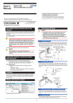
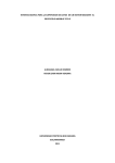
Figure 1 shows a simplified schematic diagram of the Model 7710 module. As shown, the
Model 7710 has channels that are grouped into two banks of ten channels (twenty channels
total). Backplane isolation is provided for each bank. Each bank includes separate cold junction
reference points. The first bank contains channels 1 through 10, while the second bank contains
channels 11 through 20. Each channel of the 20-channel multiplexer card is wired with separate
inputs for HI/LO providing fully isolated inputs.
Connections to DMM functions are provided through the card backplane connector.
Channels 21, 22, and 23 are configured automatically by the Model 27xx when using system channel operation. However, by using multiple channel operation (refer to Section 2 of the Model 27xx
User’s Manual), they can be manually configured.
For example, assume a 7710 module is installed in slot 1 of the mainframe and an external source
is connected to Card Source input. To connect the source to channel 11 only, multiple channel
operation must be used:
ROUT:OPEN:ALL
ROUT:MULT:CLOS (@111,123)
'Open all channels.
'Close channels 11 and 23.
2
Test Equipment Depot - 800.517.8431 - 99 Washington Street Melrose, MA 02176 - TestEquipmentDepot.com
Topics
For the above command sequence, the Digital Multimeter (DMM) of the Model 27xx will be electrically
isolated from the test circuit.
When using system channel operation for 4-wire measurements (including 4-wire ohms, RTD
temperature, Ratio, and Channel Average), the channels are paired as follows:
CH6 and CH16
CH2 and CH12
CH7 and CH17
CH3 and CH13
CH8 and CH18
CH4 and CH14
CH9 and CH19
CH5 and CH15
CH10 and CH20
Topics
CH1 and CH11
Figure 1
Simplified schematic of Model 7710
Card Source HI
LO
Cold junction
Ref x3
Channel 1
HI
LO
Channel 21
(see Note)
Backplane
isolation
(Channels 2-9)
HI
HI
Input
LO
Channel 10
LO
Cold junction
Ref x3
Channel 11
HI
LO
(Channels 12-19)
HI
Channel 20
Card Sense
LO
HI
LO
To Model
27xx
Backplane
Channel 22
(see Note)
Backplane
isolation
Topics
Channel 23
2-Pole (Closed)
4-Pole (Open)
(see Notes)
HI
Sense
LO
Notes:
Channels 21, 22, and 23 in this schematic refer
to the designations used for control and not actual
available channels.
Channels 21 and 22 can be individually
controlled using multiple channel operation
(ROUT:MULT commands) if the module is not
to be connected to the internal DMM.
For more information, see Section 2 of the
Model 27xx User’s Manual.
Topics
3
Test Equipment Depot - 800.517.8431 - 99 Washington Street Melrose, MA 02176 - TestEquipmentDepot.com
Fast scanning
Topics
Fast scanning is achieved by using the 7710 module (which has high-speed solid state FET relays)
with the Model 2701 mainframe. With mainframe speed settings optimized for DCV or ohms measurements, the Model 2701 can scan approximately twice as fast as the Models 2700 and 2750.
To achieve the fastest scan possible, use the following Model 27xx mainframe settings for the
scan:
VOLT:AVER:STAT OFF
‘ Disables filtering.
VOLT:DIG 4
‘ Sets display resolution to 4.5 digits.
VOLT:NPLC X
‘ Sets reading rate:
‘ where: X = 0.01 (2700 and 2750).
‘ X = 0.002 (2701)
SYST:AZER:STAT OFF
‘ Disables auto-zero.
SYST:LSYN OFF
‘ Disables line synchronization.
TRIG:DEL 0
‘ Sets trigger delay to 0 seconds.
FORM:DATA ASCII
‘ Formats data as an ASCII string (N/A for 2701).
FORM:ELEM READ
‘ Returns each reading with units only.
CALC3:OUTP OFF
‘ Disables limit outputs.
CALC3:LIM1:STAT OFF
‘ Disables limit 1 test.
DISP:ENAB OFF
‘ Turns off display.
DISP:ENAB ON
‘ Turns on display.
Topics
When finished with the scan, the display can be turned back on with the following command:
Fast scan using 7710 module with Model 2701 mainframe
The following Visual Basic (VB) Version 6 program demonstrates using the Model 7710 card and
Model 2701 mainframe to achieve fast scanning. It makes use of WinSocket control to communicate
with the Model 7701 mainframe. This User’s Guide is provided as a PDF file on the product information CD-ROM. From Acrobat Reader, the program code can be copied and pasted into Visual Basic.
Topics
4
Test Equipment Depot - 800.517.8431 - 99 Washington Street Melrose, MA 02176 - TestEquipmentDepot.com
’’’’’’’’’’’’’’’’’’’’’’’’’’’’’’’’’’’’’’’’’’’’’’’’’
’
’ This program is an example of configuring a simple DCV scan on the 7710 with a 2701 mainframe.
Topics
’ 7710 DCV FAST SCAN EXAMPLE FOR THE 2701 MODULE
’ This program acquires readings at a rate of 500/ sec.
’
’ Note that a Winsocket control in Visual Basic is being used to communicate with the 2701.
’’’’’’’’’’’’’’’’’’’’’’’’’’’’’’’’’’’’’’’’’’’’’’’’’’’’’’’’’’’’’’’’’’’’’’’’’’’’’’’’’’’’’’’’’’’
Const ScanList = "(@101:120)"
Dim TestRunning As Boolean
Dim DataReceived As Boolean
Dim DataSent As Boolean
Dim Data As String
’’’’’’’’’’’’’’’’’’’’’’’’’’’’’’’’’’’’’’’’’’’’’’’’’’’’’’’’’’’’’’’’’’’’’’
’ A Visual Basic function call when a Form (program window) is opened.
’’’’’’’’’’’’’’’’’’’’’’’’’’’’’’’’’’’’’’’’’’’’’’’’’’’’’’’’’’’’’’’’’’’’’’
Private Sub Form_Load()
TestRunning = False
’’’’’’’’’’’’’’’’’’’’’’’’’’’’’’’’’’’’’’’’’’’’’’’’’’’’’’’’’’’’’’’’
Topics
End Sub
’ These two functions exit the program and closes the winsocket.
’’’’’’’’’’’’’’’’’’’’’’’’’’’’’’’’’’’’’’’’’’’’’’’’’’’’’’’’’’’’’’’’
Private Sub ExitButton_Click()
Unload Me
End Sub
Private Sub Form_Unload(Cancel As Integer)
Cancel = MsgBox("Exit?", 20, "Exit Verify")
If Cancel = vbYes Then
Cancel = 0
CloseWinsocket
End If
End Sub
’’’’’’’’’’’’’’’’’’’’’’’’’’’’’’’’’’’’’’’’’’’’’’’’’’’’’’’’’’’’’’’’’’’’’’’’’’’’’’’’’’’’’’’
’ This function opens the Winsocket for communication with the 2701 ethernet mainframe.
’’’’’’’’’’’’’’’’’’’’’’’’’’’’’’’’’’’’’’’’’’’’’’’’’’’’’’’’’’’’’’’’’’’’’’’’’’’’’’’’’’’’’’’
Function ConnectTo2701() As Integer
5
Test Equipment Depot - 800.517.8431 - 99 Washington Street Melrose, MA 02176 - TestEquipmentDepot.com
Topics
Dim Time0 As Single
If txtAddress.Text = "" Then
Exit Function
End If
Topics
ConnectTo2701 = False
With Winsock1
.Protocol = sckTCPProtocol
.RemoteHost = txtAddress.Text
.RemotePort = 1394
.Connect
End With
' Check for proper connection.
Time0 = Timer
While Timer - Time0 < 10! And Winsock1.State <> sckConnected: DoEvents: Wend
If Winsock1.State <> sckConnected Then
’ Could not connect to 2701.
MsgBox "Cannot connect to " + LastAddress + "!", 48, "IP Connect Error"
ConnectTo2701 = False
Exit Function
End If
ConnectTo2701 = True
Topics
’ Connection to 2701 found.
End Function
’’’’’’’’’’’’’’’’’’’’’’’’’’’’’’’’’’’’’’’
’ Event to capture data from mainframe.
’’’’’’’’’’’’’’’’’’’’’’’’’’’’’’’’’’’’’’’
Private Sub Winsock1_DataArrival(ByVal bytesTotal As Long)
Winsock1.GetData Data, vbString, 50000
’Chr$(10) Or
If (Right$(Data, 1) = Chr$(10)) Then
Data = Left$(Data, Len(Data) - 1)
DataReceived = True
End If
End Sub
’’’’’’’’’’’’’’’’’’’’’’’’’’’’’’’’’’’’’’’’’’’’’’’’’’’’’’’’’’’’’’’’’’’’’’
’ QueryKI() retrieves data from the 2701 over the ethernet connection.
’’’’’’’’’’’’’’’’’’’’’’’’’’’’’’’’’’’’’’’’’’’’’’’’’’’’’’’’’’’’’’’’’’’’’’
’ Read Ethernet data.
6
Test Equipment Depot - 800.517.8431 - 99 Washington Street Melrose, MA 02176 - TestEquipmentDepot.com
Topics
Function QueryKI() As String
DataReceived = False
' Remain in loop until mainframe is finished sending data.
Topics
Do
DoEvents
Loop Until DataReceived
QueryKI = Data
' Return reading
End Function
’’’’’’’’’’’’’’’’’’’’’’’’’’’’’’’’’’’’’’’’’’’’’’’’’’’’’’’’’’’’’’’’’
’ This event occurs when host computer is finished sending data .
’’’’’’’’’’’’’’’’’’’’’’’’’’’’’’’’’’’’’’’’’’’’’’’’’’’’’’’’’’’’’’’’’
Private Sub Winsock1_SendComplete()
DataSent = True
End Sub
’’’’’’’’’’’’’’’’’’’’’’’’’’’’’’’’’’’’’’’’’’’’’’’’’’’’’’’’’’’’’’’
’ SendKI() sends data to the 2701 over the ethernet connection.
’’’’’’’’’’’’’’’’’’’’’’’’’’’’’’’’’’’’’’’’’’’’’’’’’’’’’’’’’’’’’’’
Sub SendKI(Cmd As String)
DataSent = False
Winsock1.SendData Cmd + Chr$(13)
Topics
’ Send command to mainframe and wait for data sent event.
Do
DoEvents
Loop Until DataSent
End Sub
’’’’’’’’’’’’’’’’’’’’’’’’’’’’’’’’’’’’’’’’’’’’
’ Close the winsocket if it is still opened.
’’’’’’’’’’’’’’’’’’’’’’’’’’’’’’’’’’’’’’’’’’’’
Private Sub CloseWinsocket()
If Winsock1.State <> sckClosed Then Winsock1.Close
End Sub
’’’’’’’’’’’’’’’’’’’’’’’’’’’’’’’’’’’’’’’’’’’’’’’’’’’’’’’’’’’’’’’’’’’’’
’ This function is called when the run button is pressed on the Form.
’’’’’’’’’’’’’’’’’’’’’’’’’’’’’’’’’’’’’’’’’’’’’’’’’’’’’’’’’’’’’’’’’’’’’
Private Sub RunTestButton_Click()
’ If a scan is not already running, begin a new scan.
7
Test Equipment Depot - 800.517.8431 - 99 Washington Street Melrose, MA 02176 - TestEquipmentDepot.com
Topics
'
If Not (TestRunning) Then
Topics
Call ScanDCV
End If
End Sub
’’’’’’’’’’’’’’’’’’’’’’’’’’’’’’’’’’’’’’’’’’’’’’’’’’’’’’’’’’’’’’’’’’’
’ Data is formatted to show one reading per line in reading window.
’’’’’’’’’’’’’’’’’’’’’’’’’’’’’’’’’’’’’’’’’’’’’’’’’’’’’’’’’’’’’’’’’’’
Private Sub Format_Readings(Resp As String)
Dim Out_str As String
Dim Ch As String
Dim i As Long
i = Len(Resp)
Out_str = ""
i = 1
While (i <= Len(Resp))
Ch = Mid(Resp, i, 1)
If (Ch = ",") Then
Ch = vbCrLf
Topics
End If
Out_str = Out_str + Ch
i = i + 1
Wend
Text1.Text = Out_str
End Sub
’’’’’’’’’’’’’’’’’’’’’’’’’’’’’’’’’’’’’’’’’’’’’’’’’’’’’’
’ This is the main function for the 7710 test program.
’’’’’’’’’’’’’’’’’’’’’’’’’’’’’’’’’’’’’’’’’’’’’’’’’’’’’’
Private Sub ScanDCV()
Dim NumReadings As Integer
Dim Resp As String
Dim Cmd As String
If Not (ConnectTo2701) Then
' Open connection to 2701.
Exit Sub
End If
TestRunning = True
Topics
8
Test Equipment Depot - 800.517.8431 - 99 Washington Street Melrose, MA 02176 - TestEquipmentDepot.com
’ Take 1024 readings.
Topics
NumReadings = 1024
Resp = Space$(80)
Cmd = Space$(80)
’ Configure the instrument for scanning DCV.
’
SendKI ("*RST")
' Put instrument in known state.
SendKI ("FORM:DATA ASCII")
' Format data as an ASCII string.
SendKI ("FORM:ELEM READ")
' Return the reading with units only.
SendKI ("SAMP:COUN " + CStr(NumReadings))
' Take 1024 readings.
SendKI ("FUNC 'VOLT:DC', " + ScanList)
' Set function to DCV.
SendKI ("VOLT:RANG 100," + ScanList)
' Set Range to 100V.
SendKI ("VOLT:AVER:STAT OFF," + ScanList)
' Read to 4 significant digits.
SendKI ("VOLT:NPLC 0.002," + ScanList)
' Set NPLC to 0.002.
SendKI ("CALC3:OUTP OFF")
' Turn off limit test.
SendKI ("SYST:LSYN OFF")
' Turn off line-sync.
SendKI ("DISP:ENAB OFF")
' Turn off display.
SendKI ("SYST:AZER:STAT OFF")
' Turn off auto-zero.
SendKI ("CALC3:LIM1:STAT OFF," + ScanList)
' Turn off limits.
SendKI ("TRIG:DEL 0")
' Set trigger delay to 0 seconds.
SendKI ("TRAC:CLE")
' Clear reading buffer.
SendKI ("ROUT:SCAN " + ScanList)
' Set scan list.
SendKI ("ROUT:SCAN:LSEL INT")
' Initiate scan.
SendKI ("*OPC?")
' Determines if mainframe is ready.
Topics
SendKI ("VOLT:DIG 4," + ScanList)
Resp = QueryKI()
SendKI ("INIT")
' Initiate scan and store in buffer.
SendKI ("*OPC?")
Resp = QueryKI()
' Wait for scan to complete.
SendKI ("ROUT:SCAN:LSEL NONE;*OPC?")
' Stop scan.
Resp = QueryKI()
SendKI ("TRACE:DATA?")
' Get readings from buffer.
Resp = QueryKI()
Format_Readings (Resp)
SendKI ("DISP:ENAB ON")
' Turn display back on.
CloseWinsocket
' Disconnect connection to mainframe.
End Sub
9
Test Equipment Depot - 800.517.8431 - 99 Washington Street Melrose, MA 02176 - TestEquipmentDepot.com
Topics
TestRunning = False
Operating considerations
For resistances in the normal range (>100Ω), the 2-wire method (Ω2) is typically used for ohms
measurements. For low-ohms (≤100 Ω), the signal path resistance in series with the DUT could be
high enough to adversely affect the measurement. Therefore, the 4-wire method ( Ω4) should be
used for low-ohms measurements. The following discussion explains the limitations of the 2-wire
method, and the advantages of the 4-wire method.
Topics
Low-ohms measurements
2-wire method
Resistance measurements in the normal range (>100Ω) are generally made using the 2-wire
method ( Ω2 function). The test current is forced through the test leads and the resistance being
measured (RS). The meter then measures the voltage across the resistance value accordingly.
The main problem with the 2-wire method, as applied to low-resistance measurements is the test
lead resistance (RLEAD) and the channel resistance (RCH). The sum of these resistances typically
lies in the range of 1.5 to 2.5Ω. Therefore, it is very difficult to obtain accurate 2-wire ohms measurements below 100 Ω.
Due to this limitation, the 4-wire method should be used for resistance measurements ≤100 Ω.
This method is explained as follows:
These measurements can be made using the Model 2750 Digital Multimeter. With this configuration, the test current (ITEST) is forced through the test resistance (RDUT) through one set of test
leads (RLEAD2 and RLEAD3), while the voltage (VM) across the Device Under Test (DUT) is measured through a second set of leads (RLEAD1 and RLEAD4) called the sense leads.
Topics
4-wire method
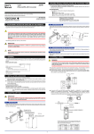
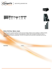
The 4-wire (Kelvin) connection method using the Ω4 function, as shown is Figure 2, is generally
preferred for low-ohms measurements. The 4-wire method cancels the effects of channel and test
lead resistance.
With this configuration, the resistance of the DUT is calculated as follows:
RDUT = VM / ITEST
where: ITEST is the sourced test current and VM is the measured voltage.
As shown in Figure 2, the measured voltage (VM) is the difference between V SHI and VSLO. The
equations at the bottom of Figure 2 show how test lead resistance and channel resistance is cancelled out of the measurement process.
Maximum test lead resistance (Model 2750)
Table 1 lists the maximum test lead resistance (R LEAD ), plus the resistance of the DUT (R DUT ). Note
that a larger test lead resistance can be tolerated with a smaller RDUT, as shown in the following
example:
Example:
10
Test Equipment Depot - 800.517.8431 - 99 Washington Street Melrose, MA 02176 - TestEquipmentDepot.com
Topics
If RDUT is 3Ω on the 10Ω range using the Ω4 (4-wire) function, then the maximum test lead resistance (RLEAD) can be 4Ω.
Table 1
Maximum test lead resistance (Model 2750)
Range
RLEAD
Ω4
RDUT
RLEAD
Ω4 Dry Circuit
RDUT
RLEAD
RDUT
1Ω
NA
NA
0Ω
1.2Ω
Overflow
Overflow
10Ω
0Ω
2Ω
0Ω
7Ω
3Ω
12Ω
Topics
Ω2
Figure 2
Low-ohms measurements using 4-wire method
2750 DMM with 7710 card
Ch11 Hi
VSHI
V
VM
ITEST
RCH11Hi
Sense Hi
RLEAD1
RCH1Hi
Input Hi
RLEAD2
Ch1 Hi
ITEST
ITEST
VSLO
RDUT
RCH1Lo
Input Lo
RLEAD3
RCH11Lo
Sense Lo
RLEAD4
Ch1 Lo
Ch11 Lo
Topics
Assumptions: Virtually no current flows in the high-impedance sense circuit due to
the high impedance of the voltmeter (VM). Therefore, the voltage
drops across Channel 11 and test leads 1 and 4 are negligible and
can be ignored.
The voltage drops across Channel 1 Hi (RCH1Hi) and test lead 2
(RLEAD2) are not measured by the voltmeter (VM).
where: VM is the voltage measured by the 2750.
RDUT = VM
ITEST is constant current sourced by the 2750 to the DUT.
ITEST
VM = VSHI - VSLO
VSHI = ITEST × (RDUT + RLEAD3 + RCH1Lo)
VSLO = ITEST × (RLEAD3 + RCH1Lo)
VSHI - VSLO = ITEST × [(RDUT + RLEAD3 + RCH1Lo) - (RLEAD3 + RCH1Lo)]
= ITEST × RDUT
= VM
Voltage measurements
High signal path resistance can also adversely affect AC voltage measurements on the 100V
range above 1kHz.
11
Test Equipment Depot - 800.517.8431 - 99 Washington Street Melrose, MA 02176 - TestEquipmentDepot.com
Topics
As previously explained, path resistance can adversely affect “Low-ohms measurements” (see
page 10). Series path resistance can also cause loading problems for DC voltage measurements
on the 100V, 10V, and 10mV ranges when the 10M Ω input divider is enabled.
Insertion loss
For the 7710 card, insertion loss is specified for a 50Ω AC signal source routed through the module to a 50Ω load. Signal power loss occurs as the signal is routed through the signal paths of the
module to the load.
Topics
Insertion loss is AC signal power lost between the input and the output. In general, as frequency
increases, insertion loss increases.
Insertion loss is expressed as dB magnitudes at specified frequencies. The specifications for insertion loss are provided in the “Specifications” at the end of this User’s Guide. (See INSERTION
LOSS in the “Specifications”.)
As an example, assume the following specifications for insertion loss:
<1dB @ 500kHz
<3dB @ 2MHz
1dB insertion loss is approximately 20% loss of signal power.
3dB insertion loss is approximately 50% loss of signal power.
As signal frequency increases, power loss increases.
NOTE
The insertion loss values used in the above example may not be the actual insertion
loss specifications of the Model 7710. The actual insertion loss specifications are
provided in the “Specifications” at the end of this User’s Guide.
Crosstalk
An AC signal can be induced into adjacent channel paths on the 7710 card. In general, crosstalk
increases as frequency increases.
Topics
For the 7710 card, crosstalk is specified for an AC signal routed through the module to a 50Ω load.
Crosstalk is expressed as a dB magnitude at a specified frequency. The specification for crosstalk
is provided in the “Specifications” at the end of this User’s Guide. (See CROSSTALK in the
“Specifications”.)
As an example, assume the following specification for crosstalk:
<-40dB @ 500kHz
-40dB indicates that crosstalk into adjacent channels is 0.01% of the AC
signal.
As signal frequency increases, crosstalk increases.
NOTE
The crosstalk values used in the above example may not be the actual crosstalk
specification of the Model 7710. The actual crosstalk specification is provided in the
“Specifications” at the end of this User’s Guide.
Additional errors for 27xx switch systems
Additional 27xx measurement errors and typical system scanning speeds are provided after the
first page of the “Specifications” on page 23. These measurement errors are to be added on to the
specifications of the Model 27xx mainframe being used in the switch system.
•
12
Test Equipment Depot - 800.517.8431 - 99 Washington Street Melrose, MA 02176 - TestEquipmentDepot.com
Topics
•
Notes 1, 2 and 3 (and tables) for “DC CHARACTERISTICS” pertain to additional errors
for high-ohms resistance measurements, voltage measurements, and temperature measurements.
The two tables for “SYSTEM SPEEDS” provide speed data for scanning. For the various
scan functions, the tables list the fundamental reading rate setting (in PLCs) and typical
speed (in readings per second) into and out of memory.
Heat sink temperature measurements
Topics
Measuring the temperature of a heat sink is a typical test for a system that has temperature measurement capability. However, the 7710 card cannot be used if the heat sink is being floated at a
dangerous voltage level (>60V). An example of such a test is shown in Figure 3.
In Figure 3, the heat sink is floating at 120V, which is the line voltage being input to a +5V regulator. The intention is to use channel 1 to measure the temperature of the heat sink, and use channel 2 to measure the +5V output of the regulator. For optimum heat transfer, the thermocouple
(TC) is placed in direct contact with the heat sink. This inadvertently connects the floating 120V
potential to the 7710 card. The result is 115V between channel 1 and channel 2 HI, and 120V
between channel 1 and chassis. These levels exceed the 60V limit of the card creating a shock
hazard and possibly causing damage to the card.
WARNING
The test in Figure 3 demonstrates how a dangerous voltage can unintentionally be applied to the 7710 card. Keep in mind that in any test where floating
voltages >60V are present, you must be careful not to apply the floating voltage to the card.
Figure 3
Example of an unsafe measurement practice
WARNING
DO NOT use the 7710 card to perform this type of test. It exceeds
the 60V limit creating a shock hazard and could cause damage to the
card. Excessive voltages:
The voltage differential between Ch 1 and Ch 2 HI is 115V.
The voltage differential between Ch 1 and Ch 2 LO (chassis) is 120V.
Thermocouple
Heat sink floating
at 120V.
Heat Sink
IN
120V
7710 Module
Ch 1
115V
OUT +5V
+5V
Regulator
Topics
Test Circuit
120V
Ch 2
5V
Ch 1 configured to measure TC temperature.
Ch 2 configured to measure 5V regulator output.
Card handling precautions
The solid state relays used on the 7710 card are static sensitive devices. Therefore, they can be
damaged by electrostatic discharge (ESD).
CAUTION
To prevent damage from ESD, only handle the module by the card edges. DO
NOT touch the backplane connector terminals. When working with the
quick-disconnect terminal blocks, DO NOT touch any circuit board traces or
other components. If working in a high-static environment, use a grounded
wrist strap when wiring the module.
13
Test Equipment Depot - 800.517.8431 - 99 Washington Street Melrose, MA 02176 - TestEquipmentDepot.com
Topics
Touching a circuit board trace may also contaminate it with body oils that may degrade the isolation
resistance between circuit paths, adversely affecting measurements. It is good practice to handle a
circuit board only by its edges.
Card connections
WARNING
Topics
Screw terminals on the switching module are provided for connection to DUT and external circuitry.
The Model 7710 uses quick-disconnect terminal blocks. A terminal block can be wired outside the
module and then plugged back in. These terminal blocks are rated for 25 connect/disconnects.
The information in this section is intended for qualified service personnel. Do
not attempt to perform this procedure unless qualified to do so.
Figure 4 shows how to access the screw terminals on the Model 7710. Channel designations for
the screw terminals are contained in Figure 5.
WARNING
Do not exceed the maximum specifications for the Model 7710 card. Refer to
the end of this User’s Guide for specifications.
Figure 4
Screw terminal access
Topics
UNLOCK
LOCK
Topics
14
Test Equipment Depot - 800.517.8431 - 99 Washington Street Melrose, MA 02176 - TestEquipmentDepot.com
Figure 5
Model 7710 screw terminal channel designations
CH2
CH3
CH4 CH5
CH6 CH7
CH8
CH9
CH10
L
H L
H L
H L
H L
H L
H L
H L
H L
H
CH4
L H
CH5
L H
CH6
L H
CH7 CH8
L H L H
CH9 CH10
L H L H
L H
CH1
L H L H
CH2 CH3
L H
CH4
L H
CH5
L H
CH6
L H L H
CH7 CH8
L H L H
CH9 CH10
L
H L
H
CH2 CH3
L H L H
CH11 CH12 CH13 CH14 CH15
L H L H L H L H L H
CH16 CH17 CH18 CH19 CH20
L H L H L H L H L H
L H L H L H L H L H
CH11 CH12 CH13 CH14 CH15
L H L H L H L H L H
CH16 CH17 CH18 CH19 CH20
L
H L
H L
H L
H L
H L
H L
H L
H L
H
CH12 CH13 CH14 CH15 CH16 CH17 CH18 CH19 CH20
Topics
L
H
CH11
SENSE SOURCE
CH1
L H
Topics
CH1
L
H
Wiring procedure
WARNING
The information in this section is intended for qualified service personnel
only. Do not attempt to perform this procedure unless qualified to do so.
Use the following procedure to wire the Model 7710 card. Make all connections using the correct
wire size (up to 20 AWG). Also, make sure to add supplementary insulation around the harness for
voltages above 42V peak (see Figure 7).
1.
2.
3.
4.
Make sure all power is discharged from the Model 7710 card.
Remove the card’s top cover to gain access to the screw terminals (see Figure 4).
If desired, pull the appropriate quick-disconnect terminal block off the card.
Using a small flat-blade screwdriver, loosen terminal screws and install wires as desired (refer to
Figure 6). Figure 7 shows connections to channels 1 and 2.
Topics
15
Test Equipment Depot - 800.517.8431 - 99 Washington Street Melrose, MA 02176 - TestEquipmentDepot.com
Figure 6
Proper procedure to remove terminal blocks
Topics
Step 1. Place flat-head screwdriver
under connector and gently
push up to loosen it.
Step 2. Pull connector directly up
with needle nose pliers.
CAUTION: DO NOT rock connector
from side to side. Damage
to the pins could result.
Topics
5.
6.
7.
8.
Plug the terminal block back into the card.
Route wire along wire-path and secure with cable ties as shown.
Fill in a copy of the connection log (Table 2 on page 18) and affix it to the module cover.
Close and lock cover.
NOTE
For maximum system performance, all measurement cables should be less than 3
meters.
Topics
16
Test Equipment Depot - 800.517.8431 - 99 Washington Street Melrose, MA 02176 - TestEquipmentDepot.com
Figure 7
Wire dressing
Topics
Cable Tie
Topics
Typical connections
The following examples show typical wiring connections for the following types of measurements:
•
•
•
•
Thermocouple connections, see Figure 8
Ω 2-wire and thermistor connections, see Figure 9
Ω 4-wire and RTD connections, see Figure 10
Voltage connections (DC or AC), see Figure 11
Topics
17
Test Equipment Depot - 800.517.8431 - 99 Washington Street Melrose, MA 02176 - TestEquipmentDepot.com
Figure 8
Thermocouple connections
Topics
HI
Channel 1
LO
(Channels 2-19)
Thermocouple
HI
Channel 20
LO
Figure 9
Ω 2-wire and thermistor connections
HI
Channel 1
LO
(Channels 2-19)
Resistor or
Thermistor
LO
Topics
HI
Channel 20
Topics
18
Test Equipment Depot - 800.517.8431 - 99 Washington Street Melrose, MA 02176 - TestEquipmentDepot.com
Figure 10
Ω 4-wire and RTD connections
Topics
HI
Resistor or
4-Wire RTD
Channel 1
LO
(Channels 2-9)
HI
Resistor or
4-Wire RTD
Channel 10
LO
HI
Channel 11
LO
(Channels 12-19)
HI
Channel 20
LO
DC Voltage
AC Voltage
Topics
Figure 11
Voltage connections (DC or AC)
HI
+
Channel 1
LO
(Channels 2-19)
HI
+
Channel 20
LO
Connection log
Make a copy of Table 2 and the WARNING and affix them to the cover of the Model 7710. Use this
to record connection information and channel descriptions as needed.
Topics
19
Test Equipment Depot - 800.517.8431 - 99 Washington Street Melrose, MA 02176 - TestEquipmentDepot.com
WARNING
Table 2
Connection log Model 7710
Channel
Color
Card Source
H
Card Sense
H
Topics
The system’s maximum voltage, including other switch modules and front
panel terminals, is limited to 60V peak-to-peak AC or DC between any terminal
and chassis or any two terminals when the 7710 is installed.
Description
L
L
CH1
H
CH2
H
CH3
H
CH4
H
CH5
H
CH6
H
CH7
H
CH8
H
CH9
H
CH10
H
CH11
H
CH12
H
CH13
H
CH14
H
CH15
H
CH16
H
CH17
H
CH18
H
CH19
H
CH20
H
L
L
L
L
L
L
L
L
L
Topics
L
L
L
L
L
L
L
L
L
L
L
Topics
20
Test Equipment Depot - 800.517.8431 - 99 Washington Street Melrose, MA 02176 - TestEquipmentDepot.com
Calibration
The following procedures calibrate the temperature sensors on the Model 7710 plug-in cards.
WARNING
The information in this section is intended only for qualified service personnel. Do not attempt these procedures unless you are qualified to do so.
Recommended test equipment
In order to calibrate the Model 7710, you will need equipment summarized in Table 3.
Table 3
Recommended equipment for Model 7710 calibration
Digital Thermometer:
18 to 23˚C, ±0.1˚C
Keithley 7797 Calibration/Extender Board
Extender board connections
The Model 7710 being calibrated should be connected to the 7797 Calibration/Extender Board,
and the extender board should then be installed in scanner Slot #1. Note that the module being
calibrated will be external to the Model 27xx to avoid card heating during calibration.
Model 7710 calibration
NOTE
Before calibrating the Model 7710, make sure that power has been removed from
the card for at least two hours to allow card circuitry to cool down. After turning on
the power during the calibration procedure, complete the procedure as quickly as
possible to minimize card heating that could affect calibration accuracy. Allow the
Model 27xx to warm up for at least two hours.
Front panel Model 7710 calibration
1. Connect the Model 7710 to the Model 7797 Calibration/Extender Board (see “Extender board connections” above).
2. With the power off, install the Model 7710/7797 combination in Slot 1 and select the rear inputs with the
INPUTS switch. Allow three minutes for thermal equilibrium.
3. Accurately measure and record the cold temperature of the Model 7710 card surface at the center of the
card with a digital thermometer.
4. Press in and hold the Model 27xx OPEN key while turning on the power.
5. Press SHIFT then TEST, and then display TEST:CALIB with the up or down range key. Press ENTER,
select RUN, and then enter the appropriate calibration code (default: 0027xx).
6. With NEW CODE? displayed, use the up or down range key to display N, and then press ENTER.
7. Using the up or down range key, select CARD at the CAL:RUN prompt, and then press ENTER.
8. Set the display value to the cold calibration temperature (°C) you measured in Step 3, then press ENTER
to complete Model 7710 calibration.
21
Test Equipment Depot - 800.517.8431 - 99 Washington Street Melrose, MA 02176 - TestEquipmentDepot.com
Remote Model 7710 calibration
1. Connect the Model 7710 to the 7797 Calibration/Extender Board (see “Extender board connections”).
2. With the power off, install the Model 7710/7797 combination in Slot 1, and select the rear inputs with the
INPUTS switch. Allow three minutes for thermal equilibrium.
3. Accurately measure and record the cold temperature of the Model 7710 card surface at the center of the
card.
4. Press in and hold the Model 27xx OPEN key while turning on the power.
5. Enable calibration by sending the :CODE command. For example, the default command is:
CAL:PROT:CODE 'KI0027xx'
6.Initiate calibration by sending the following command:
CAL:PROT:CARD1:INIT
7. Calibrate the Model 7710 with the following command:
CAL:PROT:CARD1:STEP0 <temp>
Here <temp> is the cold calibration temperature (˚C) measured in Step 3.
8. Send the following commands to save calibration and lock out calibration:
CAL:PROT:CARD1:SAVE
CAL:PROT:CARD1:LOCK
22
Test Equipment Depot - 800.517.8431 - 99 Washington Street Melrose, MA 02176 - TestEquipmentDepot.com
7710 20-Channel High-Speed/ Long-Life Differential
Multiplexer w/ Automatic CJC Specifications
GENERAL
20 CHANNELS: 20 channels of 2-pole relay input. All channels
configurable to 4-pole.
RELAY TYPE: Solid State Opto-Coupled FET
ACTUATION TIME: <0.5mS (100mA load)
FIRMWARE: Specified for Model 2700 Rev. B05, Model 2750 Rev.
A04, and Model 2701 Rev. A01.
CAPABILITIES
CHANNELS 1-20: Multiplex one of 20 2-pole or one of 10 4-pole
signals into DMM.
INPUTS
MAXIMUM SIGNAL LEVEL: 60V DC or 42V rms between
channel (1-20) HI and channel LO or between any channel HI or LO
to any other channel HI or LO, 100mA switched, 6W, 4.2VA
maximum.
COMMON MODE VOLTAGE: 300V DC or 300V rms (425V
peak) for AC waveforms between any terminal and chassis.
SAFETY: Conforms to European Union Directive 73/23/EEC
EN61010-1, CAT I.
EMC: Conforms with European Union Directive 89/336/EEC
EN61326-1.
CONTACT LIFE: >1010 operations at cold switching or max signal
level (guaranteed by design).
Cold Junction
Ref x3
CARD SOURCE
HI
LO
CHANNEL 1
HI
LO
CONTACT RESISTANCE: <10Ω per channel or <5Ω per
conductor. Refer to the Model 7710 User’s Guide for measurement
considerations when used in a Model 2750 on the 1Ω or 10Ω
ranges.
CONTACT POTENTIAL: <3µV per pair.
OFFSET CURRENT: <1nA @ 23°C (±5°C) for 0V, <5nA @ 23°C
(±5°C) for 60V, additional 0.13nA per 1°C above 28°C.
CONNECTOR TYPE: 3.5mm Removable Screw Terminals, #20
AWG wire size.
ISOLATION BETWEEN ANY TWO TERMINALS:
>1010Ω @ 23°C, >8•109Ω @ 50°C, <100pF.
ISOLATION BETWEEN ANY TERMINAL AND EARTH:
>1010Ω, <100pF.
CROSSTALK (CH-CH, 500kHz, 50Ω Load) : <-40dB.
INSERTION LOSS (50Ω Source, 50Ω Load): <1dB below
500kHz, <3dB below 2MHz.
ENVIRONMENTAL
OPERATING ENVIRONMENT: Specified for 0°C to 50°C.
Specified for 80% R.H. at 35°C.
STORAGE ENVIRONMENT: -25°C to 65°C.
WEIGHT: 0.45kg (1 lb).
ALTITUDE: <2km.
HI
CHANNEL 10 LO
HI
CHANNEL 21
LO
To Mainframe
Backplane
CHANNEL 23
2-Pole (closed)
4-Pole (opened)
Cold Junction
Ref x3
CHANNEL 11
HI
LO
CHANNEL 20
HI
LO
CARD SENSE
HI
LO
HI
CHANNEL 22
LO
HW 11/07/02
Rev. A
Page 1 of 1
Test Equipment Depot - 800.517.8431 - 99 Washington Street Melrose, MA 02176 - TestEquipmentDepot.com
Specifications are subject to change without notice.
All Keithley trademarks and trade names are the property of Keithley Instruments, Inc. All other
trademarks and trade names are the property of their respective companies.
Keithley Instruments, Inc.
28775 Aurora Road • Cleveland, Ohio 44139 • 440-248-0400 • Fax: 440-248-6168
1-888-KEITHLEY (534-8453) • www.keithley.com
Sales Offices: BELGIUM:
CHINA:
FINLAND:
FRANCE:
GERMANY:
GREAT BRITAIN:
INDIA:
ITALY:
JAPAN:
KOREA:
NETHERLANDS:
SWEDEN:
TAIWAN:
Bergensesteenweg 709 • B-1600 Sint-Pieters-Leeuw • 02-363 00 40 • Fax: 02-363 00 64
Yuan Chen Xin Building, Room 705 • 12 Yumin Road, Dewai, Madian • Beijing 100029 • 8610-82251886 • Fax: 8610-82251892
Halsuantie 2 • 00420 Helsinki, Finland • 09-53 06 65 60 • Fax: 09-53 06 65 65
3, allée des Garays • 91127 Palaiseau Cédex • 01-64 53 20 20 • Fax: 01-60 11 77 26
Landsberger Strasse 65 • 82110 Germering • 089-84 93 07-40 • Fax: 089-84 93 07-34
Unit 2 Commerce Park, Brunel Road • Theale, Berkshire RG7 4AB • 0118 -929 75 00 • Fax: 0118- 929 75 19
1/5, Eagles Street • Langford Town • Bangalore 560 025 • 080 212 80-27 • Fax: 080 212 80 05
Viale San Gimignano, 38 • 20146 Milano • 02-48 39 16 01 • Fax: 02-48 30 22 74
New Pier Takeshiba North Tower 13F • 11-1, Kaigan 1-chome • Minato-ku, Tokyo 105-0022 • 81-3-5733-7555 • Fax: 81-3-5733-7556
2FL., URI Building • 2-14 Yangjae-Dong • Seocho-Gu, Seoul 137-888 • 82-2-574-7778 • Fax: 82-2-574-7838
Postbus 559 • 4200 AN Gorinchem • 0183-63 53 33 • Fax: 0183-63 08 21
c/o Regus Business Centre • Frosundaviks Allé 15, 4tr • 16970 Solna • 08-50 90 46 00 • Fax: 08-655 26 10
13F-3, NO. 6, Lane 99, Pu-Ding Road, Hsinchu, Taiwan, ROC. • 886-3-572-9077 • Fax: 886-3-572-9031
© Copyright 2003 Keithley Instruments, Inc.
Printed in the U.S.A.
5/03
Test Equipment Depot - 800.517.8431 - 99 Washington Street Melrose, MA 02176 - TestEquipmentDepot.com


![[Unlocked] SC-2042](http://vs1.manualzilla.com/store/data/005660029_1-1367986a5e7a7fe673239a9957384234-150x150.png)