1
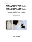
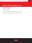
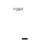
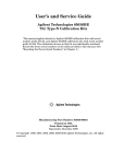
Model 7711/7712
User’s Guide
PA-818 Rev. B / 8-03
A GREATER MEASURE OF CONFIDENCE
Safety Precautions
The following safety precautions should be observed before using
this product and any associated instrumentation. Although some instruments and accessories would normally be used with non-hazardous voltages, there are situations where hazardous conditions
may be present.
This product is intended for use by qualified personnel who recognize shock hazards and are familiar with the safety precautions required to avoid possible injury. Read and follow all installation,
operation, and maintenance information carefully before using the
product. Refer to the manual for complete product specifications.
If the product is used in a manner not specified, the protection provided by the product may be impaired.
The types of product users are:
Responsible body is the individual or group responsible for the use
and maintenance of equipment, for ensuring that the equipment is
operated within its specifications and operating limits, and for ensuring that operators are adequately trained.
Operators use the product for its intended function. They must be
trained in electrical safety procedures and proper use of the instrument. They must be protected from electric shock and contact with
hazardous live circuits.
Maintenance personnel perform routine procedures on the product
to keep it operating properly, for example, setting the line voltage
or replacing consumable materials. Maintenance procedures are described in the manual. The procedures explicitly state if the operator
may perform them. Otherwise, they should be performed only by
service personnel.
Service personnel are trained to work on live circuits, and perform
safe installations and repairs of products. Only properly trained service personnel may perform installation and service procedures.
Keithley products are designed for use with electrical signals that
are rated Measurement Category I and Measurement Category II, as
described in the International Electrotechnical Commission (IEC)
Standard IEC 60664. Most measurement, control, and data I/O signals are Measurement Category I and must not be directly connected to mains voltage or to voltage sources with high transient overvoltages. Measurement Category II connections require protection
for high transient over-voltages often associated with local AC
mains connections. Assume all measurement, control, and data I/O
connections are for connection to Category I sources unless otherwise marked or described in the Manual.
Exercise extreme caution when a shock hazard is present. Lethal
voltage may be present on cable connector jacks or test fixtures. The
American National Standards Institute (ANSI) states that a shock
hazard exists when voltage levels greater than 30V RMS, 42.4V
peak, or 60VDC are present. A good safety practice is to expect
that hazardous voltage is present in any unknown circuit before
measuring.
Operators of this product must be protected from electric shock at
all times. The responsible body must ensure that operators are prevented access and/or insulated from every connection point. In
some cases, connections must be exposed to potential human contact. Product operators in these circumstances must be trained to
protect themselves from the risk of electric shock. If the circuit is
capable of operating at or above 1000 volts, no conductive part of
the circuit may be exposed.
Do not connect switching cards directly to unlimited power circuits.
They are intended to be used with impedance limited sources.
NEVER connect switching cards directly to AC mains. When connecting sources to switching cards, install protective devices to limit fault current and voltage to the card.
Before operating an instrument, make sure the line cord is connected to a properly grounded power receptacle. Inspect the connecting
cables, test leads, and jumpers for possible wear, cracks, or breaks
before each use.
When installing equipment where access to the main power cord is
restricted, such as rack mounting, a separate main input power disconnect device must be provided, in close proximity to the equipment and within easy reach of the operator.
For maximum safety, do not touch the product, test cables, or any
other instruments while power is applied to the circuit under test.
ALWAYS remove power from the entire test system and discharge
any capacitors before: connecting or disconnecting cables or jumpers, installing or removing switching cards, or making internal
changes, such as installing or removing jumpers.
Do not touch any object that could provide a current path to the common side of the circuit under test or power line (earth) ground. Always
make measurements with dry hands while standing on a dry, insulated
surface capable of withstanding the voltage being measured.
The instrument and accessories must be used in accordance with its
specifications and operating instructions or the safety of the equipment may be impaired.
Do not exceed the maximum signal levels of the instruments and accessories, as defined in the specifications and operating information, and as shown on the instrument or test fixture panels, or
switching card.
When fuses are used in a product, replace with same type and rating
for continued protection against fire hazard.
Chassis connections must only be used as shield connections for
measuring circuits, NOT as safety earth ground connections.
If you are using a test fixture, keep the lid closed while power is applied to the device under test. Safe operation requires the use of a
lid interlock.
5/03
If a
screw is present, connect it to safety earth ground using the
wire recommended in the user documentation.
The ! symbol on an instrument indicates that the user should refer to the operating instructions located in the manual.
The
symbol on an instrument shows that it can source or measure 1000 volts or more, including the combined effect of normal
and common mode voltages. Use standard safety precautions to
avoid personal contact with these voltages.
The
frame.
symbol indicates a connection terminal to the equipment
The WARNING heading in a manual explains dangers that might
result in personal injury or death. Always read the associated information very carefully before performing the indicated procedure.
The CAUTION heading in a manual explains hazards that could
damage the instrument. Such damage may invalidate the warranty.
Instrumentation and accessories shall not be connected to humans.
Before performing any maintenance, disconnect the line cord and
all test cables.
To maintain protection from electric shock and fire, replacement
components in mains circuits, including the power transformer, test
leads, and input jacks, must be purchased from Keithley Instruments. Standard fuses, with applicable national safety approvals,
may be used if the rating and type are the same. Other components
that are not safety related may be purchased from other suppliers as
long as they are equivalent to the original component. (Note that selected parts should be purchased only through Keithley Instruments
to maintain accuracy and functionality of the product.) If you are
unsure about the applicability of a replacement component, call a
Keithley Instruments office for information.
To clean an instrument, use a damp cloth or mild, water based
cleaner. Clean the exterior of the instrument only. Do not apply
cleaner directly to the instrument or allow liquids to enter or spill
on the instrument. Products that consist of a circuit board with no
case or chassis (e.g., data acquisition board for installation into a
computer) should never require cleaning if handled according to instructions. If the board becomes contaminated and operation is affected, the board should be returned to the factory for proper
cleaning/servicing.
Keithley Instruments, Inc.
28775 Aurora Road
Cleveland, Ohio 44139
(440) 248-0400
Fax: (440) 248-6168
www.keithley.com
Model 7711/7712
User’s Guide
The information in this User’s Guide is organized as follows:
Introduction on page 2
• Available accessories on page 2
Card configuration — schematic on page 3
Expansion on page 4
• Multiplexer examples on page 4
• 4 × 4 Blocking matrix example on page 7
• 4 × 4 Non-blocking matrix example on page 8
Wiring procedure on page 10
Operation on page 11
• Channel assignments on page 11
Close/Open channels on page 11
• Multiple channel operation on page 11
S-parameters on page 12
• Unlocking calibration on page 12
• CALibration subsystem on page 13
SYSTem subsystem on page 14
Measurement considerations on page 15
• Termination of unused connectors on page 15
• Power handling on page 15
• Additional measurement uncertainty on page 16
Application example on page 18
Service on page 22
• Performance verification on page 22
• Replaceable parts on page 24
PA-818 Rev. B / 8-03
Introduction
If you have any questions after reviewing this information, please contact your local Keithley representative or call one of our
Applications Engineers at 1-800-KEITHLEY (U.S. and Canada only).
The Model 7711/7712 is a single-pole dual 1 × 4 RF Multiplexer module (8 channels, no measurement capability). The 1 × 4
multiplex is a cascading tree design — one of the channels of each bank is always connected to a common out. The 1 × 4
multiplex is also referred to as a single-pole 4-throw (SP4T) switch. Refer to the simplified schematic in Figure 1 or the
specifications. The multiplex switching can be used to connect one instrument to multiple devices (1:N) or multiple
instruments to a single device (N:1). This card expands the Integra Series’ general purpose AC switching capability by
providing an RF switching capability above 1MHz. Each card has the following features:
• 10 SMA connectors with 50Ω impedance
• Frequencies (refer to specifications)
Model 7711 — up to 2 GHz
Model 7712 — up to 3.5 GHz
• Two channels can be closed at one time—one channel to OUT A (channels 1–4) and one to OUT B (channels 5–8)
• Designed specifically for use with the Integra Series including Keithley’s Models 2700, 2701 and 2750 Multimeter
/ Data Acquisition Systems
NOTE
All references to the Model 27xx apply to the Models 2700, 2701, and 2750.
With this in mind, the capability of the Model 27xx is expanded for applications such as the following:
• General AC and digital signal routing to and from test equipment. This includes oscilloscopes, function generators,
pulse generators, counter/timers, and signal analysis tools including network and jitter analyzers. Also, this includes
diverse applications that require RF and digital routing plus DC measurements for research, development, burn-in
and production testing, AC ripple and noise test for switching power supplies, and DC-DC converters.
• Research, development, and burn-in of temperature compensated oscillators.
• Research, development, and production test of communications or networking products including Ethernet, DSL,
DS3, T1/E1, etc.
WARNING
Before operating the Model 27xx with an accessory card, verify that the card is properly
installed and the mounting screws are tightly fastened. If the mounting screws are not
properly connected, an electrical shock hazard may be present.
Available accessories
Model 7711 only
7711-BNC-SMA
7051-2
7051-5
7051-10
2
Male SMA to Female BNC, five 0.15m (0.5ft) cables
(Insertion loss < 1dB@1GHz, VSWR < 1.5@ 1GHz)
BNC cable, male to male, 0.6m (2ft.)
BNC cable, male to male, 1.5m (5ft.)
BNC cable, male to male, 3.0m (10ft.)
Model 7711/7712
7712-SMA-1
SMA cable, male to male, flexible, low loss, 1m (3.3ft)
(Insertion loss < 0.65dB @ 2GHz, VSWR < 1.11 @2GHz)
Female SMA to Male N-Type Adapter
SMA cable, male to male, 0.3m (1ft)
SMA cable, male to male, 0.15m (0.5ft)
7712-SMA-N
S46-SMA-1
S46-SMA-0.5
Card configuration—schematic
Figure 1 shows a simplified schematic diagram of the Model 7711/7712 module. As shown, the Model 7711/7712 has channels
that are grouped into dual 1 × 4 multiplexers. The multiplexer’s design allows 1 channel of each set of 4 to be closed at a time
(1 of 4 tree structure). Also, channels 1 and 5 are normally closed to OUT A and OUT B, respectively.
NOTE
The Model 7711/7712 relays are set to close channels 1 and 5 a few seconds after either a power
cycle or a *RST command is issued (see Figure 1 for a schematic).
Figure 1
Simplified schematic for Model 7711/7712
Ch1
Ch2
OUT A
Ch3
Ch4
Ch5
Ch6
OUT B
Ch7
Ch8
NOTE
To close channels 1 and 5 on a Model 7711/7712 in slot 1, send: :ROUT:MULT:CLOS
(@101,105)
The channels are controlled over the bus or from the front panel. The grounds for these channels are non-isolated. Detailed
connection information is contained later in this guide. By using the ROUT:MULT commands (refer to Section 2 of the
Model 27xx User’s Manual), they can be manually configured.
3
Expansion
One Model 7711/7712 configuration is a dual (2 bank) 1 × 4 multiplexer. A single Model 7711/7712 module can also be
configured as a 4 × 4 blocking matrix. The 7711/7712 can be combined with additional modules to further expand its
multiplexing and matrix switching capabilities (specifications may degrade when the Model 7711/7712 is used in multiple
module configurations). Refer to Table 1 for possible expansion information. Examples of multiplexer and blocking matrix
expansion follow Table 1.
Table 1
Matrix and multiplex expansion
Multiplexer
Number of 7711/7712 Cards
1×4
1×8
1 × 12
1
X
2
X
X
X
3
X
X
X
Blocking Matrix
1 × 16
4×4
4×8
4 × 12
4 × 16
X
X
X
X
X*
X
X
X
*Using four cards in a Model 2750, a 4 × 4 non-blocking matrix can be created (see the 4 × 4 non-blocking matrix example on page 9).
NOTE
The commands in this section are formatted as follows: Command (@Model 27xx Slot #,
Channel #)
Multiplexer examples
NOTE
To minimize noise within the system, terminate unused channels with 50Ω loads. If 50Ω loads are
not available, terminating unused connectors with a cable may also reduce noise within the
system.
Figure 2 shows how to create a 1 × 8 SP8T MUX (single-pole eight-throw multiplex) using two Model 7711 cards. Channels 1
and 2 are connected to OUT A and OUT B of the second card in slot two. Terminate unused channels (in the example, channels
3 and 4 on the Model 7712 in slot one) with a 50Ω load.
Figure 3 shows how to create a 1 × 12 MUX using two Model 7711 cards.
4
NOTE
Channels 3 and 4 (of 7711 in slot 1) may also be connected to other banks that will create a 1 × 12
multiplexer (or a 1 × 16 multiplexer). See Figure 4 for a 1 × 12 example. The following is a list of
sample commands needed to operate the 1 × 8 multiplexer.
NOTE
The command “ROUTe:MULTiple:CLOSe (@<channel list>)” closes one channel per bank (two
banks per Model 7711/7712 module), and opens all other channels within the same bank.
Figure 2
1 x 8 MUX expansion
7711
SLOT 1
CH8
CH7
OUT B
CH6
CH5
CH4
CH3
OUT A
CH2
CH1
CH4
CH3
OUT A
CH2
CH1
7711
SLOT 2
CH8
CH7
OUT B
CH6
CH5
NOTE: The simplified schematic is shown in the
power up state (Channels 1 and 5 are
closed for cards in slots 1 and 2).
Grayed channels are not used in this
1 × 8 SP8T MUX.
S46-SMA-0.5
Cable (Qty 2)
7711/7712
Slot 1
7711/7712
Slot 2
Ch1
OUT A
>>
Ch2
Ch3
Ch1
OUT A
>>
Ch4
Ch7
Ch8
Ch3
Ch4
Ch5
Ch6
Ch2
Ch5
OUT B
>>
Ch6
Ch7
Ch8
To close to this crosspoint (CH7) send:
ROUTe:MULTiple:CLOSe(@102,207)
5
Figure 3
1 × 12 MUX expansion
7711
SLOT 1
CH8
CH7
OUT B
CH6
CH5
CH4
CH3
OUT A
CH2
CH1
CH4
CH3
OUT A
CH2
CH1
7711
SLOT 2
CH8
CH7
OUT B
CH6
CH5
NOTE: The simplified schematic is shown in the
power up state (Channels 1 and 5 are
closed for cards in slots 1 and 2).
Grayed channels are not used in this
1 × 12 SP12T MUX.
S46-SMA-0.5
Cable (Qty 3)
7711/7712
Slot 1
7711/7712
Slot 2
Ch1
OUT A
>>
Ch2
Ch3
To close to this crosspoint (CH3) send:
ROUTe:MULTiple:CLOSe(@101,203)
Ch1
OUT A
>>
Ch4
Ch2
Ch3
Ch4
To close to this crosspoint (CH7) send:
ROUTe:MULTiple:CLOSe(@102,207)
Ch5
OUT B
>>
Ch6
Ch7
Ch8
Ch5 (Ch9)
Terminate this
unused channel
in bank 1 with a 50Ω
load or an unconnected
S46-SMA-0.5 cable.
OUT B
>>
NOTE: Channels 5-8 on the 7711/7712
in slot 1 correspond to crosspoints
Channels 9-12 of the 1 × 12 SP12T
MUX.
6
Ch6 (Ch10)
Ch7 (Ch11)
Ch8 (Ch12)
To close to this crosspoint (CH11) send:
ROUTe:MULTiple:CLOSe(@103,107)
4 × 4 Blocking matrix example
Figure 4 shows how to connect a single Model 7711 in a 4 × 4 blocking matrix. This configuration provides a convenient way
to connect four DUTs to four different test instruments. In this configuration, one channel of bank 1 (channels 1 – 4) may be
routed to any channel of bank 2 (channels 5 – 6). Use a short coaxial cable to connect OUT A to OUT B (S46-SMA-0.5). contains example commands.
Figure 4
4 × 4 blocking matrix expansion
7711
CH8
CH7
OUT B
CH6
CH5
CH4
CH3
OUT A
CH2
CH1
S46-SMA-0.5
Cable (Qty 1)
7711/7712
Slot 1
Ch1
Ch5
Ch2
Ch6
Ch3
OUT A
OUT B
Ch4
Ch7
Ch8
To route the signal between Ch4 and Ch8 send:
ROUTe:MULTiple:CLOSe(@104,108)
NOTE: The simplified schematic is shown in the
power up state (Channels 1 and 5
closed).
Table 2
4 × 4 Blocking matrix commands
Command
Signal path
ROUTe:MULTiple:CLOSe (@101,105)
Routes signal through channels 1 and 5
ROUTe:MULTiple:CLOSe (@103,106)
Routes signal through channels 3 and 6
7
4 x 4 Non-blocking matrix example
Using a Model 2750 and four Model 7711/7712 cards, a 4 × 4 non-blocking matrix can be created. Figure 5 shows how to
connect the 7711/7712 modules. This configuration provides a convenient way to simultaneously connect up to 4 DUTs to 4
different test instruments. Use a short coaxial cable to connect the OUTs of each module as shown. contains a couple of
sample commands to control the matrix.
To use , select the IN connection (IN 1 – IN 4), and then in the same square select the OUT connection (OUT1 - OUT4). Send
the ROUTe:MULTiple:CLOSe command with the channels in both “Ch” columns.
Table 3
4 × 4 Sample non-blocking matrix commands
Command
Signal path
ROUTe:MULTiple:CLOSe (@101,405)
Routes signal from IN1(OUT A of slot 1) through
OUT4 (OUT B of slot 4).
ROUTe:MULTiple:CLOSe (@101,405,108,302)
Routes signal from IN1 (OUT A of slot 1) through
OUT4 (OUT B of slot 4), and also from IN2 (OUT B
of slot 1) through OUT1 (OUT A of slot 4).
Table 4
4 × 4 Non-blocking matrix channels
8
IN
Ch
Ch
OUT
IN
Ch
Ch
OUT
IN 1
101
405
OUT4
IN 3
201
407
OUT4
102
401
OUT3
202
403
OUT3
103
305
OUT2
203
307
OUT2
104
301
OUT1
204
303
OUT1
IN
Ch
Ch
OUT
IN
Ch
Ch
OUT
IN 2
105
406
OUT4
IN 4
205
408
OUT4
106
402
OUT3
206
404
OUT3
107
306
OUT2
207
308
OUT2
108
302
OUT1
208
304
OUT1
Figure 5
4 x 4 Non-blocking matrix expansion
7711
CH8
CH7
OUT B
CH6
CH5
CH4
CH3
OUT A
CH2
CH1
SLOT 3
SLOT 4
7711
7711
CH8
CH7
OUT B
CH6
CH5
CH4
CH3
OUT A
CH2
CH8
CH1
CH7
OUT B
CH6
CH5
CH4
CH3
OUT A
CH2
CH1
SLOT 1
SLOT 2
7711
CH8
CH7
OUT B
CH6
CH5
CH4
CH3
IN1
OUT A
CH2
CH1
IN2
OUT A
IN3
OUT B
OUT A
OUT B
SLOT 1
Channel 1
2
3
4
5
NOTE: The simplified schematic
is shown in the power
up state (Channels 1
and 5 closed for cards
in all slots).
IN4
SLOT 2
6
7
8
1
2
3
4
5
6
7
8
Channel
OUT A
1
2
OUT1
3
OUT B
5
SLOT 3
4
6
OUT2
7
8
OUT A
1
2
OUT3
3
6
OUT B
5
SLOT 4
4
OUT4
7
8
9
Wiring procedure
WARNING
Do not exceed the maximum specifications for the Model 7711/7712 module. Refer to
Appendix A for specifications.
The default closed channels are 1 and 5 — the lowest number in each bank. At power-up, the lowest numbered channel in each
bank will always be closed. If using a saved setup that calls for another channel to be closed, the card will be switched to that
channel but only after the firmware has finished "waking up." Therefore, the lowest channel will ALWAYS be closed for at
least a brief time at power-up. The user needs to verify that nothing is connected to the lowest channel in each bank that could
be damaged.
The connectors on the card are standard SMA type connectors. When making or breaking connections, use a torque wrench to
produce mating torque of 0.9 N•m (8in•lbs).
NOTE
Use a box-spanner torque wrench similar to Suhner Type 74 Z-1-0-21, Identification number
543130. This wrench is for SMA connectors with a 1.00 N•m torque with 8.0mm (0.315 in.) across
the flats.
Figure 6
Model 7711/7712 channel connections
7711
CH8
WARNING
CH7
OUT B
CH6
CH5
CH4
CH3
OUT A
CH2
CH1
Do not touch live RF (radio frequency) conductors, even at low voltages! RF behaves
differently than DC or low frequency AC. Low voltage RF can cause severe burns. RF
signals spread out over body areas generating substantial currents at the points of
contact with RF conductors.
Make all connections using correct wire size. If BNC connections are required, use the SMA to BNC adapter cables (see
Available accessories on page 2).
Specifications
Full Model 7711/7712 specifications are included at the end of this User Guide.
10
Operation
NOTE
The Model 7711/7712 modules cannot be included in scanlists.
Detailed information to close and open switching module channels is provided in Section 2 of the Model 27xx User’s Manual.
The following summarizes basic operation and provides operating information specific to the Model 7711/7712.
Channel assignments
NOTE
Measurement functions cannot be assigned to Model 7711/7712 modules. For example, if a
Model 7711/7712 is installed in slot 1 and the SENSE:FUNC ‘VOLT:AC’, (@101) command is
sent, a -221, “Settings Conflict” error would be reported.
The Model 2700/2701 has two slots for switching modules, and the Model 2750 has five slots. To control the appropriate
switching module, the slot number must be included with the switching module channel number when you specify a channel.
The channel assignment is formatted as follows:
SCH
where: S is the slot number
CH is the channel number
Examples:
101 = Slot 1, Channel 1
210 = Slot 2, Channel 10
506 = Slot 5, Channel 6 (Model 2750)
NOTE
For remote operation, the 3-digit channel assignment is included in the channel list parameter for
the commands.
Close/Open channels
Multiple channel operation
WARNING
Multiple channel operation should only be performed by experienced test engineers who
recognize the dangers associated with multiple channel closures.
For the Model 7711/7712, multiple channel operation provides control of one or two Model 7711/7712 modules in a
Model 2700/2701 (or up to 5 in a Model 2750). OUT A automatically switches as appropriate for channels 1 – 4, and OUT B
automatically switches as appropriate for channels 5 – 8 for each module. When you close two channels in a single module
(one for OUT A and one for OUT B), the appropriate channels will close channels outside of the banks (or on other modules)
are not affected by channel closures.
The following paragraphs summarize multiple channel operation for the front panel and from the remote interface (bus).
Front panel
• For the Models 2700/2701 and 2750, the MULTI option of the CLOSE key can be used to close a channel.
• For the Models 2700/2701 and 2750, the ALL option of the OPEN key closes channels 1 and 5 to OUT A and OUT
B respectively.
11
Remote interface
ROUT:MULT:CLOS <clist> — Closes specified channels (unlisted channels not affected unless in the same bank).
ROUT:MULT:CLOS? — Returns list of all closed channels.
ROUT:MULT:CLOS:STAT? <clist> — Query closed channels in list (1 = closed).
ROUT:OPEN:ALL — Closes channels 1 and 5 to OUT A and OUT B respectively
The following command is not available:
ROUT:MULT:OPEN <clist> — Invalid command for the Model 7711/7712 module.
NOTE
For example, if a Model 7711/7712 is installed in slot 1 and the ROUT:MULT:OPEN (@101) command is sent, a -221, “Settings Conflict” error would be reported.
DMM measurements
None of the channels of the 7711/7712 module are connected to the internal DMM (the channels cannot be connected to the
backplane). If your test system requires DMM measurements, you can use a measure card in one of the other mainframe slots
or you can use the front panel inputs of the Model 27xx.
Remember to use multiple channel operation to control the 7711/7712 module and system channel operation to control a
measure card for DMM measurements. If you attempt to close a 7711/7712 module channel using front panel system channel
operation, the message “NO MEAS CARD” will be displayed briefly.
If you use front panel inputs for measurements, make sure that the front panel INPUT switch is in the out (F) position.
S-parameters
S-parameters allow a text string of up to 238 ASCII characters to be stored on a module. This can be used for system
calibration of cable and module losses. The calibration text string is stored on the module, independent of the Model 27xx
mainframe.
Unlocking calibration
Use the following sequence of commands to unlock calibration (factory default code):
CAL:PROT:CODE “KI0027xx”
CAL:PROT:CARD1:INIT
CAL:PROT:CARD1:SPAR “......”
CAL:PROT:CARD1:SAVE
where: xx = 00 (for 2700)
xx = 01 (for 2701)
xx = 50 (for 2750)
NOTE
12
Your mainframe calibration unlock code will remain the factory default code unless it is changed.
CALibration subsystem
Commands to perform output operations are listed in Table 5. Details on these commands follow the table.
NOTE
The following commands for the CALibration subsystem are specific to the Model 7711/7712
module. It is only available if a Model 7711/7712 is installed.
Table 5
CALibration subsystem commands
Command
Description
2700/2701 Commands
CALibration
:PROTected
:CARD1
:INITiate
:SPARameters <string>
:SPARameters?
:CARD2
:SPARameters?
2750 Commands (only)
CALibration
:CARD1
:INITiate
:SPARameters <string>
:CARD
:SPARameters? <NRf>
Default
Path to CARD1 commands.
Initiate command—required before sending s-parameters.
Enter up to 238 characters for storage of S-parameter information about
the card in slot 1.
Query the ASCII information for CARD1.
Path to CARD2 commands.
Query the ASCII information for CARD2.
Path to CARD commands.
Initiate command—required before sending s-parameters.
Enter up to 238 characters for storage of S-parameter information about
the card in slot 1.
Path to s-parameter queries.
Query the ASCII information for card in slot <NRf>.
Empty
Empty
:SPARameters <string>
If the card in this slot is not a valid RF card (Model 7711, etc.), then a -221, “Settings Conflict” error is returned. Any valid
ASCII information can be stored in the string space; it is not error checked in any way.
NOTE
S-parameter data can only be written to a card in slot 1. The S-parameters are treated like
card-cal constants, meaning that you must send a CAL:PROT:CARD1:INIT command before
sending the SPARameters, and they are only saved on the card after a CAL:PROT:CARD1:SAVE
command. The S-parameter can be read from any slot.
:SPARameters? <NRf>
Query S-parameter
S-parameter data can only be written to a card in slot 1. This is consistent with other Integra series type card calibrations that
are allowed in slot 1 only. Also, the Model 2750 can be queried using CAL:PROT:CARD1:SPAR
NOTE
Errors +518 and +519 are provided to flag corrupted S-parameter information or flag
S-parameter information that was not properly initialized.
13
SYSTem subsystem
Commands to perform system operations are listed in Table 6. Details on these commands follow the table.
NOTE
The following commands for the Model 7711/7712 SYSTem subsystem are included here for
reference.
Table 6
SYSTem subsystem commands
Command
2700/2701 Commands
:SYSTem
:CARD1
:CARD2
:SNUMber?
:SWRevision?
:VMAX?
:MUX?
:SNOpen?
:BANKs?
2750 Commands (only)
:CARD
:SNUMber? <NRf>
:SWRevision? <NRf>
:VMAX? <NRf>
:MUX? <NRf>
:SNOpen? <NRf>
:BANKs? <NRf>
:CARD1
:CARD2
Description
Default
Path to queries for slot 1 card.
Path to queries for slot 2 card.
Request serial number of card in Slot x.
Request firmware revision of card in Slot x.
Query the highest allowed voltage on this card.
Return TRUE if this card support ANY mux channels.
Query whether the card is of the "single, no-open" type.
This query returns the number of banks on the card. If the card is not of the
Single, No-Open type, then a -221 "Settings Conflict" error results with
this query.
Path to queries (slot is designated by <NRf> after query command).
Request serial number of card in Slot x.
Request firmware revision of card in Slot x.
Query the highest allowed voltage on this card.
Return TRUE if this card support ANY mux channels.
Query whether the card is of the "single, no-open" type.
This query returns the number of banks on the card. If the card is not of the
Single, No-Open type, then a -221 "Settings Conflict" error results with
this query.
Model 2700/2701 commands
If no card is in slot 1, then all commands in Table 6 generate a -241 “hardware missing” error. If the card does not support the
feature or channels being queried, then 0 will be returned.
:MUX?
Returns either a 1 or 0. (For a Model 7711/7712 card, a 0 is returned.)
:SNOpen?
"single, no-open" type — The card is organized into banks of channels, and one channel must always be closed within that
bank. The Model 7711 is representative of this class with two banks of 4 channels each. Returns either a 1 or 0.
(For a 7711/7712 card, a 1 is returned.)
14
:CARD
Model 2750 commands only
If no card is in slot <NRf>, then all of these commands will generate a -241 “hardware missing” error. If the card does not
support the feature or channels being queried, then 0 will be returned.
Unlike the Model 2700/2702, the Model 2750 SYST:CARD queries have the slot passed as a <NRf> following the query
(rather than incorporated into the command name). For compatibility with existing Model 2700/2702 software, the
Model 2750 also accepts SYST:CARD1 or SYST:CARD2 (not recommended for queries when developing new software).
Example: To query the maximum voltage allowed on the card in slot 3, send:
:SYST:CARD:VMAX? 3
Measurement considerations
Termination of unused connectors
To minimize noise within the system, terminate unused channels with 50Ω loads. If 50Ω loads are not available, terminating
unused connectors with a cable may also reduce noise within the system.
Power handling
The graph in Figure 7 shows the maximum amount of power per channel that can be routed using the Model 7711 or
Model 7712 while maintaining proper digital multimeter accuracy. Power levels of up to 10 watts at frequencies > 200MHz
can be used, but this may cause measurement errors. For example, routing 10 watts of power at 1GHz may cause the
Model 2700/2702 to have an additional 6µV offset uncertainty when measuring DC voltages. For the Model 2750, the
precision low level circuitry may cause uncertainty of 30µV. Moving the Model 7711/7712 to a higher number slot will reduce
this uncertainty.
Figure 7
Carry power (per channel) vs. frequency
12
200MHz
10
Power (watts)
8
Additional DMM Uncertainty
6
4
500MHz
2
0
10
100
1000
3500
MHz
15
Additional measurement uncertainty
Table 7 lists additional uncertainty to the published specifications for the Model 7708. Other modules, such as the Model 7700
(which measures thermocouple temperature), are also affected by this heat but are still within published specification. The
amount of uncertainty is dependent on:
• Model 7711/7712 slot location
• The amount of time the channel is programmed as an output
• Which other model 77XX module(s) are being used
The listed uncertainty in Table 7 is listed for channels 4 and 8 closed. The uncertainty is linear—for each channel programmed
as input or off, there will be approximately 25 percent reduction in the listed on uncertainty. Table 8 lists the percentage of
additional uncertainty for specific channel pairs closed.
Table 7
Additional uncertainty for Model 7711/7712
Thermocouple
Range
7708
J
-200 to 0˚C
0 to +768˚C
K
-200 to 0˚C
0 to +1372˚C
0.4
N
-200 to 0˚C
0 to +1300˚C
0.75
0.15
T
-200 to 0˚C
0 to +400˚C
0.4
E
-200 to 0˚C
0 to +1000˚C
0.15
R
0 to +400˚C
0 to +1768˚C
1.5
S
0 to +400˚C
0 to +1768˚C
1.5
B
350 to 1100˚C
0 to +1820˚C
2.4
0.6
Notes:
1. The above listed uncertainties are guaranteed by design for thermocouple types J, K, N,
T, E, R, S, B.
2. When the Model 7711/7712 and Model 7708 are used together, the Model 7711/7712
must be installed in the lowest numbered slot.
For example: Model 2700/2701: 7711/7712 in slot 1, 7708 in slot 2
Model 2750:
7711/7112 in slot 2, 7708 in slot 3
16
Table 8
Percent of additional uncertainty
Channels closed
Percent of additional
uncertainty (from Table 7)
4 and 8
2 and 8
3 and 8
4 and 6
4 and 7
1 and 8
2 and 6
2 and 7
3 and 6
3 and 7
4 and 5
1 and 6
1 and 7
2 and 5
2 and 6
1 and 5
100%
75%
75%
75%
75%
50%
50%
50%
50%
50%
50%
25%
25%
25%
25%
0%
17
Application example
The following application example is for power supply testing. For basic overview and switching, refer to Figure 8. For the
tests performed, refer to the provided code (Figure 9). Basic knowledge for Visual Basic functions, such as the CStr() function,
as well as how forms work in Visual Basic, is required to fully understand the example.
Figure 8
Simplified connection schematic (one power supply shown)
Oscilloscope
OUT A
Ch1
7711-SMA-BNC
Cable
7712-SMA-1
Cable
7711
Thermocouple
Power Supply
Input
Output
High Line
132V
~
LO
HI
Ch1 LO DCV
Low Line
108V
~
HI
ACV HI Ch2
LO
10%
Load
90%
Load
HI
Ch3 LO CONT
7705
Ch1
7705
Ch11
TEMP HI Ch4
LO
7705
Ch21
7705
Ch31
7700
Figure 9
Visual basic application example—power supply testing
''
''
''
''
''
''
''
''
''
''
''
''
''
''
''
''
''
''
''
''
''
''
''
--------------------------------------------------------------------------------------------------------------------7711 Application Example
--------------------------------------------------------------------------------------------------------------------This program tests a set of power supplies using a 2750 loaded with a 7700,
7711, and a 7705.
The following occurs:
1)
The 7700 takes DCV, ACV, 2W OHMS (CONT), and TEMP measurements.
2)
Limits are used in each of the measurements by the 7700.
A) DCV limits are set to 10% of the power supply's output.
B) ACV limits are 108 and 132V.
C) 2W OHMS limits are -0.01 and 2 ohms.
D) TEMP limits are 70 and 125 C.
3)
RF switching to an oscilloscope is obtained using a 7711 where the AC ripple
is measured.
4)
A 7705 is used to switch loads and to control the line input voltage
to the DUTs (power supplies).
Please note:
The maximum number of power supplies that can be used with this example is 4.
---------------------------------------------------------------------------------------------------------------------
18
Option Explicit
'' --------------------------------------------------------------------------------------------------------------------'' Constants
'' --------------------------------------------------------------------------------------------------------------------Const MAXLEN = 6400
' Constant used with ENTER function.
Const LENGTH = 6400
' Constant used with ENTER function.
Const ENTER_TIMEOUT = 3000
' Length of time the ENTER function will
' wait for a query.
Const ADDRESS = 16
' DMM setup address.
'' Slot assignments.
Const SLOT_7700 = 1
Const SLOT_7711 = 2
Const SLOT_7705 = 3
'' Number of configurations, power supply units, and functions.
Const NUMBER_OF_DUTS = 4
Const NUMBER_OF_FUNCTIONS = 4
' DCV, ACV, CONT, and TEMP.
Const NUMBER_OF_SUPPLY_CONFIGURATIONS = 4
' Includes HIGH/ LOW line and 10%/90% load.
Const N_READINGS = NUMBER_OF_DUTS * NUMBER_OF_FUNCTIONS * NUMBER_OF_SUPPLY_CONFIGURATIONS
'' Constants to define limits for the different measurements.
Const POWER_SUPPLY_VOLTAGE = 5
' Voltage output of power supplies.
Const DCV_MAX = POWER_SUPPLY_VOLTAGE * 1.1
' Allow power supply to vary by 10%.
Const DCV_MIN = POWER_SUPPLY_VOLTAGE * 0.9
Const ACV_MAX = 132
' ACV input voltage to power supply limits.
Const ACV_MIN = 108
Const CONT_MAX = 2
' Limit failure will occur at 2 ohms or more.
Const CONT_MIN = -0.01
Const TEMP_MAX = 125
' Max. and min. limits for temperature.
Const TEMP_MIN = 70
'' Constants to define power supply configurations.
Const HIGH_LINE = 1
Const LOW_LINE = 2
Const TEN_PERCENT_LOAD = 1
Const NINETY_PERCENT_LOAD = 2
' Global variables.
Dim Status As Integer
Dim Readings(N_READINGS) As String
Dim Reading_Counter As Integer
' Variable used by the send() function.
' Array to store readings.
' Index to Readings().
'' --------------------------------------------------------------------------------------------------------------------'' 7700 Channel Configurations
'' --------------------------------------------------------------------------------------------------------------------'' Configure_Limits(,,) ''
Sets the limits for a given channel given by the constants defined above.
''
'' Configure_7700_DCV(,) ''
Sets a channel to measure DCV.
''
'' Configure_7700_ACV() ''
Configures a channel to measure ACV.
''
'' Cofigure_CONT() ''
Configures the channel to measure 2W ohms.
''
This measurement is used instead of CONT, so we can select the ohm's limits.
''
'' Configure_7700_TEMP() ''
Sets a channel to measure temperature using *RST default.
''
'' Configure_Channel() ''
Uses the above functions to do the following on the 7700:
''
1. Sets channels 1,5,9, and 13 to DCV.
''
2. Sets channels 2,6,10, and 14 to ACV.
''
3. Sets channels 3,7,11, and 15 to CONT.
''
4. Sets channels 4,8,12, and 16 to TEMP.
''
5. Places the box into Auto-Configuration Mode.
''
''
Note:
Auto-configuration mode brings in the individual channels'
''
settings when that channel is closed.
'' --------------------------------------------------------------------------------------------------------------------Private Sub Configure_7700_Limits(Channel_Num As Integer, Ulimit As Integer, Llimit As Integer)
Dim Channel_Str As String
Dim Upper_Limit As String
Dim Lower_Limit As String
Channel_Str = ",(@" & CStr(Channel_Num) & ")"
Upper_Limit = CStr(Ulimit)
Lower_Limit = CStr(Llimit)
' Converts a number to an ASCII channel parameter.
Call send(ADDRESS, "CALC3:LIM1:STAT ON" & Channel_Str, Status)
Call send(ADDRESS, "CALC3:LIM1:UPP:DATA " & Upper_Limit & Channel_Str, Status)
Call send(ADDRESS, "CALC3:LIM1:LOW:DATA " & Lower_Limit & Channel_Str, Status)
End Sub
' Enable Limit1 for DCV.
' Set upper limit.
' Set lower limit.
Private Sub Configure_7700_DCV(Channel_Num As Integer, Power_Supply_DCV As Integer)
Dim Channel_Str As String
Channel_Str = ",(@" & CStr(Channel_Num) & ")"
Call send(ADDRESS, "SENS:FUNC 'VOLT:DC'" & Channel_Str, Status)
Call send(ADDRESS, "SENS:VOLT:DC:RANG 100" & Channel_Str, Status)
' Set channel to measure DCV.
' Set voltage range(Power Supply is at 5V).
Call Configure_7700_Limits(Channel_Num, DCV_MAX, DCV_MIN)
End Sub
Private Sub Configure_7700_ACV(Channel_Num As Integer)
Dim Channel_Str As String
Channel_Str = ",(@" & CStr(Channel_Num) & ")"
Call send(ADDRESS, "SENS:FUNC 'VOLT:AC'" & Channel_Str, Status)
Call send(ADDRESS, "SENS:VOLT:AC:RANG 150" & Channel_Str, Status)
Call Configure_7700_Limits(Channel_Num, ACV_MAX, ACV_MIN)
End Sub
' Set channel to measure ACV.
' Set voltage range.
19
Private Sub Configure_7700_CONT(Channel_Num As Integer)
Dim Channel_Str As String
Channel_Str = ",(@" & CStr(Channel_Num) & ")"
Call send(ADDRESS, "SENS:FUNC 'RES'" & Channel_Str, Status)
Call send(ADDRESS, "SENS:RES:RANG 10" & Channel_Str, Status)
Call send(ADDRESS, "SENS:RES:NPLC 0.1" & Channel_Str, Status)
' Set channel to measure 2W ohms.
' Set resistance range.
' Set meaurement speed to fast.
Call Configure_7700_Limits(Channel_Num, CONT_MAX, CONT_MIN)
End Sub
Private Sub Configure_7700_TEMP(Channel_Num As Integer)
Dim Channel_Str As String
Channel_Str = ",(@" & CStr(Channel_Num) & ")"
Call send(ADDRESS, "SENS:FUNC 'TEMP'" & Channel_Str, Status)
Call send(ADDRESS, "SENS:TEMP:TRAN TC" & Channel_Str, Status)
Call send(ADDRESS, "SENS:TEMP:TC:TYPE T" & Channel_Str, Status)
Call send(ADDRESS, "SENS:TEMP:TC:RJUN:RSEL INT" & Channel_Str, Status)
'
'
'
'
Set channel to TEMP measurement.
Select thermocouple measurement.
Use T thermocouples.
Use internal reference junction.
Call Configure_7700_Limits(Channel_Num, TEMP_MAX, TEMP_MIN)
End Sub
Private Sub Configure_7700_Channels()
Dim I As Integer
Dim POWER_SUPPLY_VOLTAGE As Integer
For I = 0 To NUMBER_OF_DUTS - 1
Call Configure_7700_DCV(1 + (I * NUMBER_OF_DUTS) + (SLOT_7700 * 100), POWER_SUPPLY_VOLTAGE)
Call Configure_7700_ACV(2 + (I * NUMBER_OF_DUTS) + (SLOT_7700 * 100))
Call Configure_7700_CONT(3 + (I * NUMBER_OF_DUTS) + (SLOT_7700 * 100))
Call Configure_7700_TEMP(4 + (I * NUMBER_OF_DUTS) + (SLOT_7700 * 100))
Next
Call send(ADDRESS, "ROUT:CLOS:ACON ON", Status)
' Place instrument in auto-configure mode.
End Sub
'' --------------------------------------------------------------------------------------------------------------------'' 7705 Configurations
'' --------------------------------------------------------------------------------------------------------------------'' Configure_Power_Supplies(,) ''
Uses the 7705 switch card to change the input voltage to the power supplies.
''
They may run at either high line or low line. A load of 10% or 90% is also
''
selected in this function.
''
''
Assume the following for the 7705:
''
1) Channels 1 to 4 connect each of the possible DUTS to HIGH LINE.
''
2) Channels 11 to 14 connect each of the possible DUTS to LOW LINE.
''
3) Channels 21 to 24 connect each of the possible DUTS to 10% load.
''
4) Channels 31 to 34 connect each of the possible DUTS to 90% load.
'' --------------------------------------------------------------------------------------------------------------------Private Sub Configure_Power_Supplies(Line As Integer, Load As Integer)
Dim Min_Channel, Max_Channel As String
' Insert code here to turn off power supply outputs.
Min_Channel = CStr((SLOT_7705 * 100) + 1)
Max_Channel = CStr((SLOT_7705 * 100) + 40)
Call send(ADDRESS, "ROUT:MULT:OPEN (@" & Min_Channel & ":" & Max_Channel & ")", Status)
' Open all 7705 channels.
Select Case (Line)
Case HIGH_LINE
Min_Channel = CStr((SLOT_7705 * 100) + 1)
Max_Channel = CStr((SLOT_7705 * 100) + NUMBER_OF_DUTS)
Call send(ADDRESS, "ROUT:MULT:CLOS (@" & Min_Channel & ":" & Max_Channel & ")", Status)
Case LOW_LINE
Min_Channel = CStr((SLOT_7705 * 100) + 1 + 10)
Max_Channel = CStr((SLOT_7705 * 100) + NUMBER_OF_DUTS + 10)
Call send(ADDRESS, "ROUT:MULT:CLOS (@" & Min_Channel & ":" & Max_Channel & ")", Status)
End Select
Select Case (Load)
Case TEN_PERCENT_LOAD
Min_Channel = CStr((SLOT_7705 * 100) + 1 + 20)
Max_Channel = CStr((SLOT_7705 * 100) + NUMBER_OF_DUTS + 20)
Call send(ADDRESS, "ROUT:MULT:CLOS (@" & Min_Channel & ":" & Max_Channel & ")", Status)
Case NINETY_PERCENT_LOAD
Min_Channel = CStr((SLOT_7705 * 100) + 1 + 30)
Max_Channel = CStr((SLOT_7705 * 100) + NUMBER_OF_DUTS + 30)
Call send(ADDRESS, "ROUT:MULT:CLOS (@" & Min_Channel & ":" & Max_Channel & ")", Status)
End Select
' Insert code here to configure and/ or turn on power supply outputs.
End Sub
''
''
''
''
''
''
--------------------------------------------------------------------------------------------------------------------Measurement Functions
--------------------------------------------------------------------------------------------------------------------Take_Measurements() Closes the appropriate channels and takes a measurement using READ? command.
---------------------------------------------------------------------------------------------------------------------
20
Private
Dim
Dim
Dim
Dim
Sub Take_Measurements()
I, J As Integer
Channel_Num As Integer
Channel_Str As String
Reading As String
For I = 1 To NUMBER_OF_DUTS
Channel_Num = (SLOT_7711 * 100) + I
Channel_Str = "(@" & CStr(Channel_Num) & ")"
Call send(ADDRESS, "ROUT:MULT:CLOS " & Channel_Str, Status)
'
'
'
'
Loop to take measurements for all DUTs.
Determine channel number.
Convert channel to ASCII string parameter.
Route channel on 7711 to Out A.
For J = 1 To NUMBER_OF_FUNCTIONS
' Loop for each measurement function.
Channel_Num = (SLOT_7700 * 100) + J + ((I - 1) * NUMBER_OF_DUTS)
Channel_Str = "(@" & CStr(Channel_Num) & ")"
Call send(ADDRESS, "ROUT:CLOS " & Channel_Str, Status)
' Close measurement channel on the 7700.
Call send(ADDRESS, "READ?", Status)
' Take measurement.
Call enter(Reading, MAXLEN, LENGTH, ADDRESS, Status)
Readings(Reading_Counter) = Reading
Reading_Counter = Reading_Counter + 1
' Store reading.
Next
' Insert code here to take oscilloscope measurements.
Next
End Sub
'' --------------------------------------------------------------------------------------------------------------------'' Main Function
'' --------------------------------------------------------------------------------------------------------------------Private Sub Start_Click()
Reading_Counter = 0
' Reset index counter.
Call settimeout(ENTER_TIMEOUT)
' Set timeout valuefor enter function.
Call initialize(21, 0)
' Initialize GPIB.
Call send(ADDRESS, "*RST", Status)
Call send(ADDRESS, "INIT:CONT OFF", Status)
Call send(ADDRESS, "FORM:ELEM READ,UNIT", Status)
' Restore *RST defaults.
' Ensure INIT continuous trigger is off.
' Display only reading and units.
Call
Call
Call
Call
Call
Call
Call
Call
Call
End Sub
Configure_7700_Channels
Configure_Power_Supplies(HIGH_LINE, TEN_PERCENT_LOAD)
Take_Measurements
Configure_Power_Supplies(HIGH_LINE, NINETY_PERCENT_LOAD)
Take_Measurements
Configure_Power_Supplies(LOW_LINE, TEN_PERCENT_LOAD)
Take_Measurements
Configure_Power_Supplies(LOW_LINE, NINETY_PERCENT_LOAD)
Take_Measurements
' Setup measurement channels on 7700.
' DUT input voltage is high line and 10% load.
' DUT input voltage is high line and 90% load.
' DUT input voltage is low line and 10% load.
' DUT input voltage is low line and 90% load.
21
Service
WARNING
All service information is intended only for qualified service personnel. Do not attempt
to service the Model 7711/7712 unless you are qualified to do so.
Performance verification
The following tests are used to verify the RF characteristics of the Model 7711/7712 card. S-parameters are obtained by
measuring VSWR and insertion loss among the common output and channel. The following equipment is recommended for
the tests in this section:
1. Agilent HP 8753ES Network Analyzer (6GHz) with options 6 and 10.
2. 50Ω 3.5MM test port cables (1m cables).
3. Agilent HP 85033D, 3.5mm Calibration Kit.
4. Phase matched 3.5mm female-female thru-adapter.
Instrument setup
1. Turn on the network analyzer and the mainframe with the Model 7711/7712 installed. Allow the analyzer to warm-up for
at least 1 hour.
2. Calibrate the network analyzer from 100MHz to 3.5GHz using the appropriate calibration kit. The calibration routine
should include a load, short, open, and pass-through procedure. Use SMA style connectors in the calibration process.
VSWR
1.
2.
3.
4.
5.
Connect cables as shown in Figure 10.
Close channel 1.
Select S11 or S22 measurement on the analyzer.
Display VSWR graph on network analyzer.
Verify specifications.
For the Model 7711, verify at 100MHz, 500MHz, 1GHz, 1.5GHz, and 2GHz.
For the Model 7712, verify at 500MHz, 1GHz, 2.5GHz, and 3.5GHz.
Refer to the VSWR section of the Model 7711 or 7712 specification values at the end of this User’s Guide for acceptable
limits.
6. Repeat procedure for remaining channels. Change the network analyzer connection from OUT A to OUT B when verifying
channels 5–8.
22
Figure 10
VSWR and insertion loss verification
Network analyzer
Port 1 Port 2
Model 7711/7712
Ch1
Ch2
OUT A
Ch3
Ch4
Ch5
Ch6
OUT B
Ch7
Ch8
Insertion loss
1.
2.
3.
4.
5.
Connect cables as shown in Figure 10.
Close channel 1.
Select S12 or S21 measurement on the analyzer.
Display Log Magnitude plot on the network analyzer.
Verify specifications.
For the Model 7711, verify at 100MHz, 500MHz, 1GHz, 1.5GHz, and 2GHz.
For the Model 7712, verify at 500MHz, 1GHz, 2.5GHz, and 3.5GHz.
Refer to the Insertion Loss section of the Model 7711 or 7712 specifications values for acceptable limits.
6. Repeat procedure for remaining channels. Change the network analyzer connection to Port 2 to OUT B when verifying
channels 5–8.
23
Cross-talk
1.
2.
3.
4.
5.
Connect cables as shown in Figure 11 (Channel 1 to port 1 and channel 2 to port 2, 50Ω load on OUT A).
Close channel 1 (all other channels will open).
Display Log Magnitude plot on the network analyzer.
Select S12 measurement.
Verify specifications.
For the Model 7711, verify at 100MHz, 500MHz, 1GHz, 1.5GHz, and 2GHz.
For the Model 7712, verify at 500MHz, 1GHz, 2.5GHz, and 3.5GHz.
Refer to the Ch-Ch cross-talk section of the Model 7711 or 7712 specifications values for acceptable limits.
6. Repeat procedure for remaining channels in both banks. There are six possible combinations for each bank of 4 channels
(combinations in bank 1: 1-2, 1-3, 1-4, 2-3, 3-4). When verifying cross-talk in the second bank, connect the 50Ω load on
OUT B.
Figure 11
Cross-talk verification
Network analyzer
Port 1 Port 2
Model 7711/7712
Ch1
Ch2
OUT A
50Ω load
Ch3
Ch4
Ch5
Ch6
OUT B
Ch7
Ch8
Replaceable parts
This section contains replacement parts information and the component layout drawing for the Model 7711/7712.
Parts list
Replaceable parts for the Model 7711/7712 are listed in Table 9.
24
Ordering information
To place an order, or to obtain information concerning replacement parts, contact your Keithley representative or the factory
(see back cover for addresses). When ordering parts, be sure to include the following information:
• Card model number (Model 7711/7712).
• Card serial number.
• Part description.
• Component designation (if applicable).
• Keithley part number.
Factory service
If the instrument is to be returned to Keithley Instruments for repair, perform the
following:
• Call the Repair Department at 1-888-KEITHLEY for a Return Material Authorization (RMA) number.
• Carefully pack the instrument in the original packing carton.
• Write ATTENTION REPAIR DEPARTMENT and the RMA number on the shipping label.
Component layout
The component layout for the Model 7711 is provided in Figure 12. Figure 13 is the Model 7712 component layout.
25
Figure 12
Model 7711 component layout
26
Figure 13
Model 7712 component layout
27
Table 9
Model 7711/7712 parts list
Circuit designation
Description
Keithley part no.
+5VD+5VR,GNDD
SURFACE MOUNT PCB TEST POINT
CS-1026
C1,C3,C6,C19
CAP, 47P, 5%, 100V, CERAMIC (0805)
C-465-47P
C2,C4,C5,C18,C20-C24
CAP, .1UF, 20%, 50V CERAMIC(1206)
C-418-.1
C7-C17
CAP, 470U, 20%, 25V, ALUM ELEC
C-622-470
CR1,CR2
DIODE MBR5130LT3
RF-115
J100
CONN, RT ANGLE DUAL ROW RECEPT
CS-1065-1
J1-J8,J10A,J10B*
CONN, RT ANGLE JACK SMA 50 OHM
CS-1136
K1-K6: Model 7711
HIGH FREQ RELAY
RL-238
RF RELAY
RL-268
FERRITE CHIP 600 OHM BLM32A07(1206)
CH-62
Q1-Q6
TRANS, NPN SILICON
TG-389
R1,R2,R11
RES, 1K, 1%, 100MW, THICK FILM (0805)
R-418-1K
R10
RES, 10K, 1%, 100MW, THICK FILM (0805)
R-418-10K
R12-R17
RES, 2.55K, 1%, 1W THICK FILM
R-418-2.55K
R3-R8
RES, 43.2, 1%, 100MW THICK FILM (0805)
R-418-43.2
R9
RES, 357K, 1%, 100MW, THICK FILM(0805)
R-418-357K
U1,U2
IC, QUAD 2 IN AND, 74HCT08(SOIC)
IC-837
U10
IC, 8 STAGE SHIFT/STORE,MC14094BD(SOIC)
IC-772
U3
IC, 2.5V CASCADABLE SERIAL EEPROM
LSI-212
U5
IC, +5V VOLTAGE REGULATOR, LM2940CT
IC-576
U7
IC, DARLINGTON ARRAY, ULN2003L (SOIC)
IC-969
U8
IC, RETRIG., MULTIVIB, 74HC123AM (SOIC)
IC-788
U9
IC, HEX SCHMITT INVERT TRIGGER
IC-1397
Hardware
Model 7711/7712
MODIFIED TOP COVER
V-7711-304A
MODIFIED BOTTOM COVER
V-7711-303A
STANDOFF MALE-FEMALE
ST-166-25
Model 7712)
L1,L2
BAR CODE S/N LABEL
MC-612A
SERIAL NUMBER LABEL
MC-285
4-40 PEM NUT
FA-131
MODIFIED TOP COVER
7711-304A
MODIFIED BOTTOM COVER
7711-303A
TOP CARD COVER
7703-302C
4-40X3/16 PHIL. PAN HD SEMS
4-40X3/16PPHSEM
#4-40 X 1/4 LG. PHIL.FLAT HD.SCREW
4-40X1/4PFH
#4-40 X 1/4 LG. PHIL.FLAT HD.SCREW
4-40X1/4PFH
BOTTOM CARD COVER
7703-301B
Model 7711
Specific hardware
SCANNER BOARD ASSEMBLY
7711-100B
CONNECTOR BRACKET
7711-301-1A
Model 7712
Specific hardware
SCANNER BOARD ASSEMBLY
7712-100A
CONNECTOR BRACKET
7711-301-2A
28
7711 50Ω
Ω 2GHz Multiplexer Specifications
GENERAL
Relay Type: High Frequency Electromechanical
Contact Configuration: Dual 1x4 Multiplexer, single pole four
throw, Channels 1 and 5 are normally closed.
Notes: One channel in each multiplex bank is always closed to
the corresponding OUT connector.
Close Channel: ROUTe:CLOSe allows a single channel in a
multiplex bank to be closed.
ROUTe:MULTiple:CLOSe allows two channels (One in each bank)
to be closed at one time.
Open Channel: ROUTe:OPEN:ALL closes CH1 and CH5 to
OUT A and OUT B respectively.
Actuation Time: <10mS
Firmware: Specified for Model 2700 rev. B04 and
Model 2750 rev. A03 or higher.
Connector Type: Ten External Rear Panel SMA connectors.
Mating Torque: 0.9 N•m (8 in-lb).
Frequency (MHz)
INPUTS (CHANNELS 1-8)
Maximum Signal Level: Any channel to any channel or chassis (1-8)
30Vrms (42V peak for AC waveforms) or
60VDC, 0.5A.
Maximum Power: 20W per module, 10W per channel.*
Safety: Conforms to European Union Directive 73/23/EEC
EN61010-1, CAT I.
EMC: Conforms with European Union Directive 89/336/EEC;
EN61326-1.
Isolation:
Multiplexer to Multiplexer: >1GΩ
Center to Shield: >1GΩ, < 25pF
Channel to Channel: >100MΩ
Contact Life: 1x10⁶ No Load, 1x10⁵ Rated Load (resistive load)
Contact Potential: <6µV
Contact Resistance: <0.5Ω (Initial), <1Ω (End Of Life)
Rise Time: <300ps (Guaranteed by design)
Signal Delay: <3ns
MODEL ACCESSORIES AVAILABLE
7711-SMA-BNC
Male SMA to Female BNC
Cables (Five, 0.15m (0.5ft) cables)
7051-2
BNC cable, male to male, 0.6m (2ft.)
7051-5
BNC cable, male to male, 1.5m (5ft.)
7051-10
BNC cable, male to male, 3.0m (10ft.)
7712-SMA-1
SMA cable, male to male, 1.0m (3.3 ft.)
7712-SMA-N
Female SMA to Male N-Type Adapter
S46-SMA-1
SMA cable, male to male, 0.3m (1 ft.)
S46-SMA-0.5
SMA cable, male to male, 0.15m (0.5 ft.)
Frequency (MHz)
Frequency (MHz)
* Refer to 7711/7712 User’s Guide (PA-818) for measurement
considerations.
HW 2/05/02
Rev. A
Page 1 of 2
7711 50Ω
Ω 2GHz Multiplexer Specifications
AC Performance: (Includes end of life)
For Zload = Zsource = 50Ω
<100MHz 500MHz 1GHz
Insertion
0.4dB
0.6dB
1.0dB
Loss
MAX
VSWR
1.1
1.2
1.2
MAX
Ch-Ch
-85dB
-65dB
-55dB
Cross-talk1
MAX
1
Specification assumes 50Ω termination.
1.5GHz
1.2dB
2GHz
2.0dB
1.3
1.7
-45dB
-35dB
Environmental
Operating Environment: Specified for 0°C to 50°C
Specified for 80% RH at 35°C
Storage Environment: −25°C to 65°C
Weight: <0.50Kg (1.1 lb.)
Specifications subject to change without notice.
HW 2/05/02
Rev. A
Page 2 of 2
7712 50Ω
Ω 3.5GHz
3.5
Multiplexer
GENERAL
Relay Type: High Frequency Electromechanical
Contact Configuration: Dual 1x4 Multiplexer, single pole four
throw, Channels 1 and 5 are normally closed
Notes: One channel in each multiplex bank is always closed to the
corresponding OUT connector.
Close Channel: ROUTe:CLOSe allows a single channel in a
multiplex bank to be closed.
ROUTe:MULTiple:CLOSe allows two channels (One in each bank)
to be closed at one time.
Open Channel: ROUTe:OPEN:ALL closes CH1 and CH5 to OUT A
and OUT B respectively.
Actuation Time: <10mS
Firmware: Specified for Model 2700 rev. B04 and
Model 2750 rev. A03 or higher.
Connector Type: Ten External Rear Panel SMA connectors
Mating Torque: 0.9 N•m (8 in-lb).
Frequency (MHz)
INPUTS (CHANNELS 1-8)
Maximum Signal Level: Any channel to any channel or chassis (1-8)
30Vrms (42V peak for AC waveforms) or
42VDC, 0.5A.
Maximum Power: 20W per module. 10W per channel.*
Safety: Conforms to European Union Directive 73/23/EEC
EN61010-1, CAT I.
EMC: Conforms with European Union Directive 89/336/EEC;
EN61326-1.
Isolation:
Multiplexer to Multiplexer: >1GΩ
Center to Shield: >1GΩ, <20pF
Channel to Channel: >100MΩ
Contact Life: 5x10⁶ No Load, 1x10⁵ Rated Load (Resistive load)
Contact Potential: <12µV
Contact Resistance: <0.5Ω (Initial), <1Ω (End Of Life)
Rise Time: <200ps (Guaranteed by design)
Signal Delay: <1.5ns
Frequency (MHz)
Frequency (MHz)
MODEL ACCESSORIES AVAILABLE
7712-SMA-1
SMA cable, male to male, 1m (3.3 ft)
7712-SMA-N
Female SMA to Male N-Type Adapter
S46-SMA-1
SMA cable, male to male, 0.3m (1ft)
S46-SMA-0.5
SMA cable, male to male, 0.15m (0.5 ft.)
* Refer to 7711/7712 User’s Guide (PA-818) for measurement
considerations.
HW 2/05/02
Rev. A
Page 1 of 2
AC Performance: (Includes end of life)
For Zload = Zsource = 50Ω
1
1GHz
<500MHz
Insertion Loss
0.5dB
0.65dB
MAX
VSWR
1.15
1.2
MAX
Ch-Ch
Crosstalk1
-75dB
-70dB
MAX
Specification assumes 50Ω termination.
2.4GHz
3.5GHz
1.1dB
1.3dB
1.45
1.45
-50dB
-45dB
ENVIRONMENTAL
Operating Environment: Specified for 0°C to 50°C
Specified for 80% RH at 35°C
Storage Environment: −25°C to 65°C
Weight: <.50Kg (1.1 lb.)
Specifications subject to change without notice.
HW 2/05/02
Rev. A
Page 2 of 2
Specifications are subject to change without notice.
All Keithley trademarks and trade names are the property of Keithley Instruments, Inc. All other
trademarks and trade names are the property of their respective companies.
Keithley Instruments, Inc.
28775 Aurora Road • Cleveland, Ohio 44139 • 440-248-0400 • Fax: 440-248-6168
1-888-KEITHLEY (534-8453) • www.keithley.com
Sales Offices: BELGIUM:
CHINA:
FINLAND:
FRANCE:
GERMANY:
GREAT BRITAIN:
INDIA:
ITALY:
JAPAN:
KOREA:
NETHERLANDS:
SWEDEN:
TAIWAN:
Bergensesteenweg 709 • B-1600 Sint-Pieters-Leeuw • 02-363 00 40 • Fax: 02-363 00 64
Yuan Chen Xin Building, Room 705 • 12 Yumin Road, Dewai, Madian • Beijing 100029 • 8610-82251886 • Fax: 8610-82251892
Halsuantie 2 • 00420 Helsinki, Finland • 09-53 06 65 60 • Fax: 09-53 06 65 65
3, allée des Garays • 91127 Palaiseau Cédex • 01-64 53 20 20 • Fax: 01-60 11 77 26
Landsberger Strasse 65 • 82110 Germering • 089-84 93 07-40 • Fax: 089-84 93 07-34
Unit 2 Commerce Park, Brunel Road • Theale, Berkshire RG7 4AB • 0118 -929 75 00 • Fax: 0118- 929 75 19
1/5, Eagles Street • Langford Town • Bangalore 560 025 • 080 212 80-27 • Fax: 080 212 80 05
Viale San Gimignano, 38 • 20146 Milano • 02-48 39 16 01 • Fax: 02-48 30 22 74
New Pier Takeshiba North Tower 13F • 11-1, Kaigan 1-chome • Minato-ku, Tokyo 105-0022 • 81-3-5733-7555 • Fax: 81-3-5733-7556
2FL., URI Building • 2-14 Yangjae-Dong • Seocho-Gu, Seoul 137-888 • 82-2-574-7778 • Fax: 82-2-574-7838
Postbus 559 • 4200 AN Gorinchem • 0183-63 53 33 • Fax: 0183-63 08 21
c/o Regus Business Centre • Frosundaviks Allé 15, 4tr • 16970 Solna • 08-50 90 46 00 • Fax: 08-655 26 10
13F-3, NO. 6, Lane 99, Pu-Ding Road, Hsinchu, Taiwan, ROC. • 886-3-572-9077 • Fax: 886-3-572-9031
© Copyright 2003 Keithley Instruments, Inc.
Printed in the U.S.A.
5/03