1
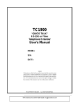
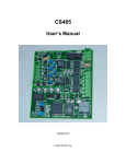
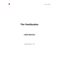
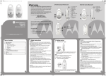
Technical Specifications BoardX Motherboard BoardX is a collection of electronic circuit boards that stack on top of one another to share resources, communicate, and extend the functionality of one another. This system is built on a motherboard that acts as both an electrical and structural foundation. • Free documentation and software • Easy connectivity • Unique shape and color Electrical Limits Max Voltage1 Max Power Dissipation (Ta = 25° C)5,6,7 Max DCVcc Dropout Voltage Unlike similar products (but much like a familiar PC system), the motherboard does not come with a processor pre-installed. Processors come as simple, lowcost, add-on boards, which allow any processor (or multiple processors) to be used with the system. Max 5.0V Dropout Voltage7 Add-ons can be attached to the USB, SPI, UART, and I2C buses to provide any feature imaginable. These can be sensors, communication interfaces, or even physical control devices such as motors or servos. With this idea in mind, a robust and flexible design can be achieved that allows you to choose which parts of the system to design and which parts to buy off the shelf. • Processor-independent hardware – the hardware is compatible with any processor, and even multiple processors • Choice of full-size add-ons, or cheaper, mini addons • Multiple, independent add-on sockets to reduce vertical growth to 1/3 that of Arduino • A breadboard is included on the motherboard for quick prototyping • Reverse power polarity and short circuit detection to protect projects against accidental misconnects • High current allowance permits direct powering of motors, servos and other power-hungry uses Traits Shared with Popular Brands • Stackable design • Arduino compatible • Open source October 2011 Max 3.3V Dropout Voltage7 0.28V+ 5.0V Dropout Max DCVcc Current2,8 4.9 A (DC + 5V + 3.3V) 2A 2 A (5V + 3.3V) 500 mA 800 mA Max 3.3V Current2,7 Max 5.0V Current2,4,7 Max USB Current3,7 Steady State Current4,6,7 Distinguishing Characteristics 14 VDC 10 W (Tc <= 25° C) 1 W (otherwise) 0.05 V / Amp (Trace resistance) + 0.35 V (Diode) 0.28V @ 500 mA Minimum 3.3V Input Voltage7 3.6 V Minimum 5.0V Input Voltage7 5.3 V Applied to DC Input. This is routed directly to the DCVcc signal on board and also powers the 5V and 3.3V linear regulators. 2 Pulsed, All current draws from DCVcc (or USBVcc). Meeting or exceeding this level for more than brief periods of time may result in overheating or instability in the linear regulators. 3 USB Current limiting, auto-resetting fuse triggers. at >500 mA. It heats up and increases resistance until current drops below threshold. 4 3.3V power passes through the 5V regulator, counting against its quota. 5 Ta = Ambient Temp. Tc = Conductor Temp. 6 For each linear regulator (5.0V and 3.3V) individually. 1 PRELIMINARY RELEASE Page 1 Technical Specifications 7 8 When regulated using the onboard linear regulators Unregulated Main Port Details Signaling and Time Limits Max Recommended Trace Bandwidth1 Max UART<->USB Baud2 100 MHz 3,000 kbps Theoretical, based on wavelength and bandwidth equations using measured board characteristics and recommendations for bus standards. Calculations are based on a round trip from one end of the board to the other and back for extra safety margin. 2 Max supported baud rate for UART to USB converter chip. The chip can be bypassed by cutting the highlighted traces on the back of the motherboard, which should increase this clock rate. *Calculated using component datasheets and supplemented with PCB Toolkit — www.saturnpcb.com 1 Physical Dimensions Width Length Height Weight Drill Hole Size 3.45 in (8.76 cm) 3.82 in (9.70 cm) ??.? in (??.? cm) ??.? oz (??.? g) .125 in (0.318 cm) Port Overview The Main Port is the primary location for add-on modules that supply complex functionality. It provides a large design area as well as connections to every major signal on the board. Signals 3V3, 5V, DCVcc GND !RESET USBM, USBP Secondary Add-on Ports are smaller and well-suited for simple things such as sensors or memory. Many of these can fit on the board simultaneously and can be made cheaply by the end user or third parties. October 2011 PRELIMINARY RELEASE Power Ground (Active Low) Reset Signal, driven low by reset button or other source. Do not drive, signal is normally at 3.3V Differential USB Bus data signals, Negative Polarity (USBM) and Positive (USBP) Page 2 Technical Specifications !DTR !RTS !CTS SCL, SDA TXD RXD (Active Low) Data Terminal Ready signal sent from USB host indicating it is ready to accept data. This is pulled low automatically by the USB to Serial converter chip on powerup. Connect this in series with a 0.1 μF capacitor to the !RESET signal and a host computer can do a remote reset (Active Low) Request to send signal, driven low by an MCU to indicate that data is ready to send (Active Low) Clear to send signal, driven low by host computer to indicate that data is ready to be received I2C Serial Clock and Serial Data lines tied to 3.3V through a 4.7K pull-up resistor. These should never be driven high, as they are open drain. Transmit data from an MCU or device Receive data going to an MCU or device !SS (Active Low) SPI Slave Select Line MOSI SPI Master Data Output MISO SPI Master Data Input SCK SPI Bus Clock October 2011 I/O 1 & 2 I/O 3 General Purpose I/Os (GPIOs) that are routed to all Add-on Port and Main Port devices. Use for any purpose. A GPIO routed to all Main Port devices, but not to Add-on Ports. Add-On Port Details Signals 3V3, 5V, DCVcc GND !RESET PRELIMINARY RELEASE Power Ground (Active Low) Reset Signal, driven low by reset button or other source. Do not drive, signal is normally at 3.3V Page 3 Technical Specifications USB-to-Serial Converter The BoardX Motherboard routes power and I/O on two layers, both of which contain ground planes. The ground planes are connected at various points by vias and device pins. Power signals are routed using a minimum trace width of 24 mils (0.024 in.). Multiple connections are made throughout the board to decrease the effective resistance in these traces. High current applications will find themselves limited not so much by trace resistance but by the restrictions made by other components on the board. The main power protection diode, for example, allows a constant current draw of 2-3 A, depending on ambient temperature. Signals !RTS !CTS !DTR TXD RXD MCU_TXD MCU_RXD Connections See !RTS See !CTS See !DTR See TXD See RXD Transmit data from an MCU Receive data going to an MCU TXD->MCU_RXD RXD->MCU_TXD 5V and 3.3V power is controlled by linear regulators. To simplify automatic switching between USB and DC power sources, 3.3V power cascades through the 5V regulator first, and then re-regulated down to 3.3V. If you need efficiency, see the section on Auxiliary Power. Double-regulation means that the current through the 3.3V regulator must be calculated as I5V + I3.3V. This applies to power dissipation as well. Auxiliary Power Power Distribution, Routing and Quiescent Power Consumption USB Powered ?? mA 5V DC Powered 9V DC Powered 12V DC Powered USB + 9V DC Powered ?? mA ?? mA ?? mA ?? mA USB + ?? mA DC Quiescent power consuption with no add-on modules. 1 October 2011 PRELIMINARY RELEASE Page 4 Technical Specifications BoardX has a few tricks up its sleeve. One of these is the ability to use a secondary power regulation system of your own choice, if the built-in linear regulators are not up to your application. Auxiliary power is activated by attaching DC or USB power in the usual fashion and leaving the on-off slide switch in the off position (labeled on the board as AUX). DC and USB Power are automatically made available on the pins labeled DC SEND and USB SEND respectively. The auxiliary power system’s ports are located around the onboard linear regulators. AUX signals should be connected to a separate system of regulation, maybe DC to DC, maybe something else; the choice is yours. A specific add-on board can also be made to fit the board and become self-contained. The breadboard is provided to assist you in your prototyping adventures. Simple tasks such as blinking LEDs, or even motor control and audio amplification will easily fit, becoming portable along with the rest of your project. Signals from any location on the board may be safely connected using solid gauge hookup wire. Additional power connectors are available along the perimeter, as they are the most commonly used. Fin. However you proceed, ensure 5V, 3.3V, and optionally DCVcc, are returned on their respective return lines. 5V and 3.3V must be present and have sufficient capacity for all onboard systems to operate properly. Be sure no signals are otherwise connected to these return lines; (as noted in the picture) any positive voltage above ~ 0.7V will disable the onboard power regulators. Auxiliary Power Board Width Length ??.? in (??.? cm) ??.? in (??.? cm) Breadboard Width Length Number of Positions October 2011 1.4 in (??.? cm) 1.8 in (??.? cm) 170 PRELIMINARY RELEASE Page 5