1
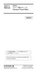
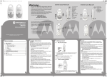
User’s
Manual
Model 701926
High Voltage Differential Probe for the
DL Series
The following symbols are used in this manual.
Improper handling or use can lead to injury to the user or damage to the instrument.
This symbol appears on the instrument to indicate that the user must refer to the
user’s manual for special instructions. The same symbol appears in the corresponding
place in the user’s manual to identify those instructions. In the manual, the symbol is
used in conjunction with the word “WARNING” or “CAUTION.”
WARNING Calls attention to actions or conditions that could cause serious or fatal injury to the
user, and precautions that can be taken to prevent such occurrences.
Thank you for purchasing the High Voltage Differential Probe (701926) for the DL Series. To ensure
correct use, please read this manual thoroughly before beginning operation.
After reading this manual, keep it in a safe place.
CAUTION Calls attention to actions or conditions that could cause light injury to the user or
Contact information of Yokogawa offices worldwide is provided on the following sheet.
• PIM113-01Z2 List of worldwide contacts
Note
damage to the instrument or the user’s data, and precautions that can be taken to
prevent such occurrences.
Calls attention to information that is important for proper operation of the instrument.
1.Description
5th Edition: November 2015 (YMI)
All Rights Reserved, Copyright © 2008, Yokogawa Electric Corporation
All Rights Reserved, Copyright © 2010, Yokogawa Meters & Instruments Corporation
Printed in Japan
This probe provides differential inputs to be used with oscilloscopes with single-ended inputs.
2.Configuration
The differential probe consists of the following parts and accessories.
IM 701926-01E
5th Edition
Approx. 90 cm
Approx. 50 cm
Safety Precautions
4
Make sure to observe the following safety precautions when handling the probe. YOKOGAWA assumes
no liability for the customer’s failure to comply with these safety precautions. Before you use the probe,
read the measuring instrument’s manual to fully aware of its specifications and handling.
2
Parts No
Black: B8099RC
Red: B8099RD
3. Ground extension lead (length: approx. 100 cm) 4. Power cable* (length: approx. 150 cm)
B9852MJ
* Power can be supplied from a YOKOGAWA measuring instrument, 700938, or 701934..
3.Probe Part Names
WARNING
Ground the measuring instrument
Make sure to connect the protective grounding terminal of the measuring instrument to
ground.
Stop use if you suspect damage
If you suspect that the probe is broken, consult your nearest YOKOGAWA dealer.
Observe the maximum input voltage
Do not apply voltage exceeding 7000 Vpeak between an input lead and ground or between
two input leads. The maximum input voltage is 7000 Vpeak regardless of whether 1000:1 or
100:1 attenuation is used.
Ground the probe
Ground the probe by connecting the grounding conductor of the measuring instrument’s
power cable or another appropriate grounding conductor to the BNC shell and an auxiliary
grounding terminal.
Before connecting the probe input terminal to the circuit under measurement, ensure that the
measuring instrument is grounded properly, that the probe output connector is attached to
the BNC connector of the measuring instrument, and that the auxiliary grounding terminal is
connected to a proper ground.
Do not remove the alligator clip’s cover
To prevent electric shock or fire, do not remove the alligator clip’s insulation cover.
Do not use in damp places
To prevent electric shock, do not use the probe in damp places.
Do not use in an explosive atmosphere
To prevent fire and injury, do not use the probe in a flammable or explosive atmosphere or
near steam.
Do not touch exposed circuitry
To prevent injury, remove metallic objects and jewelry such as rings and watches. Do not
touch exposed live connections or components.
Do not disassemble or modify
Do not disassemble or modify the product. YOKOGAWA assumes no liability if you
disassemble or modify the product.
CAUTION
Use the correct power supply
Power the probe by using four AA dry cells, by using a 6 VDC/200 mA or 9 VDC/150 mA
external power supply, or by connecting a probe power cable to the DL Series probe power
supply terminal, the 700938, or the 701934. Operating the probe while using a power supply
exceeding the specified voltage may cause damage to the instrument.
Turn OFF the probe when connecting an external power supply
Turn the probe power switch OFF when connecting or disconnecting from the external power
supply.
Do not install AA batteries when using an external power supply.
Conditions of use
This product has not been designed or manufactured for applications in which high reliability
is required over a long time period.
Operating environment limitations
This product is a Class A (for industrial environments) product. Operation of this product in
a residential area may cause radio interference in which case the user will be required to
correct the interference.
Waste Electrical and Electronic Equipment
Waste Electrical and Electronic Equipment (WEEE), Directive
(This directive is valid only in the EU.)
This product complies with the WEEE directive marking requirement. This marking
indicates that you must not discard this electrical/electronic product in domestic
household waste.
Product Category
With reference to the equipment types in the WEEE directive, this product is classified
as a “Monitoring and control instruments” product.
When disposing products in the EU, contact your local Yokogawa Europe B.V. office.
Do not dispose in domestic household waste.
Authorized Representative in the EEA
Yokogawa Europe B.V. is the authorized representative of Yokogawa Meters & Instruments Corporation
for this product in the EEA. To contact Yokogawa Europe B.V., see the separate list of worldwide
contacts, PIM 113-01Z2.
3
Standard parts
1. Probe
2. High voltage alligator clip (Two in a set)
The following symbols are used on this instrument.
Warning: handle with care. Refer to the user’s manual or service manual. This symbol
appears on dangerous locations on the instrument which require special instructions for
proper handling or use. The same symbol appears in the corresponding place in the manual
to identify those instructions.
Risk of electric shock
Make sure to observe the following safety precautions to prevent electric shock, personal
injury, or damage to the instrument.
1
ADJUST (DC offset adjustment)
Attenuation ratio selector
Power LED
Power switch
BNC output connector
4. Installing or Replacing Batteries
Slide the lid on the back side of the probe, and install or replace the four AA dry cells.
The probe is shipped from the factory without the batteries installed.
5.Procedure
1. Connect the provided high voltage alligator clips to the probe input leads.
2. Supply power to the probe by one of the following methods.
• Install four AA cells.
The power LED blinks if the battery level goes low. If this message appears, replace the dry
cells.
• Connect the appropriate power cable to an external power supply.
• Connect the probe power cable to a probe power supply terminal on the DL Series, the
700938, or the 701934.
3. Connect the BNC output connector to the oscilloscope input terminal, and properly ground the
auxiliary ground terminal. If necessary, use the auxiliary ground extension lead.
4. Turn the power switch ON, and warm up the probe for at least 30 minutes.
5. Select the appropriate attenuation using the attenuation ratio selector.
•For higher resolution and less noise when measuring signals less than or equal to 700 V,
switch the attenuation to 1/100.
• When measuring signals greater than 700 V, set the attenuation to 1/1000.
6. If the offset voltage is large, short the alligator clips, and turn the ADJUST variable resistor (DC
voltage adjustment) using an appropriate flat-head screwdriver to adjust the offset voltage.
7. Connect the two probe input leads to the two points of measurement (differential measurement).
The performance declines if you only connect a probe input lead to a single point. Make sure to
connect both leads.
WARNING
• To prevent electric shock and other accidents, make sure to connect the probe output
to the properly grounded oscilloscope so that the ground end (shielded end of the BNC
connector) of the output cable is grounded.
• Turn OFF the power to the circuit under measurement when connecting or disconnecting
the probe from the circuit under measurement. Connecting or removing the probe while
the power is ON is dangerous. Do not touch the probe after turning ON the power to the
circuit under measurement. Do not remove the probe from the measuring instrument
while the probe is connected to the circuit under measurement.
• When disconnecting the probe BNC output connector, first turn OFF the power to the
circuit under measurement. Then, disconnect the probe from the high voltage parts of the
circuit under measurement.
• When replacing batteries or connecting an external power supply, first turn OFF the
power to the circuit under measurement. Then, remove the input lead from the circuit
under measurement.
CAUTION
• This probe is designed to measure the voltage difference between two points on the
circuit under measurement. It does not electrically isolate the circuit under measurement
from the measuring instrument.
• Use a soft cloth to clean the probe. Be careful not to break the probe. Do not immerse
the probe in liquid or use abrasive cleaners on the probe. Do not use benzene or other
solvents on the probe.
• Turn the probe power switch OFF when connecting or disconnecting from the external
power supply. Do not install AA batteries when using an external power supply.
Note
• Accurate measurements may not be possible near objects with strong electromagnetic fields
such as transformers, large current circuits, and wireless equipment.
• Before use, flip the attenuation switch back and forth several times. The switch’s electrical
contacts can weaken if not used for long periods of time.
• To take accurate measurements, we recommend that you calibrate the probe once a year.
IM 701926-01E 1/2
6.Specifications
Item
Frequency bandwidth1, 2
Input type
Attenuation
Output offset voltage 2, 3
Input resistance and capacitance
(typical) 4
Allowable differential voltage
(between + and – terminals)
Allowable common mode voltage
Maximum input voltage
(to ground) 5
CMRR (typical) 1, 4
Output voltage 1, 2
Output impedance
Gain accuracy 1, 2, 3
Operating conditions
Storage conditions
Operating altitude
Storage altitude
Power requirements 6
Battery life
Warm-up time
Recommended calibration period
External dimensions
Weight
Safety
Complying
standards
standards
Emission
Complying
standards
Immunity
Complying
standards
Specifications
DC to 50 MHz (–3 dB)
Balanced differential input
1000:1 or 100:1, switchable
±5 mV or less (after adjusting the ADJUST resistor)
50 MΩ + approx. 17 pF (parallel with respect to ground)
5000 V rms or less and 7000 Vpeak or less at 1000:1
attenuation
500 V rms or less and 700 Vpeak or less at 100:1 attenuation
5000 Vrms or less and 7000 Vpeak or less
1000 Vrms CAT III
5000 Vrms or 7000 Vpeak CAT I
–80 dB or less at 60 Hz, –60 dB or less at 20 kHz
±7 V (DC+ACpeak) Value when the probe is used in
combination with a measuring instrument whose input
resistance is 50 kΩ or higher
Used on a 1 MΩ input oscilloscope
±2%
5 to 40°C, 25 to 85%RH (no condensation)
–30 to 70°C, 25 to 85%RH (no condensation)
2000 m or less
3000 m or less
•Internal battery: Four AA dry cells
•External power supply: 6 VDC/200 mA or higher or 9
VDC/150 mA or higher, with a positive center pin.
•Power is supplied through the dedicated cable B9852MJ
from a YOKOGAWA measuring instrument’s probe power
supply terminal or from a 700938 or 701934 probe power
supply.
Approx. 7 hours under continuous use (when using alkaline
dry cells)
At least 30 minutes
1 year
202 mm × 83 mm × 38 mm (excluding connector and cable)
Approx. 500 g (excluding batteries)
Probe (excluding the alligator clip)
EN61010-031
Measurement category III 7 1000 Vrms
Measurement category I 8 5000 Vrms, 7000 Vpeak
Pollution degree 2 9
Alligator clip (B8099RC/8099RD)
EN61010-031
Measurement category I 8 5000 Vrms, 7000 Vpeak
Pollution degree 2 9
Probe and alligator clip 10
EN61010-031
Measurement category I 8 5000 Vrms, 7000 Vpeak
Pollution degree 2 9
EN61326-1 Class A
EN55011 Class A, Group 1
EMC standards of Australia and New Zealand EN55011
Class A, Group 1
This product is a Class A (for industrial environment)
product. Operation of this product in a residential area
may cause radio interference in which case the user is
required to correct the interference.
EN61326-1 Table 1
Max input voltage
1 When the supply voltage from the dry cells is 5 V or higher or when using an external power
supply.
2 At an ambient temperature 23±5°C, humidity 55% ± 10% RH, 30 minutes after the power is
turned on.
3 The accuracy is the total of the gain accuracy and offset voltage.
4 Typical values are typical or mean values. They are not strictly guaranteed.
5 Frequency derating (load reduction) applies.
Input voltage derating
10000
1000
5000
2500
200
100
10
20
1M
Frequency(Hz)
10M
100M
6 The power LED blinks if the battery level goes low. If this message appears, replace the dry
cells.
When using an external power supply, do not install dry cells.
7 This equipment is for measurement category III (CAT III). Do not use it with measurement
category IV (CAT IV). CAT III applies to measurement of the distribution level, that is, building
wiring, fixed installations. CAT IV applies to measurement of the primary supply level, that is,
overhead lines, cable systems, and so on.
8 Measurement category (CAT I) applies to measurement of circuits that are not directly connected
to a main power source. Forexample, this category applies to measurement of secondary electric
circuits in equipment across a transformer. The estimatedtransient overvoltage for the 701926 is
0 V.
9 Pollution degree applies to the degree of adhesion of a solid, liquid, or gas which deteriorates
withstand voltage or surface resistivity. Pollution degree 2 applies to normal indoor atmospheres
(with only non-conductive pollution).
10When using devices with different measurement categories, the lower measurement category
applies.
For this probe, because the measurement category of the alligator clip is lower, when the probe
and the alligator clip are used together, measurement category I (CAT I) applies.
To use the probe under measurement category III conditions, use it with the 701954 alligator clip
(1000 Vrms, CAT III, sold separately).
IM 701926-01E 2/2