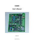
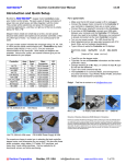
1
Embedded Modbus TCP Module EMT-331Lite User Manual REV 1.1 SiboTech Automation Co., Ltd Technical support: +86-21-5102 8348 E-mail: [email protected] EM T - 3 3 1 Lite Embedded Modbus TCP Module User Manual Table of Contents 1 About the Embedded Module ........................................................................................................... 3 1.1 General..........................................................................................................................................................3 1.2 Features .........................................................................................................................................................3 1.3 Specifications................................................................................................................................................3 2 Hardware ........................................................................................................................................... 5 2.1 Appearance ...................................................................................................................................................5 2.2 Indicators ......................................................................................................................................................5 2.3 Interface ........................................................................................................................................................5 2.3.1 Ethernet Interface...............................................................................................................................5 2.3.2 Host Interface.....................................................................................................................................6 2.4 UART Baud Rate ..........................................................................................................................................7 2.5 Reset Signal ..................................................................................................................................................8 3 Modbus TCP to Modbus RTU .......................................................................................................... 9 3.1 Description....................................................................................................................................................9 3.2 The Flowchart of User Program ...................................................................................................................9 3.3 Real-time monitoring IP function ...............................................................................................................10 3.4 Transmit the Setting IP Address Message ................................................................................................... 11 4 Modbus TCP to SiboTech-defined Protocol ................................................................................... 14 4.1 Description..................................................................................................................................................14 4.2 The Flowchart of User Program .................................................................................................................15 4.3 Real-time monitoring IP function ...............................................................................................................17 4.4 Transmit the Setting IP Address Message ...................................................................................................17 4.5 SiboTech-defined Protocol .........................................................................................................................19 5 IP Address Report ........................................................................................................................... 21 6 Dimension ....................................................................................................................................... 23 7 Development Board ........................................................................................................................ 25 7.1 Appearance .................................................................................................................................................25 7.2 Function ......................................................................................................................................................25 7.2.1 RS232 Interface ...............................................................................................................................25 7.2.2 Baudrate Setting Switch...................................................................................................................26 7.2.3 Reset Key .........................................................................................................................................27 7.2.4 LED .................................................................................................................................................27 8 Configuration Software ................................................................................................................... 28 8.1 Overview ....................................................................................................................................................28 8.2 Search Equipment .......................................................................................................................................29 8.2.1 Search All Equipments of Ethernet ..................................................................................................29 8.2.2 IP Search ..........................................................................................................................................30 8.3 Advanced Configuration .............................................................................................................................31 8.3.1 Ethernet Parameters .........................................................................................................................33 8.3.2 Password ..........................................................................................................................................34 8.3.3 IP Address Report ............................................................................................................................35 www.sibotech.net/en 1 R EM T - 3 3 1 Lite Embedded Modbus TCP Module User Manual 8.3.4 Advanced Parameter ........................................................................................................................36 8.4 Configuration ..............................................................................................................................................37 8.4.1 Ethernet Parameters .........................................................................................................................38 8.4.2 Password ..........................................................................................................................................39 8.4.3 IP Address Report ............................................................................................................................40 8.5 OK, Cancel and Help ..................................................................................................................................40 8.5.1 OK ...................................................................................................................................................41 8.5.2 Cancel ..............................................................................................................................................42 8.5.3 Help .................................................................................................................................................42 8.6 IP Address Report .......................................................................................................................................43 8.6.1 Parameter configuration ...................................................................................................................44 8.6.2 IP Address Report ............................................................................................................................45 8.7 New.............................................................................................................................................................45 8.8 Open............................................................................................................................................................47 8.9 Save ............................................................................................................................................................47 9 Test Software (EemTest) ................................................................................................................. 50 9.1 Overview ....................................................................................................................................................50 9.2 User Interface..............................................................................................................................................50 9.3 Establish/Disconnect Connection ...............................................................................................................51 9.4 Set Work Mode ...........................................................................................................................................54 9.5 Receive/Transmit Data................................................................................................................................56 www.sibotech.net/en 2 R EM T - 3 3 1 Lite Embedded Modbus TCP Module User Manual 1 About the Embedded Module 1.1 General EMT-331Lite is an embedded Modbus TCP module and provides instant Modbus TCP connectivity via the host interface which is SiboTech defined. Any device that supports the host interface can communicate with EMT-331Lite through UART. 1.2 Features Upgrade your UART or serial device to Modbus TCP device expediently Provide two kinds of operating modes Modbus TCP to Modbus RTU: transparent mode Modbus TCP to SiboTech-defined protocol: data mapping mode Ethernet is 10/100M adaptive Supports 4 Modbus TCP connects at most Can cache 20 Modbus TCP request messages at most in Modbus TCP to Modbus TRU mode Configuration software EMT-123 Setting the IP address via the UART( Optional Features), refer to chapter 7 1.3 Specifications Modbus TCP to Modbus RTU mode: Can cache 20 request messages at most; When the request messages buffer overflows, it can discard the current request. Modbus TCP to SiboTech-defined protocol mode: Support function codes: 04H、03H、06H、10H The size of input and output buffers can be set by users: The size of input buffer is 256 bytes at most www.sibotech.net/en 3 R EM T - 3 3 1 Lite Embedded Modbus TCP Module User Manual The size of output buffer is 256 bytes at most The host interface is UART, half duplex, 8 data bits, one stop bit, and no parity, and support 9600, 19200, 38400, 57600, 115200, 230400 baud rate Power: +3.3VDC (3.14 ~ 3.45V), 182mA Environmental temperature: -40 ~ 85℃, humidity: 5% ~ 90% Dimension: 38.3mm (Length)*23mm (Width)*21.5mm (Height) www.sibotech.net/en 4 R EM T - 3 3 1 Lite Embedded Modbus TCP Module User Manual 2 Hardware 2.1 Appearance Network activity indicator Network indicator connecting 2.2 Indicators Indicator Status Description Off No network connection Always on Have network connection Off No network data transmitting or receiving Blinking Have network data transmitting or receiving Green Yellow 2.3 Interface 2.3.1 Ethernet Interface www.sibotech.net/en 5 R EM T - 3 3 1 Lite Embedded Modbus TCP Module User Manual Pin 1 Pin 8 The Ethernet interface uses an 8-line RJ-45 interface,and the pin definitions are as follows: Pins Signals Descriptions Pin 1 TXD+ Transmit Data+ Pin 2 TXD- Transmit Data- Pin 3 RXD+ Receive Data+ Pin 4 BID+ Bi-directional Data+ Pin 5 BID- Bi-directional Data- Pin 6 RXD- Receive Data- Pin 7 BID+ Bi-directional Data+ Pin 8 BID- Bi-directional Data- 2.3.2 Host Interface EMT-331Lite has a 20-pin socket connector (needle-type), including power, UART and GPIO. The pin position and definition are as follows: www.sibotech.net/en 6 R EM T - 3 3 1 Lite Embedded Modbus TCP Module User Manual Pins Signals Description 1~ NC Reserved 6 7 RXD UART Receive (Input), connect with TXD of host processor or MCU 8 TXD UART Transmit (Output), connect with RXD of host processor or MCU 9 NC Reserved The status of EMT-331Lite (Output), and need a 10K pull-up resistor on user board. Logic 1: The EMT-331Lite module is in starting. Logic 0: The module’s start has been completed. 10 /RUN If this pin is pull down to low voltage before starting the module(by using a 1K pull-down resistor), the module will start with default IP address (192.168.0.11), and this mode is used to update the firmware of EMT-331Lite. 11 BAUD2 12 BAUD1 13 BAUD0 14 /RESET 15 +3.3V +3.3V DC power Supply 16 GND GND power Supply Set the UART baud rate (Input), see the following table. Reset signal (Input), Active low. 17 ~ NC Reserved 19 Data Exchange(Output), and need a 10K pull-up resistor on the user board. Logic 1: The module is in non-data exchange state (such as start state, waiting for 20 /DATAEXCH initialization state that waits users to send messages to initialize, start the TCP protocol stack, etc.) Logic 0: The module is ready for data exchange. 2.4 UART Baud Rate UART baud rate settings are as follows: www.sibotech.net/en 7 R EM T - 3 3 1 Lite Embedded Modbus TCP Module User Manual Index BAUD2 BAUD1 BAUD0 Baud Rate(bps) 0 0 0 0 Reserved, don’t use 1 0 0 1 Reserved, don’t use 2 0 1 0 9600 3 0 1 1 19200 4 1 0 0 38400 5 1 0 1 57600 6 1 1 0 115200 7 1 1 1 230400 2.5 Reset Signal EMT-331Lite RESET (Pin 14) is hardware reset signal input. When the RESET pin is pulled down to GND or low to 2.88V lasting for 1 millisecond, the module will be forced to reset, and the host must wait for 250 milliseconds (typical value,after reset the module), and then the host must check the PIN10 (/RUN) and PIN20 (/ DATAEXCH). If the two pins are Logic 0, then the host can exchange data. www.sibotech.net/en 8 R EM T - 3 3 1 Lite Embedded Modbus TCP Module User Manual 3 Modbus TCP to Modbus RTU 3.1 Description EMT-331Lite acts as a Modbus TCP server at the Ethernet side, and a Modbus RTU master at the serial port side. EMT-331Lite receives Modbus TCP request messages come from Ethernet, then convert the message format from TCP to RTU, and send them to the serial port. RTU response messages receiving from the serial port are converted to Modbus TCP response messages and are transmitted to corresponding Modbus TCP master. The procedure of message transmission is as follows: Modbus TCP Modbus RTU Request1 Request 2 Request… Request 1 Response 1 Response1 Request 2 EMT-331Lite Response 2 Response 2 Request… Response… Response… Every Modbus TCP can connect multiple requests at the same time in this mode, and all connections share the request buffer which can cache 20 frames. 3.2 The Flowchart of User Program www.sibotech.net/en 9 R EM T - 3 3 1 Lite Embedded Modbus TCP Module User Manual The flow chart of using configuration software (EMT-123) setting EMT331'IP address mode: The flow chart of using UART setting EMT-331'IP address mode: Start Start 1 1 Read the status of the /RUN pin Read the status of the /DataExch pin 0 0 Transmit the setting IP address message Ready to receive Modbus RTU request Receive correct response Start Modbus RTU communication 1 Read the status of the /DataExch pin 0 Ready to receive Modbus RTU request Start Modbus RTU communication 3.3 Real-time monitoring IP function If the EMT-331Lite is set to DHCP,then the module will monitor its IP when it is running.If IP changed,it will pull up /DataExch pin to logic 1.Then two cases: 1.Using configuration software setting IP address mode: The www.sibotech.net/en 10 R EM T - 3 3 1 Lite Embedded Modbus TCP Module User Manual module will obtain an IP again.User needs to read / DataExch pin state. If it re-becomes logic 0, indicating that the module has obtained IP,and the module can begin to communicate; 2.Using UART setting IP address mode: EMT-331Lite will wait the user to send the setting IP address message, and the next step is the same with the first initialization. 3.4 Transmit the Setting IP Address Message When using UART to set the module IP address, user board (host) is the communication initiator, and EMT-331Lite responses.The module waits until it receives the setting IP address message. EMT-331Lite reads these pins BAUD0, BAUD1 and BAUD2 that select The UART baud rate when it power on or reset. 1. Request message--- (user board->module) Byte Modbus TCP to Modbus RTU Mode 0 message length is 17 which includes all following bytes except the check sum byte and the length 1 byte , high-byte first 2 Reserved, always 0 3 IP Configuration Mode, 0: Static Configuration; 1: DHCP 4 5 IP Address, high-byte first 6 7 8 9 Subnet Mask, high-byte first 10 11 12 13 Default Gateway Address, high-byte first 14 www.sibotech.net/en 11 R EM T - 3 3 1 Lite Embedded Modbus TCP Module User Manual 15 16 Reserved, always 0 17 Reserved, always 0 18 Reserved, always 0 19 Check sum, byte 0+byte 1+…+byte 18 2. Response message--- (module->user board) Byte Correct Response Incorrect Response 0 Data length is 2 Data length is 2 1 0: Correct Error code (not 0) 2 0 Extra error code 3 Check sum, byte 0+byte 1+byte 2 Check sum, byte 0+byte 1+byte 2 3. Error code 4. Index Error Code Explanation 0 1 Check sum error. 1 2 Data length error. 2 3 IP configuration mode does not exist. Extra error code is always 0xFF. EMT-331Lite also has sending IP address reporting function(via UART).To enable the function, you must meet the following two conditions: 1. The module is set to DHCP; 2. In the above request message table, the Byte 2 is set to 0x01; After the user transmits the setting IP address message, the user will receive "0x2E" per second, until the EMT-331Lite successfully obtain an IP address. Then the user will receive a message,and its format is shown as follows: IP Address Report IP Address Report Byte 0 message length is 12 which includes all following bytes except the check sum byte and the length byte , high-byte first 1 2 www.sibotech.net/en IP Address,high-byte first 12 R EM T - 3 3 1 Lite Embedded Modbus TCP Module User Manual 3 4 5 6 7 Subnet Mask, high-byte first 8 9 10 11 Default Gateway Address, high-byte first 12 13 Eg:0C C0 A8 00 BB FF FF FF 00 Check sum, byte 0+byte 1+…+byte 12 C0 A8 00 01 95 The first byte is the length. The length does not include length of checksum. The each next four bytes are IP address, subnet mask, and gateway address. Last byte is checksum. www.sibotech.net/en 13 R EM T - 3 3 1 Lite Embedded Modbus TCP Module User Manual 4 Modbus TCP to SiboTech-defined Protocol 4.1 Description EMT-331Lite acts as a Modbus TCP server at the Ethernet side, and the serial protocol is SiboTech-defined protocol. Modbus TCP communication and serial communication of EMT-331Lite are independent, and exchange data between through the input and output data buffer inside EMT-331Lite. User board can exchange data with EMT331 according to the SiboTech –defined protocol of EMT-331Lite. The procedure of message transmission is as follows: Modbus TCP SiboTech-defined protocol Request1 Request a Response1 Response a Request2 Request b EMT-331Lite Response2 Response b Request… Request … Response… Response… In this mode, Modbus TCP only supports 03H、04H、06H、10H function codes. Note:In this mode,each Modbus TCP client just transmits one request message,and do not transmits another request message until the Modbus TCP client receives the response or the response timeout. The corresponding relationship of data buffer and function codes is as follows: www.sibotech.net/en 14 R EM T - 3 3 1 Lite Embedded Modbus TCP Module User Manual 04H Function Code Input Data Buffer 06H Function Code 10H Function Code Output Data Buffer 03H Function Code 04H function code is used to read input data; 06H and 10H function codes are used to write output data; 03H function code is used to read back output data, and then multiple Modbus TCP masters can exchange data using this function code. 4.2 The Flowchart of User Program www.sibotech.net/en 15 R EM T - 3 3 1 Lite Embedded Modbus TCP Module User Manual The flow chart of using configuration software (EMT-123) setting EMT331'IP address mode: The flow chart of using UART setting EMT-331'IP address mode: Start Start 1 1 Read the status of the /RUN pin Read the status of the /DataExch pin 0 0 Transmit the setting IP address message Ready to receive Modbus RTU request Receive correct response Start Modbus RTU communication 1 Read the status of the /DataExch pin 0 Ready to receive Modbus RTU request Start Modbus RTU communication www.sibotech.net/en 16 R EM T - 3 3 1 Lite Embedded Modbus TCP Module User Manual 4.3 Real-time monitoring IP function If the EMT-331Lite is set to DHCP,then the module will monitor its IP when it is running.If IP changed,it will pull up /DataExch pin to logic 1.Then two cases: 1.Using configuration software setting IP address mode: The module will obtain an IP again.User needs to read / DataExch pin state. If it re-becomes logic 0, indicating that the module has obtained IP,and the module can begin to communicate; 2.Using UART setting IP address mode: EMT-331Lite will wait the user to send the setting IP address message, and the next step is the same with the first initialization. 4.4 Transmit the Setting IP Address Message When using UART to set the module IP address, user board (host) is the communication initiator, and EMT-331Lite responses. The module waits until it receives the setting IP address message. EMT-331Lite reads these pins BAUD0, BAUD1 and BAUD2 that select The UART baud rate when it power on or reset. 1. Request message--- (user board->module) Byte Modbus TCP to SiboTech-defined Protocol 0 Data length is17 which includes all following bytes except the check sum byte and the length byte, 1 high-byte first 2 Always 0, except in one case which refer to chapter 4.3 3 IP Configuration Mode, 0: Static Configuration; 1: DHCP 4 5 IP Address, high-byte first 6 7 8 9 Subnet Mask, high-byte first 10 11 www.sibotech.net/en 17 R EM T - 3 3 1 Lite Embedded Modbus TCP Module User Manual 12 13 Default Gateway Address, high-byte first 14 15 16 Reserved, always 0 17 Reserved, always 0 18 Reserved, always 0 19 Check sum, byte 0+byte 1+…+byte 18 2. Response message--- (module->user board) byte Correct Response Incorrect Response 0 Data length is 2 Data length is 2 1 0: Correct Error code (not 0) 2 0 Extra error code 3 Check sum, byte 0+byte 1+byte 2 Check sum, byte 0+byte 1+byte 2 3. Error code Index Error Code Explanation 0 1 Check sum error. 1 2 Data length error. 2 3 IP configuration mode does not exist. 4. Extra error code is always 0xFF EMT-331Lite also has sending IP address reporting function(via UART).To enable the function, you must meet the following two conditions: 1. The module is set to DHCP; 2. In the above request message table, the Byte 2 is set to 0x01; After the user transmits the setting IP address message, the user will receive "0x2E" per second, until the EMT-331Lite successfully obtain an IP address. Then the user will receive a message,and its format is shown as follows: IP Address Report IP Address Report Byte 0 message length is 12 which includes all following bytes except the check sum byte and the length www.sibotech.net/en 18 R EM T - 3 3 1 Lite Embedded Modbus TCP Module User Manual byte , high-byte first 1 2 IP Address,high-byte first 3 4 5 6 Subnet Mask, high-byte first 7 8 9 10 11 Default Gateway Address, high-byte first 12 13 Eg:0C C0 A8 00 BB FF FF FF 00 Check sum, byte 0+byte 1+…+byte 12 C0 A8 00 01 95 The first byte is the length. The length does not include length of checksum. The each next four bytes are IP address, subnet mask, and gateway address. Last byte is checksum. 4.5 SiboTech-defined Protocol User board is the communication initiator, and EMT-331Lite responses. The request messages contain input data, and the response messages contain output data. The communication process is as follows: 1. Request message (user board -> module) www.sibotech.net/en 19 R EM T - 3 3 1 Lite Embedded Modbus TCP Module User Manual Byte Description 0 message length includes all following bytes except the check sum byte , high-byte first 1 2 … Input data, high-byte first n Check sum, byte 0+byte 1+…+byte n n+1 2. Response message of SiboTech-defined protocol (module -> user board) Byte Correct response Byte Incorrect response 0 message length includes all following bytes except the 0 0x80 1 check sum byte , high-byte first 1 Data length is2 2 Error code 3 Extra error code 2 … Output data, high-byte first Check sum, byte 0+byte n 4 1+byte 2+byte3 Check sum, byte 0+byte 1+…+byte n n+1 3. 4. Error code Index Error code Description 0 1 Check sum error 1 2 Data length error Extra error code is always 0xFF. www.sibotech.net/en 20 R EM T - 3 3 1 Lite Embedded Modbus TCP Module User Manual 5 IP Address Report This feature allows EMT-331Lite sending the IP address report to the user's IP address,with user's cycle. Open configuration software,search EMT-331Lite,then open the configuration or the advanced configuration.And open IP Address Report,As shown below: Select ―Enable‖,enter the IP address and port number of terminal (Eg:computer) which receives reports. NOTE:The terminal must be EMT-331Lite's IP address in the same network segment! Fill in ―Auto Report Period‖.Download to EMT-331Lite and restart to use the function. The following table is the packet format of IP Address Report. Index High Byte 0 ―Sibo‖ 1 ―Tech‖ 2 Length of Data Low Byte 3 4 ―EMT-331Lite‖ 5 6 7 Serial Number 8 Firmware Major Version Number www.sibotech.net/en Firmware Minor Version Number 21 R EM T - 3 3 1 Lite Embedded Modbus TCP Module User Manual 9 MAC Address 10 MAC Address 11 IP Address 12 Subnet Mask 13 Gateway Address Always 0 14 15 16 Custom Name 17 18 www.sibotech.net/en 22 R EM T - 3 3 1 Lite Embedded Modbus TCP Module User Manual 6 Dimension Unit: [mm] Front: www.sibotech.net/en 23 R EM T - 3 3 1 Lite Embedded Modbus TCP Module User Manual Side: PCB dimension: www.sibotech.net/en 24 R EM T - 3 3 1 Lite Embedded Modbus TCP Module User Manual 7 Development Board 7.1 Appearance 7.2 Function 7.2.1 RS232 Interface RS232 interface is DB9 pin-connector, the description show as follow: Pin Signal Description 2 RX Connect with pin TX of RS232 of PC 3 TX Connect with pin RX of RS232 of PC 5 GND Connect with pin GND of RS232 of PC DB9 hole-connector crossover cable must be used when connect the board with RS232 interface of PC: RX Development board TX RS232 interface 2 2 RX PC 3 3 TX RS232 interface 5 5 GND GND www.sibotech.net/en 25 R EM T - 3 3 1 Lite Embedded Modbus TCP Module User Manual 7.2.2 Baudrate Setting Switch The 4-bit DIP switch on the development board is used to set the serial (UART) baud rate and default IP address locking: ON 1 0 1 Low bit 2 3 4 Middle High Default IP bit bit address locking Corresponding relationship of baud rate is as follows: Index High bit Middle bit Low bit Corresponding baud rate (bps) 0 0 0 0 Reserve 1 0 0 1 Reserve 2 0 1 0 9600 3 0 1 1 19200 4 1 0 0 38400 5 1 0 1 57600 6 1 1 0 115200 7 1 1 1 230400 The baud rate showing in the picture is 115200bps. The fourth bit of DIP is ―Default IP address locking‖ bit. When the bit is ―ON‖, the module starts the embedded Web Server with default IP configurations, which can be open with IE browser on the PC to restore default configurations or to update the firmware. However it can’t exchange data between the host and Modbus TCP. The default IP configurations are as follows: IP address: 192.168.0.11 Subnet mask: 255.255.255.0 www.sibotech.net/en 26 R EM T - 3 3 1 Lite Embedded Modbus TCP Module User Manual Default gateway: 192.168.0.1 7.2.3 Reset Key The key on the development board is the reset key, which is used to manual reset EMT-331Lite. 7.2.4 LED There are six indicators on the development board, and the description is as follows: Ind Name Description ex Power indicator, 0 Power On: Power on; Off: Power off 1 RTS Reserve EMT-331Lite’UART transmits indicator; 2 TX Blinking: EMT-331Lite’UART is transmitting data; Off: EMT-331Lite’UART isn't transmitting data. EMT-331Lite’UART receives indicator. 3 RX Blinking: EMT-331Lite’UART is receiving data; Off: EMT-331Lite’UART isn't receiving data. EMT-331Lite status indicator, 4 Run On: In run status; Off: In start-up status. EMT-331Lite data-interchange indicator, 5 DataExch On: In data-exchange status; Off: Not in data-exchange status. www.sibotech.net/en 27 R EM T - 3 3 1 Lite Embedded Modbus TCP Module User Manual 8 Configuration Software Put the product CD into the computer CD drive, open the CD, and install the configuration software EMT-123. Follow the prompts to complete the installation. Then open the configuration software and finish the configuration of EMT-331Lite. System Requirements: · PC with 1 GHz processor or higher · Windows® XP/Windows® 7 · Free disk space: min. 130 M Byte · CD ROM drive · RAM: min. 256 M Byte, recommended 512 M Byte · Keyboard and Mouse Note: The manufacturer default settings of EMT-331Lite are 192.168.0.11, subnet mask is 255.255.255.0, and default gateway is 192.168.0.1. 8.1 Overview EMT-123 is a product based on Windows platform, and is used to configure parameters of EMT-331Lite. Before running the software, make sure the computer and EMT-331Lite have been configured in the same network. Double click the icon to run the EMT-123 and its main window will appear: www.sibotech.net/en 28 R EM T - 3 3 1 Lite Embedded Modbus TCP Module User Manual 8.2 Search Equipment Before parameters configuration of EMT-331Lite, you need to search the equipment. The software provides two ways to search the equipment. Followings are the two ways. 8.2.1 Search All Equipments of Ethernet Click ―Search Equipment‖ button in the main window, the software will search all of the available EMT-331Lite equipments and list them in the table on the right side. www.sibotech.net/en 29 R EM T - 3 3 1 Lite Embedded Modbus TCP Module User Manual 8.2.2 IP Search Click ―IP Search‖ button in the main window, and there will be popping up a dialog box: www.sibotech.net/en 30 R EM T - 3 3 1 Lite Embedded Modbus TCP Module User Manual After entering the wanted IP address, click OK, the software will search EMT-331Lite with the named IP address in the network, and list the information of the equipment in the table. Note: If you have selected ―IP Search‖, correct IP address is needed; otherwise, it will search for nothing. 8.3 Advanced Configuration www.sibotech.net/en 31 R EM T - 3 3 1 Lite Embedded Modbus TCP Module User Manual Select one equipment in the right table, then ―Configuration‖, ―Advanced Configuration‖ and ―Save‖ buttons will become available: Click ―Advanced Configuration‖ button, a password dialog box will pop up if the equipment has been set up with a password; The Advanced Configuration window will appear when your entering password is correct. Note: If the module has a user password, column "Password" of the table will show "Required", otherwise, it will show "None" even if the module has an administrator password. www.sibotech.net/en 32 R EM T - 3 3 1 Lite Embedded Modbus TCP Module User Manual If the equipment has no password setting, you can directly enter the Advance Configuration window: 8.3.1 Ethernet Parameters Ethernet parameters include: ―Name‖, ―IP Configuration Mode‖, ―IP Address‖, ―Subnet Mask‖, ―Default Gateway‖, ―DNS1‖, and ―DNS2‖. www.sibotech.net/en 33 R EM T - 3 3 1 Lite Embedded Modbus TCP Module User Manual Name——Enter a name to identify the EMT-331Lite module; IP Configuration Mode——Set the device's IP address configuration mode; IP Address——Set the device's IP address; Subnet Masks——Set the subnet mask of the device; Default Gateway——Set the default gateway address of the device; DNS1——0.0.0.0 (currently only support 0.0.0.0) DNS2——0.0.0.0 (currently only support 0.0.0.0) Note: The name’s max length is 20 characters and cannot have spaces. 8.3.2 Password You can set up user password and admin password in this part. After entering the password, you need to confirm it, otherwise, there will display an alert box: www.sibotech.net/en 34 R EM T - 3 3 1 Lite Embedded Modbus TCP Module User Manual 8.3.3 IP Address Report Select check box before the ―Enable‖ , the parameters can be configured: Auto Report To ----- Set the remote Auto IP report server’s IP address and UDP port; Auto Report Period ----- The time interval between two IP report messages www.sibotech.net/en 35 R EM T - 3 3 1 Lite Embedded Modbus TCP Module User Manual 8.3.4 Advanced Parameter How to set the module's IP address Setting the IP address via software EMT-123 Setting the IP address via the host interface (UART) Note: When choosing "Setting the IP address via the host interface", EMT-331Lite will not initialize it's Ethernet until "Transmit the setting IP address message" is correct. Work Mode: There are two kinds of work modes: ―Modbus RTU‖ and ―SiboTech-defined protocol‖. In ―Modbus RTU‖ mode, you need to set ―Response Timeout‖ and ―Delay between Polls‖. Response Timeout-----The maximum time between the beginning of sending requests by the UART and receiving response completely, and the range is 10ms~60000ms. www.sibotech.net/en 36 R EM T - 3 3 1 Lite Embedded Modbus TCP Module User Manual Delay between Polls-----The minimum time between receiving response completely from the UART and sending the next request, and the range is 0ms~60000ms. In ―SiboTech-defined protocol‖ mode, you need to set ―Input Data Bytes‖, ―Output Data Bytes‖ and ―Unit ID‖. Input Data Bytes, Output Data Bytes----- Set input buffer’s size and output data buffer’s size, and each data buffer's range is 0 bytes~256bytes. Unit ID-----The device address of Modbus TCP slave, and it could be ignored. 8.4 Configuration Click ―Configuration‖ button, or double click the selected item in the right table, a password dialog box will pop up if the equipment has been set up with a password; The Configuration window will appear when your entering password is correct. www.sibotech.net/en 37 R EM T - 3 3 1 Lite Embedded Modbus TCP Module User Manual If the equipment has no password setting, you can directly enter the configuration window: 8.4.1 Ethernet Parameters Ethernet parameters include: ―IP Configuration Mode‖, ―IP Address‖, ―Subnet Mask‖, ―Default Gateway‖, ―DNS1‖, and ―DNS2‖. www.sibotech.net/en 38 R EM T - 3 3 1 Lite Embedded Modbus TCP Module User Manual IP Configuration Mode——Set the device's IP address configuration mode; IP Address——Set the device's IP address; Subnet Masks——Set the subnet mask of the device; Default Gateway——Set the default gateway address of the device; DNS1——0.0.0.0 (currently only support 0.0.0.0) DNS2——0.0.0.0 (currently only support 0.0.0.0) 8.4.2 Password You can set up user password in this part. After entering the password, you need to confirm it, otherwise, there will display an alert box: www.sibotech.net/en 39 R EM T - 3 3 1 Lite Embedded Modbus TCP Module User Manual 8.4.3 IP Address Report Select the check box before the ―Enable‖, the parameters can be configured: Auto Report To ----- Set the remote Auto IP report server’s IP address and UDP port; Auto Report Period ----- The time interval between two IP report messages 8.5 OK, Cancel and Help www.sibotech.net/en 40 R EM T - 3 3 1 Lite Embedded Modbus TCP Module User Manual 8.5.1 OK After configuring parameters, you can click ―OK‖ button to write the configuration into the EMT-331Lite module. Save——Save the configuration as ―.inf‖ format file to local disk; www.sibotech.net/en 41 R EM T - 3 3 1 Lite Embedded Modbus TCP Module User Manual Download——Download the configuration to the EMT-331Lite module; Save and Download——Save to the local disk and download to the EMT-331Lite module. 8.5.2 Cancel Click yes to save the configuration to the local disk. 8.5.3 Help Open the software manual. www.sibotech.net/en 42 R EM T - 3 3 1 Lite Embedded Modbus TCP Module User Manual 8.6 IP Address Report When EMT-331Lite is used in a dynamic IP environment, users will spend more time with IP management tasks. EMT-331Lite Series products help out by periodically reporting their IP address to the EMT-123 software, in case the dynamic IP has changed. www.sibotech.net/en 43 R EM T - 3 3 1 Lite Embedded Modbus TCP Module User Manual 8.6.1 Parameter configuration Fill the "Auto Report To" with the current computer IP address and port; Fill the "Auto Report Period" with the integer between 1 and 7200. www.sibotech.net/en 44 R EM T - 3 3 1 Lite Embedded Modbus TCP Module User Manual 8.6.2 IP Address Report Configure the Local Listen Port to be same as the port of "Auto Report To" setting, and then click ―begin‖ 8.7 New Click ―New‖ and select a configuration mode: www.sibotech.net/en 45 R EM T - 3 3 1 Lite Embedded Modbus TCP Module User Manual Enter the new configuration interface. All of the data is set up with factory defaults. www.sibotech.net/en 46 R EM T - 3 3 1 Lite Embedded Modbus TCP Module User Manual 8.8 Open 8.9 Save Click ―Save‖ and select a kind of configuration to save the parameters of the equipment as ".inf" format on your local disk. A password dialog box will pop up if the EMT-331Lite has been set up with a password; you can enter the save window when the password entered is correct: www.sibotech.net/en 47 R EM T - 3 3 1 Lite Embedded Modbus TCP Module User Manual If the EMT-331Lite has no password setting, you can directly enter the save window: www.sibotech.net/en 48 R EM T - 3 3 1 Lite Embedded Modbus TCP Module User Manual www.sibotech.net/en 49 R EM T - 3 3 1 Lite Embedded Modbus TCP Module User Manual 9 Test Software (EemTest) 9.1 Overview EemTest based on Windows platforms is a software used to test embedded Ethernet module EMT-331Lite and EIP-341. The software function is to test the data transceiver of EIP-341 and EMT-331Lite. The manual introduces the method of testing EMT-331Lite. You can obtain the method of testing EIP-341 in EIP-341 user manual. EemTest can exchange data with EMT-331Lite via Development Board (refer to chapter 6). You need to use the software with EMT-331Lite development board. We are very sorry that the testing software may have bugs! Double click the icon to enter the main Window: 9.2 User Interface www.sibotech.net/en 50 R EM T - 3 3 1 Lite Embedded Modbus TCP Module User Manual The main interface includes: Parameters Configuration section, Data Receiving section, Data Transmitting section and some functional button. Note: In the software, all the gray parts cannot be changed. Data Receiving section: To display the data received. Parameters Configuration section: To configure the parameters. Data Transmitting section: To display the data need to be sent. Work mode: The first combo box in Parameters Configuration session is to set work mode. Use UART setting mode: when you choose it, ―IP configuration mode‖, ―IP address‖, ―Subnet mask‖, ―Gateway address‖ can be changed. When you choose ―UART setting mode‖ in embedded configuration interface, you must choose the mode here. IP configuration mode: Static configuration mode, DHCP, and BOOTP can be selected. If you don’t choose one, ―IP configuration mode‖, ―IP address‖, ―Subnet mask‖, ―Gateway address‖ cannot be changed, and you can configure IP address and so on through configuration software EMT-123. Input-data bytes, Output-data bytes: The value must be same with the input and output data bytes of Modbus TCP set in the embedded configuration interface. 9.3 Establish/Disconnect Connection Data in the Parameters Configuration section has default value, and you can input the value you need and www.sibotech.net/en 51 R EM T - 3 3 1 Lite Embedded Modbus TCP Module User Manual click ―Run‖. There will pop up a dialog box to configure serial port: ―Port‖ is the serial port being used; ―Baudrate‖ is current serial port baud rate set by DIP switches. After configuring parameters, click ―Initialize‖ to establish the connection and initialize hardware configuration. When choosing ―Use UART setting mode‖, click ―Initialize‖ to send initial messages and enter the running status. If ―Use UART setting mode‖ is not chosen, click ―Initialize‖ and enter the running status directly. If the connection is established successfully, all the options in the Parameters Configuration section will be grayed, ―Run‖ button will change to ―Stop‖ and ―Transmit‖ button will change to be usable. www.sibotech.net/en 52 R EM T - 3 3 1 Lite Embedded Modbus TCP Module User Manual If the connection is failed, there will pop up an alert dialog, and the options in the Parameters Configuration section will not be grayed. www.sibotech.net/en 53 R EM T - 3 3 1 Lite Embedded Modbus TCP Module User Manual After establishing connection successfully, you can click ―Stop‖ to disconnect the connection. The gray options will be usable after disconnecting, ―Stop‖ button will change to ―Run‖, and ―Transmit‖ button will change to be unusable. 9.4 Set Work Mode The first combo box in the Parameters Configuration session is to set work mode, and currently it supports two kinds of woke modes: Modbus TCP work mode and SiboTech-defined protocol work mode. The interface and use method are different in different work mode. Modbus RTU work mode: Test software is Modbus RTU slave, and responses. The interface is as follows: www.sibotech.net/en 54 R EM T - 3 3 1 Lite Embedded Modbus TCP Module User Manual SiboTech-defined protocol work mode: test software is the communication initiator, and the module responses. The interface is as follows: www.sibotech.net/en 55 R EM T - 3 3 1 Lite Embedded Modbus TCP Module User Manual 9.5 Receive/Transmit Data Modbus RTU work mode: Receive data: After establishing connection successfully, data receiving section will display the receiving data without other operations. Transmit data: After establishing connection successfully, software receives data, and transmits data according to Modbus protocol and displays them. Testing software currently only supports 03H and 10H function codes (EMT-331Lite supports all the Modbus function codes, and supports the maximum data length allowed by the protocol.), and 8 registers, and the start address of the register is 0(40001), users only need to modify the relevant data in the data transmitting section. www.sibotech.net/en 56 R EM T - 3 3 1 Lite Embedded Modbus TCP Module User Manual Note: RX is the data received, TX is the data transmitted. SiboTech-defined protocol work mode: Data transmitting: After establishing the connection successfully, you can click ―Transmit‖ to transmit data written in the data transmitting section. The format must be correct, and there is a space in each two bytes (HEX), and the data length must be the same with ―Input data bytes‖. Data receiving: After establishing the connection successfully, you will receive the data transmitted from the module, and display the data in the data receiving section. Cyclical: If you want to transmit data cyclically, you need to check ―Cyclical‖, and click ―Transmit‖ button; if you want to stop transmitting data cyclically, you only need to uncheck ―Cyclical‖. Note: The format of the data transmitted must be correct, or you can not transmit them. www.sibotech.net/en 57 R EM T - 3 3 1 Lite Embedded Modbus TCP Module User Manual www.sibotech.net/en 58 R