1
ENGLISH
LCD PROJECTOR
MODEL
DEUTSCH
FRANÇAIS
XL5950U
XL5900U
XL5950LU
XL5900LU
ESPAÑOL
ITALIANO
User Manual
X L5950
X L5900
EN – 1
CAUTION
RISK OF ELECTRIC SHOCK
DO NOT OPEN
CAUTION: TO REDUCE THE RISK OF ELECTRIC SHOCK,
DO NOT REMOVE COVER (OR BACK)
NO USER-SERVICEABLE PARTS INSIDE
REFER SERVICING TO QUALIFIED
SERVICE PERSONNEL.
The lightning flash with arrowhead symbol, within an equilateral triangle, is intended
to alert the user to the presence of uninsulated “dangerous voltage” within the
product’s enclosure that may be of sufficient magnitude to constitute a risk of electric
shock.
The exclamation point within an equilateral triangle is intended to alert the user to the
presence of important operating and maintenance (servicing) instructions in the literature accompanying the appliance.
WARNING:
TO PREVENT FIRE OR SHOCK HAZARD, DO NOT EXPOSE THIS APPLIANCE TO RAIN OR MOISTURE.
CAUTION:
TO PREVENT ELECTRIC SHOCK, DO NOT USE THIS (POLARIZED) PLUG WITH AN EXTENSION
CORD, RECEPTACLE OR OTHER OUTLET UNLESS THE BLADES CAN BE FULLY INSERTED TO
PREVENT BLADE EXPOSURE.
NOTE:
SINCE THIS PROJECTOR IS PLUGGABLE EQUIPMENT, THE SOCKET-OUTLET SHALL BE INSTALLED NEAR THE EQUIPMENT AND SHALL BE EASILY ACCESSIBLE.
WARNING
Use the attached specified power supply cord. If you
use another power-supply cord, it may cause interference with radio and television reception.
Use the attached RGB cable, RS-232C cable with this
equipment so as to keep interference within the limit
of a FCC Class A device.
This apparatus must be grounded.
DO NOT LOOK DIRECTLY INTO THE LENS
WHEN PROJECTOR IS IN THE POWER ON
MODE.
CAUTION
Not for use in a computer room as defined in the
Standard for the Protection of Electronic Computer/
Data Processing Equipment, ANSI/NFPA 75.
EN – 2
When using the projector in Europe
COMPLIANCE NOTICE
This LCD Video Projector complies with the requirements of the EC Directive 89/336/EEC “EMC Directive” as amended by Directive 93/68/EEC and 73/23/
EEC “Low Voltage Directive” as amended by Directive 93/68/EEC.
The electro-magnetic susceptibility has been chosen
at a level that gains proper operation in residential
areas, on business and light industrial premises and
on small-scale enterprises, inside as well as outside
of the buildings. All places of operation are
characterised by their connection to the public low
voltage power supply system.
WARNING
Use the attached RGB cable or RS-232C cable with
this equipment so as to keep interference within the
limits of a EN55022 Class B. Use the shielded DSUB/5 BNC cable with this equipment so as to keep
interference within the limits of a EN55022 Class B.
Please follow WARNINGS instructions.
ENGLISH
Contents
Important safeguards ...........................................................................4
Overview ............................................................................................... 6
Using the remote control ......................................................................8
Battery installation ......................................................................................................... 8
Installation ............................................................................................9
Basic connections ............................................................................... 10
Projector + AV device .................................................................................................... 10
Projector + DVD player or HDTV decoder ................................................................... 10
Projector + computer ..................................................................................................... 11
Preparing the projector for operation ...............................................
To operate projector power ON..........................................................
Menu operation ..................................................................................
Picture adjustment .............................................................................
Advanced feature for presentation ....................................................
12
13
15
18
20
Expand ........................................................................................................................... 20
PinP (Picture in Picture) ............................................................................................... 20
Still ................................................................................................................................. 20
Mouse remote control .................................................................................................... 21
Lamp replacement .............................................................................
Maintenance .......................................................................................
About the terminal cover (with Anti-Theft Alarm device) ...............
Troubleshooting ..................................................................................
Indicators ............................................................................................
Specifications ......................................................................................
22
23
24
25
26
27
Kensington Lock ............................................................................................................ 27
Connectors ..................................................................................................................... 28
Dimensional drawings .................................................................................................. 28
What’s included in the box ............................................................................................ 28
Replacement part .......................................................................................................... 28
Specification of RGB signals in each computer mode of the projector ....................... 29
Specification of the attached lens (for XL5950LU and XL5900LU) ........................... 30
Trademark, Registered trademark
Macintosh is registered trademark of Apple Computer Inc.
Other brand or product names are trademarks or registered trademarks of their respective holders.
EN – 3
Important safeguards
Please read all these instructions regarding your LCD
projector and retain them for future reference. Follow
all warnings and instructions marked on the LCD projector.
1.
Read instructions
All the safety and operating instructions should
be read before the appliance is operated.
2.
Retain instructions
The safety and operating instructions should be
retained for future reference.
3.
Warnings
All warnings on the appliance and in the operating instructions should be adhered to.
4.
Instructions
All operating instructions must be followed.
5.
Cleaning
Unplug this projector from the wall outlet before cleaning it. Do not use liquid aerosol cleaners. Use a damp soft cloth for cleaning.
6.
Attachments and equipment
Never add any attachments and/or equipment
without the approval of the manufacturer as
such additions may result in the risk of fire, electric shock or other personal injury.
7.
Water and moisture
Do not use this projector near water or in contact with water.
8.
Accessories
Do not place this projector on an unstable cart,
stand, tripod, bracket or table. Use only with a
cart, stand, tripod bracket, or table recommended by the manufacturer or sold with the
projector. Any mounting of the appliance should
follow the manufacturer's instructions and
should use a mounting accessory recommended
by the manufacturer.
An appliance and cart combination should be
moved with care. Quick stops, excessive force and
uneven surfaces may cause the appliance and
cart combination to overturn.
9.
Ventilation
Slots and openings in the cabinet are provided
for ventilation, ensuring reliable operation of the
projector and to protect it from overheating. Do
not block these openings or allow them to be
blocked by placing the projector on a bed, sofa,
rug, or bookcase. Ensure that there is adequate
ventilation and that the manufacturer's instructions have been adhered to.
EN – 4
10.
Power sources
This projector should be operated only from the
type of power source indicated on the marking
label. If you are not sure of the type of power,
please consult your appliance dealer or local
power company.
11.
Power-cord protection
Power-supply cords should be routed so that they
are not likely to be walked on or pinched by items
placed upon or against them. Pay particular attention to cords at plugs, convenience receptacles,
and points where they exit from the appliance. Do
not put the power cord under a carpet.
12.
Overloading
Do not overload wall outlets and extension cords
as this can result in a fire or electric shock.
13.
Objects and liquids
Never push objects of any kind through openings of this projector as they may touch dangerous voltage points or short-out parts that could
result in a fire or electric shock. Never spill liquid of any kind on the projector.
14.
Servicing
Do not attempt to service this projector yourself. Refer all servicing to qualified service personnel.
15.
Damage requiring service
Unplug this projector from the wall outlet and
refer servicing to qualified service personnel under the following conditions:
(a)
If the power-supply cord or plug is damaged.
(b)
If liquid has been spilled, or objects have
fallen into the projector.
(c)
If the projector does not operate normally
after you follow the operating instructions.
Adjust only those controls that are covered
by the operating instructions. An improper
adjustment of other controls may result
in damage and may often require extensive work by a qualified technician to restore the projector to its normal operation.
(d)
If the projector has been exposed to rain
or water.
(e)
If the projector has been dropped or the
cabinet has been damaged.
(f)
If the projector exhibits a distinct change
in performance - this indicates a need for
service.
16.
Replacement parts
When replacement parts are required, be sure
that the service technician has used replacement
parts specified by the manufacturer or parts
having the same characteristics as the original
part. Unauthorized substitutions may result in
fire, electric shock or other hazards.
17.
Safety check
Upon completion of any service or repair to this
projector, ask the service technician to perform
safety checks determining that the projector is
in a safe operating condition.
Unplug immediately if there is something
wrong with your projector.
Do not operate if smoke, strange noise or odor comes
out of your projector. It might cause fire or electric
shock. In this case, unplug immediately and contact
your dealer.
Never remove the cabinet.
This projector contains high voltage circuitry. An
inadvertent contact may result in an electric shock.
Except as specifically explained in the Owner's
Guide, do not attempt to service this product
yourself. Please contact your dealer when you want
to fix, adjust or inspect the projector.
Do not modify this equipment.
tom plate may cause injury or damage to other equipment. Also, do not set the projector on the desk which
is easily affected by heat.
Clean the air-filter once a month.
Clean the air-filter frequently. If the filter or ventilation slots become clogged with dirt or dust, the temperature inside of the projector may rise and cause
some troubles, such as damage of inside parts, and
shortening the life of panel.
Do not look into the air outlet grille when
projector is operating.
Heat, dust etc. may blow out of it and hurt your eyes.
Do not insert your fingers in the space
between the lens and the cabinet.
It can lead to fire or electric shock.
The lens may shift causing injury or damage to the
projector.
If you break or drop the cabinet.
Place of installation
Do not keep using this equipment if you break or
drop it. Unplug the projector and contact your dealer
for inspection. It may lead to fire if you keep using
the equipment.
For safety’s sake, refrain from setting the projector at
any place subjected to high temperature and high
humidity. Please maintain an operating temperature,
humidity, and altitude as specified below.
• Operating temperature: between +41°F (+5°C) and
+104°F (+40°C)
• Operating humidity: between 30 and 90%
• Never put any heat-producing device under the projector so that the projector does not overheat.
• Do not attach the projector to a place that is unstable or subject to vibration.
• Do not install the projector near any equipment that
produces a strong magnetic field. Also refrain from
installing near the projector any cable carrying a
large current.
• Place the projector on a solid, vibration free surface: otherwise it may fall, causing serious injury
to a child or adult, and serious damage to the product.
• Do not stand the projector: it may fall, causing serious injury and damage to the projector.
• Slanting the projector more than ±15˚(right and
left or front and rear) may cause trouble or
explosion of the lamp.
• Do not place the projector near air-conditioning unit
or heater to avoid hot air to the exhaust and ventilation hole of the projector.
Do not face the projector lens to the sun.
It can lead to fire.
Use correct voltage.
If you use incorrect voltage, it can lead to fire.
Do not place the projector on uneven
surface.
Place the projection on a leveled and stable surface
only. Please do not place equipment on unstable
surfaces.
Do not look into the lens when it is
operating.
It may hurt your eyes.Never let children look into
the lens when it is on.
Do not turn off the main power abruptly or
unplug the projector during operation.
It can lead to lamp breakage, fire, electric shock or
other trouble. It is best to wait for the fan to turn off
before turning main power off.
Do not touch Air outlet grille and Bottom
plate which becomes hot.
Do not touch them or put other equipment in front of
Air outlet grille. The heated Air outlet grille and Bot-
COMPLIANCE NOTICE OF FCC
This equipment has been tested and found to comply with the limits for a Class A digital device, pursuant to
Part 15 of the FCC Rules. These limits are designed to provide reasonable protection against harmful interference when the equipment is operated in a commercial environment. This equipment generates, uses, and can
radiate radio frequency energy and, if not installed and used in accordance with the instruction manual, may
cause harmful interference to radio communications. Operation of this equipment in a residential area is likely
to cause harmful interference in which case the user will be required to correct the interference at his own
expense.
This digital apparatus does not exceed the Class A limits for radio noise emissions from digital apparatus as
set out in the interference-causing equipment standard entitled “Digital Apparatus”, ICES-003 of the Department of Communications.
Changes or modifications not expressly approved by Mitsubishi could void the user's authority to operate this
equipment.
COMPLIANCE NOTICE OF INDUSTRY CANADA
This Class A digital apparatus complies with Canadian ICES-003.
EN – 5
ENGLISH
WARNING:
Overview
1
2
1
2
3
4
5
6
7
8
9
Remote control sensor (Front)
Lens
Control area
Air outlet grille
Terminal panel
Air inlet grille
Easy-carry handle
Speaker
Kensington Security Lock Standard
connector
10 Remote control sensor (Rear)
3
7
6
5
4
8
10
9
Control area
1
2
3
4
5
6
7
8
9
10
11
12
13
14
14
1
TEMP LAMP POWER
2
13
AUTO POSITION
LENS SHIFT
12
3
4
11
ENTER
MENU
5
6
10
ZOOM/
FOCUS
KEYSTONE
VOLUME
7
8
SOURCE
9
MUTE
LAMP indicator
TEMP (temperature) indicator
AUTO POSITION button
Direction buttons
MENU button
KEYSTONE button
VOLUME (+, –) buttons
SOURCE button
MUTE button (Audio/Video)
ZOOM/FOCUS button
ENTER button
LENS SHIFT button
POWER button
POWER indicator
• The + and - buttons are used in the KEYSTONE and
ZOOM/FOCUS adjustment in addition to the volume
control.
1
2
3
4
Terminal panel
1
3
2
4
5
6
7
USB
RS-232C
REMOTE REMOTE
IN
OUT
INPUT 1
INPUT 2
MAIN
R/PR
G/Y
B/PB
AUDIO
IN
RS-232C/MOUSE
H/HV
S-VIDEO
V
VIDEO
2
Y
VIDEO
1
AUDIO
OUT
AC IN
C
L
AUDIO
R
18 17
16 15 14 13 12 11
10
8
9
5
6
7
8
9
10
11
12
13
14
15
16
17
18
REMOTE IN jack
Reset button
REMOTE OUT jack
COMPUTER / COMPONENT VIDEO INPUT 1
terminal (R/PR, G/Y, B/PB, H/HV, V )(BNC)
RS-232C terminal(8P)
RS-232C/MOUSE terminal(8P)
USB terminal
VIDEO 2 terminal (S-Video)
VIDEO 1 terminal (RCA)
AUDIO terminals
VIDEO 1 terminal (BNC)
VIDEO 2 terminals (Y,C)(BNC)
COMPUTER AUDIO OUT jack
COMPUTER AUDIO IN jack
COMPUTER OUTPUT terminal (D-SUB mini
15P)
COMPUTER / COMPONENT VIDEO INPUT 2
terminal (D-SUB mini 15P)
Power jack
Main power
O : OFF
EN – 6
I : ON
1
2
1
2
3
ENGLISH
Bottom side
Adjustment foot (Left/Right)
Air inlet grille/Filter cover
Lamp cover
Caution:
Do not replace the lamp immediately after using the
projector because the lamp has got extremely hot.
3
Remote control
1
3
2
4
5
6
7
8
COMPUTER
2
1
KEYSTONE
ZOOM/FOCUS
VIDEO
1
2
EXPAND
AUTOPOSITION
VOLUME
LASER
9
23
22
21
20
19
18
10
11
12
13
MENU
P in P
R-CLICK
ENTER
STILL
16 : 9
MUTE
LENS SHIFT
17
16
15
14
24
1
2
3
4
5
6
7
8
9
10
11
12
13
14
15
16
17
18
19
20
21
22
23
24
Laser aperture
Transmission window
Wired remote control jack
Indicator
POWER button
KEYSTONE button
ZOOM/FOCUS button
+ , – (VOLUME) buttons
Mouse pointer
MENU button
STILL button
PinP button
LENS SHIFT button
MUTE button (Audio/Video)
16 : 9 button
ENTER button
R-CLICK button (For mouse)
Direction buttons
LASER button
AUTO POSITION button
EXPAND button
VIDEO 1, 2 button
COMPUTER 1, 2 button
Left click button (For mouse)
• The + and - buttons are used in the KEYSTONE and
ZOOM/FOCUS adjustment and the EXPAND mode in
addition to the volume control.
• Pressing the LASER button emits a laser beam. Even when
you keep holding down the LASER button, it is emitted
only one minute. To keep emitting it longer, press the
LASER button again.
• You can disable the LASER button to prevent laser
radiation due to misuse of the button.
How to disable the LASER button
While holding the LASER button down, press the }
button three times.
How to enable the LASER button
While holding the LASER button down, press the {
button three times.
About the laser beam
AVOID EXPOSURE-LASER
RADIATION IS EMITTED
FROM THIS APERTURE
CAUTION
LASER RADIATION
DO NOT STARE INTO BEAM
WAVE LENGTH : 640-660nm
MAX OUTPUT :
1mW
CLASS 2 LASER PRODUCT
Comp l ies w i t h 21 CFR, 1040. 10 and 1040. 11
RAYONNEMENT LASER
NE PAS REGARDER DANS LE FAISCEAU RADIAÇÃO LASER
APPAREIL A LASER DE CLASSE2
EVITAR A EXPOSIÇÃO AO FEIXE
LASER-STRAHLUNG
APARELHO LASER DA CLASSE 2
NICHT IN DEN STRAHL BLICKEN
POTÊNCIA MÁXIMA: 1mW
LASER KLASSE 2
COMPRIMENTO DE ONDA: 640 - 660 nm
RADIAZIONl LASER
MANUFACTURER : B
NON GUARDARE NEL RAGGIO LUCE
MANUFACTURED
APPARECCHIO LASER DI CLASSE 2
WAVE LENGTH :640-660nm MAX OUTPUT:1mW
JANUARY 2003
IEC60825-1:1993+A1:1997+A2:2001
MADE IN CHINA
INTERLINK K.K.
SHINODA BLDG 1-10-7 HIGASHIKANDA CHIYODA-KU,TOKYO 101-0031,JAPAN
This remote control is a Class 2 laser product. (Max. output : 1 mW, Wavelength
: 640-660 nm)
Beam Divergence : 6m distance about 10.0mm x 10.0mm (±6.0mm)
CAUTION :
• Pressing the LASER button on the remote control emits a laser beam. Do not
look into the laser beam directly. Do not point the laser beam at anyone.
Looking at the laser beam directly may damage eyesight.
• Use of controls or adjustments or procedures other than those specified herein may
result in hazardous radiation exposure.
EN – 7
Using the remote control
Battery installation
Use two AA size batteries.
1. Remove the back cover of the remote control by pushing the battery compartment door in the direction of the
arrow.
2. Load the batteries making sure that they are positioned correctly (+ to +, and - to -).
• Load the batteries from - spring side, and make sure to set them tightly.
3. Replace the back cover.
1
2
3
Important:
• Do not use a new battery with an old one.
• Load batteries in the correct position.
• Do not heat, take apart, or throw batteries into fire.
• Do not try to recharge batteries. Do not use rechargeable batteries.
• If the solution of batteries comes in contact with your skin or clothes, rinse with water. If the solution comes
in contact with your eyes, rinse them with water and then consult your doctor.
Operation area (for wireless control system)
The range for operation is about 10 m (about 32 feet) when the remote control points to the projector. The distance to the screen back to the projector must be less than 7 m (about 23 feet). Depending on the type of the
screen, the distance will be different.
30˚
20˚
20˚
15˚
15˚
30˚
20˚
20˚
Important:
Avoid the direct sunlight or fluorescent light to the remote control sensor. Also keep the distance of more than 2 m
(6.5 feet) between the remote control sensor and fluorescent lamp on the remote control may not work correctly.
Using the wired remote control
Attached remote control for this projector can be used as a wired remote control with remote control cable. Wired
remote control is useful for operating in a distance or outside of the operating area.
REMOTE IN
USB
RS-232C
• When REMOTE OUT terminal on this projector is connected to
the REMOTE OUT terminal on the other projector, the two
projectors can be controlled together by using the remote
control. (Up to two projectors can be controlled.)
REMOTE REMOTE
IN
OUT
INPUT 1
INPUT 2
MAIN
R/PR
G/Y
B/PB
AUDIO
IN
RS-232C/MOUSE
H/HV
S-VIDEO
V
VIDEO
2
Y
VIDEO
1
AUDIO
OUT
AC IN
C
L
AUDIO
R
REMOTE OUT
REMOTE IN
EN – 8
• When the remote control is connected
with remote control cable, it does not
work as a wireless remote control.
• For connection, use the pin-pin cable of
ø3.5 stereo type, which is commercially
available. However, some cable may not
work correctly.
• When using the wired remote control, the
laser beam may be darker. It is normal.
Installation
ENGLISH
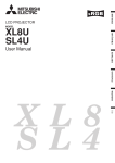
Orientation of the projector
Picture size can be set by changing the distance between the screen and the projector.
Front projection, ceiling mount
Front projection
Width
W
W
Width
W
I
Height
H
W
Center of
the lens*
H
I
Height
Center of
the lens*
L
L
L
L
The maximum projection area
The maximum projection area
* Center of the lens when the image is projected
along the top of the maximum projection area.
* Center of the lens when the image is projected
along the bottom of the maximum projection area.
For XL5950U and XL5900U only. About for XL5950LU and XL5900LU, please refer to page 30.
Distance from the screen : L
Screen
Diagonal size
Width
Height
Lens shift height
Maximum
Minimum Standard : I Movement
Distance : H
zoom (WIDE) zoom (TELE)
Lens shift
width : W
inch cm inch cm inch cm inch
inch cm inch cm inch cm
m
m
inch
36
4.6 16.6 42.0 2.5
6.2
60 152
48 122
1.8
91
89 2.3 114 2.9
48 122 120 3.0 153 3.9
2.4
6.1 22.0 55.8 3.3
8.3
80 203
64 163
100 254
80 203
60 152 150 3.8 191 4.9
3.0
7.6 27.4 69.5 4.1 10.3
90 229 227 5.8 289 7.3
150 381 120 305
4.5 11.4 40.9 103.8 6.1 15.4
6.0 15.2 54.4 138.1 8.1 20.5
200 508 160 406 120 305 304 7.7 386 9.8
250 635 200 508 150 381 381 9.7 483 12.3 7.5 19.1 67.9 172.4 10.1 25.5
300 762 240 610 180 457 458 11.6
9.0 22.9 81.4 206.6 12.1 30.6
• The above numbers are approximate, and may be slightly different from the actual measurements.
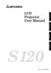
Front projection, ceiling mount
For ceiling mount, you need the ceiling mount kit.
Ask a specialist for installation. For more details,
consult your dealer.
• This warranty does not cover damage caused by
the use of any unrecommended ceiling mount kit
and the installation of the ceiling mount kit at an
improper location.
• When using the ceiling mount, set IMAGE REVERSE in the INSTALLATION menu to MIRROR INVERT. See Page 16.
• Projected images may appear darker when the
unit is used as a ceiling installation than when it
is used in the tabletop position. This does not
signify a product malfunction.
Rear projection
Ask a specialist for installation. For more details,
consult your dealer.
Screen
Caution:
• Placing the projector on a carpet reduces ventilation from the fan at the bottom and might cause
problems. Place a hard board or similar item
under the projector to facilitate ventilation of the
unit.
• Place the projector more than 50 cm (20 inch)
from the wall to prevent blocking the intake,
exhaust slots and ventilation of this projector
because hot air comes out of it.
• Do not use the projector under the following
circumstances, which may cause fire or electric
shock.
• in a dusty or humid place
• while the projector is lying sideways or upside
down
• near a heater
• in a kitchen or oily, smoky or damp place
• in direct sunlight
• with high temperature, such as a closed car
• where the temperature is lower than 41°F
(+5˚C) or higher than 104°F (40˚C).
Important:
• Do not put stress on the lens, as this may cause
damage.
• For rear projection, set IMAGE REVERSE in the
INSTALLATION menu to MIRROR. See Page 16.
EN – 9
Basic connections
This projector can be connected with various devices such as a VCR, video camera, videodisc player, and personal
computer that have analog RGB output connectors.
Important:
• Make sure that the connected device is turned off before starting connection.
• Plug in the projector and the connected devices firmly, and unplug them by holding and pulling out their
power plugs, not by pulling the power cords.
• When the projector and the connected devices are located too close to each other, the projected image may be
affected by their interference.
• See the owner’s guide of each device for details about their connections.
Projector + AV device
Important:
• Connect the video and audio plugs of the AV cable to the proper terminals matching their colors respectively.
• When the connected AV device uses a BNC connector for its video output, connect it to the VIDEO 1 (BNC)
terminal. When both the VIDEO 1 (BNC) terminal and the VIDEO 2 (RCA) terminal are engaged at the same
time, the image supplied to the VIDEO 2 (RCA) terminal takes priority.
• When the connected AV device uses a BNC connector for its S-video output, connect it to the VIDEO 2
(Y,C)(BNC) terminal. When both the VIDEO 2 (Y,C) (BNC) terminal and the S-VIDEO 2 terminal are engaged
at the same time, the image supplied to the S-VIDEO 2 terminal takes priority.
When using the video (RCA) or S-video connector When using the BNC connector
S-VCR, etc.
VCR, etc.
S-VCR, etc.
To Y output
To S-video output
To S output
To audio output
To S-video input
VCR, etc.
To audio output
To video output
To Y input
To video output
To S input
To video input
To audio input
To audio input
To video input
Projector + DVD player or HDTV decoder
Some DVD players have an output connector for 3-line fitting (Y, CB, CR). When connecting such a DVD player
with this projector, use the COMPUTER/COMPONENT VIDEO INPUT 1 terminal.
BNC-BNC cable (option)
DVD player or HDTV decoder
CB(PB)
B
B/PB
Y
G
G/Y
CR(PR)
R
R/PR
to AUDIO OUT
BNC-RCAconnector
(option)
COMPUTER AUDIO IN
AUDIO cable (option)
•
•
•
•
•
The terminals’ names Y, PB, and PR are examples of a case where a HDTV decoder is connected.
The terminals’ names are different depending on the connected devices.
Use BNC-BNC cables for connection.
The image may not be projected correctly with some DVD players.
When connecting a HDTV decoder having RGB output terminals, set the COMPUTER INPUT to RGB in the
SIGNAL menu.
EN – 10
ENGLISH
Projector + Computer
For using the COMPUTER/COMPONENT VIDEO INPUT 2 (Mini D-SUB 15P) terminals
To COMPUTER AUDIO IN
PC audio cable (option)
USB
RS-232C
REMOTE REMOTE
IN
OUT
To PC audio
output
INPUT 1
G/Y
R/PR
INPUT 2
MAIN
B/PB
AUDIO
IN
RS-232C/MOUSE
H/HV
S-VIDEO
V
VIDEO
2
Y
VIDEO
1
AUDIO
OUT
To monitor port
C
AC IN
Computer
To COMPUTER IN
(Mini D-SUB 15P)
L
AUDIO
R
AUDIO OUT
MONITOR OUTPUT
To COMPUTER OUTPUT
RGB cable for PC (option)
When outputting to both the compute's monitor and the projector.
For using the COMPUTER/COMPONENT VIDEO INPUT 1 (BNC) terminals
USB
RS-232C
REMOTE REMOTE
IN
OUT
PC audio cable (option)
computer
to COMPUTER AUDIO IN
INPUT 1
INPUT 2
MAIN
R/PR
G/Y
B/PB
AUDIO
IN
RS-232C/MOUSE
H/HV
V
S-VIDEO
VIDEO
2
Y
R/P R
VIDEO
1
AUDIO
OUT
AC IN
C
L
AUDIO
to PC audio
output
G/Y
R
B/P B
H/HV
MONITOR OUTPUT
V
AUDIO OUT
to monitor
port
Mini D-SUB 15pin-BNC
conversion cable (optional)
Important:
• When you use a longer RGB cable instead of the provided cable, the picture quality may deteriorate.
• Some computers may require additional connectors or analog RGB output adapters to be connected with this
projector. Contact your dealer for further information.
• This projector uses a stereo pin jack for its audio input. Check the type of the audio output terminal of the
connected computer and prepare a proper cable for connection. Some computers may not have the audio
output terminal.
For Macintosh
• If your Macintosh has no video port, a monitor output adapter is required. Contact your dealer for further
information.
• Some Macintoshes may require a MAC adapter for the RGB cable for connection with this projector. Contact
your dealer for further information.
About DDC™
The COMPUTER/COMPONENT VIDEO INPUT 2 terminal of this projector complies with the DDC1/2B standard.
When a computer supporting this standard is connected to this terminal, the computer will automatically load
the information from this projector and prepare for output of appropriate images.
• After connecting a computer supporting this standard to this terminal, turn on the projector’s main power
switch first, and then boot up the computer.
• You may need to install the DDC driver, depending on the computer you use. In this case, you need to download the driver from our Web site. Contact your dealer or Mitsubishi sales office for further information.
EN – 11
Preparing the projector for operation
Getting ready for projection
Adjusting the angle of projection
1. Attach the provided power cord to the projector.
2. Plug the power cord in the wall outlet.
3. Remove the lens cap.
For the best projection, project the image on a flat
screen installed at 90 degrees to the floor. If necessary, tilt the projector using the two adjustment feet
on the bottom of the projector.
Warning:
• Do not look into the lens directly when the projector is “ON.”
• The lens cap is for protecting the lens. If you leave
the lens cap on the lens with the projector turned
on, it may be deformed. Remove the lens cap when
you turn on the projector.
• The power cords for use in the U.S. and Europe
are included with this projector. Use the appropriate one for your country.
• This projector uses the power plug of three-pin
grounding type. Do not take away the grounding
pin from the power plug. If the power plug doesn’t
fit your wall outlet, ask an electrician to change
the wall outlet.
• The provided power cord for the U.S. is rated at
120 V. Never connect this cord to any outlet or
power supply using other voltages or frequencies
than rated. If you use a power supply using other
voltage than rated, prepare an appropriate power
cord separately.
• Use 100-240 V AC 50/60 Hz to prevent fire or
electric shock.
• Do not place any objects on the power cord and
keep the projector away from heat sources to
prevent damage to the power cord. If the power
cord gets damaged, contact your dealer for replacement because it may cause fire or electric
shock.
• Do not modify or alter the power cord. If the
power cord is modified or altered, it may cause fire
or electric shock.
Caution:
• Plug in the power cord firmly, and unplug it by
holding and pulling out the power plug, not by
pulling the power cord.
• Do not plug in or out the power cord with your
hand wet. It may cause electric shock.
EN – 12
screen
Adjustment foot
1. Rotate the adjustment feet for fine adjustment.
Adjustment foot
After using the projector
2. Put the adjustment feet back into the projector by
rotating the adjustment feet.
• Install the screen on a flat wall at 90 degrees to
the floor.
• Position the projector so that it projects an image
filling the screen as illustrated on page 9.
• Keep an appropriate distance from the projector to
the screen according to the screen size chart on
page 9.
• The image becomes trapezoid shape when the
screen or project is not level. Use KEYSTONE
button and + or - buttons to adjust, however, the
circumference of the image may not be focused.
Important:
• Slanting the projector more than ±15˚ (right and
left or front and rear) may cause trouble or explosion of the lamp. You can tilt the projector up to 7
degrees using the adjustment feet only.
• The image may not be projected in a shape of a
regular rectangle or with its aspect ratio of 4:3,
depending on the installation conditions of the
projector and the screen.
• When the keystone adjustment is carried out, the
adjustment value is indicated. Note that this
value doesn’t mean a projection angle.
• The allowable range of the adjustment value in
the keystone adjustment will vary depending on
the installation conditions.
To operate projector power ON
INPUT 1
R/PR
G/Y
INPUT 2
MAIN
RS-232C/MOUSE
B/PB
AUDIO
IN
2, 13
ENGLISH
USB
RS-232C
REMOTE REMOTE
IN
OUT
H/HV
S-VIDEO
V
VIDEO
2
Y
VIDEO
1
AUDIO
OUT
C
AC IN
L
AUDIO
R
TEMP LAMP POWER
AUTO POSITION
LENS SHIFT
AUTO POSITION
button
ENTER
3, 11, 12
9
5, 7
10
6, 8
3, 11, 12
COMPUTER
2
1
KEYSTONE
ZOOM/FOCUS
VIDEO
1
2
EXPAND
AUTOPOSITION
VOLUME
LASER
4
AUTO POSITION
button
MENU
KEYSTONE
ZOOM/
FOCUS
10
5, 7
VOLUME
6, 8
4
SOURCE
MUTE
MUTE button
2. Put the projector into standby mode by pressing the
main power switch. The POWER indicator lights up
red.
3. Turn the projector on by pressing the POWER button. The light source lamp starts warming up, eventually turning completely on.
• The lamp may take about a minute to light up.
• The lamp occasionally fails to light up. Try to light
up the lamp again after a few minutes.
• If the projector has not cooled down completely
since the last turning-off, the fan may start
rotating when the main power switch is turned
on and the POWER button may not function.
Press the POWER button to light up the lamp
after the fan stops.
indicator
stand-by
when light source lamp is on
light source lamp held off temporarily
R-CLICK
ENTER
P in P
STILL
16 : 9
MUTE
1. Turn on the equipment connected to the projector.
condition
MENU
LAMP POWER
green
-
red
green
red
Important:
• A darkened image may be seen right after pressing
the POWER button due to warming up of this projector. While warming up, no other commands can
be accepted.
• After the power is turned on or the LAMP MODE is
changed, the screen may flicker before the lamp operation becomes stable. This is due to the characteristics of the lamp, not a failure of the lamp.
• When the lamp indicator is blinking red, the service life of the lamp is about to end. Replace the
lamp. See pages 22 and 26.
• The picture might not be of optimum performance
in extreme hot or cold conditions. (The projector is
not malfunctioning.)
9
MUTE button
LENS SHIFT
4. Press the ZOOM/FOCUS button to FOCUS. “FOCUS” will appear on the display.
5. Adjust with the + or - button to get a fine picture.
6. Select the desired external input source by using
the COMPUTER 1,2 or VIDEO1,2 button on the remote control or the SOURCE button on the control
panel.
• Pressing the SOURCE button on the control panel
repeatedly will select VIDEO 1, VIDEO 2, COMPUTER 1 and COMPUTER 2.
• The projector automatically selects the appropriate
signal format. The selected signal format is displayed on the screen.
• The COMPUTER, VIDEO or SOURCE buttons do
not work when MENU is displayed. At this time,
the prohibition mark ( ) appears on the screen.
• When selecting the COMPUTER input, the image
may flicker. Press the $ or % button to adjust the
image.
• The intensity of the lamp will be STANDARD for 2
minutes regardless of the setting of the LAMP
MODE when the lamp turns on.
7. Press the ZOOM/FOCUS button to ZOOM. “ZOOM”
will appear on the display.
8. Adjust with the + or - button to get an approximate
size.
9.
Press the LENS SHIFT button. “LENS SHIFT”
will appear on the display.
10.Adjust with the {, }, $ or % button to get an
approximate lens position.
• If necessary, adjust focus, zoom and lens shift again.
• Focus, zoom and lens shift adjustment is possible
in the normal picture mode only. In PinP or EXPAND
mode, the adjustment is prohibited.
EN – 13
To operate projector power ON (Continue)
Turning off the projector
Use the following procedure to turn off the power.
Don’t turn off the power by switching off the main
power switch or disconnecting the power plug because these methods may cause deterioration
in the lamp’s performance or failure in the product.
11. Press the POWER button.
The message “POWER OFF? YES : PRESS AGAIN”
appears on the screen.
• To exit this mode, press any button except the POWER
button. (Some buttons on the remote control don’t
work for exit from this mode.)
12.Press the POWER button again.
The light source lamp will go out. Though the light source
lamp will go out at this second press of the POWER button, the exhaust fan continues to operate for another 120
seconds to cool down the lamp and LCD panel. In this
case, the lamp indicator will go out.
13.Turn off the main power switch, and the POWER indicator will go out.
• In cases where the main power switch is accidentally
turned off when either the intake/exhaust fan or the
power source lamp is in operation, allow the unit to
cool down for 10 minutes with the power turned off.
Repeat step 3 when turning on the power source lamp.
If the lamp does not turn on immediately, repeat this
step two or three times. Replace the lamp if it should
still fail to turn on.
AUTO POSITION button
When the image isn’t projected in the right position with
COMPUTER selected as the image source, follow the
steps below.
1. Project a bright image such as the “Trash” window on
the full screen.
2. When the screen saver is running, turn it off.
3. Press the AUTO POSITION button.
• If the image is still not in the right position, adjust the
image position using the SIGNAL menu.
Volume from the speaker
Press the volume + or – button to change the volume from
the speaker.
The volume control bar will appear on the screen.
VOLUME
15
• The volume control bar will disappear about 4 seconds
after releasing the volume buttons.
• The volume buttons don’t work while the MENU
selection bar or the MENU is being displayed.
• When a high-level audio signal, such as a DVD audio
signal, is supplied to the COMPUTER AUDIO IN
terminal, the output from the speaker may be distorted.
EN – 14
AV mute
The image and audio signals are temporarily muted by
pressing the MUTE button. To bring them back to their
normal level, press the MUTE button again.
• The audio from the AUDIO OUT jack is also muted by
pressing the MUTE button.
• If the MUTE MODE in the INSTALLATION menu is
set to LOGO, the splash screen will appear by pressing
the MUTE button.
Please contact your dealer or Mitsubishi sales office for
further information.
• You can alter the splash screen freely. Please contact
your dealer or Mitsubishi sales office for further
information.
• The lamp mode becomes “LOW” during muting.
Therefore, the display of LOGO will darken, which
isn’t a failure.
• Muting will be cancelled in 3 hours automatically for
the purpose of protecting devices. However, when the
mute mode has been set to “LOGO,” muting won’t be
cancelled.
ANAMORPHIC mode
When playing DVD discs containing data of letterboxed
image, press the 16:9 button. Exit the ANAMORPHIC
mode, by pressing the 16:9 button again.
Caution:
• When you have finished using this projector, wait 120
seconds for the exhaust fans to stop. Then turn off the
main switch and unplug the power cord from the wall
outlet, for safety purposes.
• The lamp cannot be turned on again for 60 seconds after
it was turned off for precautionary purposes. It will take
another 60 seconds before the lamp indicator goes off. If
you want to turn on the projector again, wait until the
indicator is off, and then press the POWER button.
• The exhaust fan rotates faster as the temperature around
the projector rises.
• When the temperature around the projector rises too
high, the sign “TEMPERATURE!!” blinks red on the
screen. If the temperature stays too high, the lamp will
be go out automatically.
Menu operation
CONTRAST
BRIGHTNESS
sRGB
COLOR MATRIX *1
COLOR TEMP. *1
COLOR
*2
TINT
SHARPNESS
GAMMA MODE
INSTALLATION
AUTO POWER ON
AUTO POWER OFF
SPLASH SCREEN
BACK COLOR
MUTE MODE
LAMP MODE
IMAGE REVERSE
LENS SHIFT
RED
± 30
± 30
YELLOW
± 30
± 30
GREEN
± 30
ON , OFF
CYAN
± 30
VIDEO
BLUE
± 30
COMPUTER
MAGENTA
± 30
USER
SATURATION
±5
OFF
RGB-TINT
± 15
STANDARD
CONTRAST R
± 30
HIGH
CONTRAST B
± 30
LOW
BRIGHTNESS R
± 30
USER
BRIGHTNESS B
± 30
± 10
(Displays only when the source is selected to VIDEO)
± 10
(Displays only when the source is selected to VIDEO)
± 10
AUTO, DYNAMIC, STANDARD, THEATER
ON , OFF
OFF, 5, 10, 15, 30, 60 min
ON , OFF
BLUE, LOGO, BLACK
BLACK, LOGO
STANDARD, LOW
OFF, MIRROR, INVERT, MIRROR INVERT
USER
LOCK
RESET
MENU POSITION
EXPAND MODE
FRAME POSI.
VIDEO SIGNAL
SCART INPUT *3
ANAMORPHIC
3D CineView *4
LANGUAGE
RESET ALL
1 (Upper left), 2(Lower right)
(The item can not be selected when
the source is selected to COMPUTER)
1-4
1-5
AUTO , NTSC , PAL , SECAM , 4.43NTSC , PAL-M , PAL-N , PAL-60
ON , OFF
OFF, CENTER, UPPER, LOWER
ON , OFF
, English, Español, Deutsch, Français, Italiano,
,
,
,
OK
SIGNAL
MEMORY CALL
HORIZ.POSITION
VERT.POSITION
FINE SYNC. *3
TRACKING *3
COMPUTER INPUT *3
*3
HOLD
AUTO, USER1, USER2
0 - 999
*5
0 - 999
*5
0 - 39
0 - 9999
*5
RGB, YCBCR / YPBPR
AUTO
ON
OFF
USER
USER1, USER2
USER1, USER2
* 1: The item can not be selected when the sRGB is set to ON.
* 2: The item can not be selected with certain signals.
* 3: The item can not be selected when the selected source
is VIDEO or S-VIDEO.
* 4: The item can be selected only when the selected source
is VIDEO or S-VIDEO or the inputted signal is TV50 or TV60.
* 5: Setting range is different with certain signals.
Basic operation
Several settings can be adjusted using Menu.
EXAMPLE: Auto power off time setting
1. Press the MENU button.
opt.
XGA60
IMAGE
2. Press the $ or % button to select the INSTALLATION menu.
opt.
XGA60
INSTALLATION
3. Press the ENTER button (or } button).
opt.
XGA60
INSTALLATION
AUTO POWER
ON
AUTO POWER
OFF
ON
SPLASH SCREEN
BACK COLOR
ON, OFF
OK
FEATURE
MEMORIZE
DELETE
DEFAULT
OFF
OFF
ENGLISH
IMAGE
BEGIN
END
CLAMP POSITION *3
CLAMP WIDTH *3
HORIZ. PIXELS *3
VERT LINES *3
VERT. SYNC.
SHUTTER(U)
SHUTTER(L)
SHUTTER(LS)
SHUTTER(RS)
-1 - -99
1 - 99
0 - +63
*5
1 - 63
*5
0 - 9999
*5
0 - 9999
*5
AUTO, ON, OFF
0 - 383
0 - 383
0 - 510
0 - 510
4. Press the { or } button to select AUTO POWER
OFF.
AUTO POWER
ON
AUTO POWER
OFF
OFF
OFF
5. Press the $ or % button to adjust auto power off
time.
AUTO POWER
ON
AUTO POWER
OFF
OFF
30 min
6. Exit the menu system by pressing the MENU button several times.
• If the menu operation is not working, press the
RESET button on the terminal board using a suitable sharp object, push gently.
• The settings with
mark, you should press the
ENTER button after selecting.
ON
BLUE
EN – 15
Menu operation (continued)
1 IMAGE
CONTRAST ......... Adjusts the picture contrast. The contrast becomes higher as the
opt.
XGA60
number increases.
BRIGHTNESS ..... Adjusts the image brightness. The image becomes brighter as IMAGE
the number increases.
CONTRAST
0
sRGB .................... Select ON to display an image emphasizing on the color
BRIGHTNESS
0
reproducibility.
OFF
sRGB
• When sRGB is ON, COLOR MATRIX, COLOR TEMP. and
COMPUTER
COLOR MATRIX
GAMMA COLLECTION can’t be ad justed.
STANDARD
COLOR
TEMP.
COLOR MATRIX ......... Adjusts the color balance in each color of the image. See page 18.
COLOR TEMP. .... Adjusts the color temperature. See page 19.
COLOR
0
COLOR ................ Adjusts the color intensity of the image. (Available only when
TINT
0
VIDEO is selected as the source.)
SHARPNESS
0
TINT .................... Adjusts the color balance of the image. The color balance of the
GAMMA MODE
AUTO
image shifts green as the number increases and shifts to purple
as the number decreases. (Available only when VIDEO is
selected as the source.)
• When the TV50 (PAL, SECAM) signal is inputted, TINT can’t be adjusted.
SHARPNESS ....... Adjusts the image sharpness. The image sharpness rises as the number increases.
GAMMA MODE ... When AUTO is selected, the appropriate gamma mode is automatically selected depending on the
input signal. For normal use, select AUTO. Select DYNAMIC for computer sources. Select
STANDARD for sport scenes and video sources. Select THEATER for projecting film sources.
2 INSTALLATION
opt.
XGA60
AUTO POWER ON ...... Select ON to boot up the projector automatically by turning on
an externally connected power switch such as a breaker even INSTALLATION
when the main power switch of the projector is off. Use this
AUTO POWER
OFF
ON
setting when the projector is hanging from the ceiling.
AUTO POWER
OFF
OFF
• The projector will be in the stand-by mode when the lamp
ON
SPLASH SCREEN
is off. Use the remote control to turn on the lamp.
BACK COLOR
BLUE
AUTO POWER OFF .... Set the time elapsed before the projector enters into the stand-by
mode when there is no signal inputted from the selected source.
BLACK
MUTE MODE
SPLASH SCREEN ....... Select ON to display the splash screen when the power is turned
STANDARD
LAMP MODE
ON.
OFF
IMAGE REVERSE
• The splash screen can be changed. For more details, please
USER
LENS SHIFT
consult your dealer.
BACK COLOR ...... Use to select the background, BLUE, BLACK or LOGO, which
will be displayed when there is no signal inputted from the selected source. When the LOGO is
selected, the splash screen will be displayed.
MUTE MODE ...... Use to select the background, BLACK or LOGO, which will be displayed when the MUTE button is
pressed. When the LOGO is selected, the splash screen will be displayed.
LAMP MODE ....... Use to change the brightness of the lamp. When LOW is selected, the image will become darker,
though the power will be saved, operating sound will be reduced.
• The intensity of the lamp will be STANDARD for 2 minutes regardless of the setting of the LAMP
MODE when the lamp turns on.
• When the LAMP MODE is changed, the screen may flicker. This is not a failure of the lamp.
IMAGE REVERSE ...... Use to reverse or invert the projected image. Select MIRROR in rear projection. Select MIRROR,
INVERT in rear projection with the projector hanging from the ceiling.
LENS SHIFT ........ To enter the LENS SHIFT setting mode, press the ENTER button. For lock the lens position, set
LOCK to ON. For reset the lens position, select RESET and press the ENTER button.
ON
• When no signal is supplied for 6 hours with BACK COLOR set to BLACK, it changes to BLUE
automatically for the purpose of protecting the projector.
• When you continue projection for a long time with BACK COLOR or MUTE set to LOGO, an after-image
may persist on the screen.
• When the signal is lost during muting with MUTE set to LOGO, AUTO POWER OFF is ignored even
though it is active.
EN – 16
A
A
A
• When SCART is set to ON, nothing is output to the external monitor.
• When SCART is set to ON, normal computer signals are not projected.
• Use SCART-BNC (or SCART-Mini D-SUB 15P) cable (option), when connecting with AV device equipped with
the SCART terminal.
• Some AV devices equipped with the SCART terminal may not be compatible with the projector.
• When VIDEO SIGNAL is set to AUTO, the image may not be projected with correct colors. Change the setting of
VIDEO SIGNAL depending on the input signal in such cases.
• When 3D Cine View is switched from OFF to ON, you can check the motion detection operation about three seconds.
The buttons on the remote control don’t work during this period, which isn’t a failure.
• When the LANGUAGE in FEATURE menu is set to English and NTSC video format is selected, the brightness is
decreased 15 points by set-up cancel function for U.S. (The indicated value is not changed.) The image becomes darker,
but this is not a failure of the projector.
4 SIGNAL
MEMORY CALL .......... Use to select AUTO, USER 1 or USER 2. See page 18.
HORIZ. POSITION ...... Use to adjust the horizontal position of the image.
VERT. POSITION ........ Use to adjust the vertical position of the image.
FINE SYNC. ......... Use to synchronize the projector with PC input signals so that
the image is not blurred.
TRACKING .......... Use to avoid image noise such as wide stripes.
COMPUTER INPUT ...... The unit adjusts itself automatically when connected to a DVD
player with a component video output (Y, CB, CR). In the case the
projector is connected to equipment that includes RGB output
terminal, adjust to RGB mode.
HOLD .................. Adjusts the image when flagging occurs near the top of the
screen.
opt.
XGA60
SIGNAL
A
U
MEMORY CALL
AUTO
HORIZ. POSITION
0
VERT. POSITION
0
FINE SYNC.
0
TRACKING
R
RG
GB
B
0
COMPUTER INPUT
RGB
HOLD
USER
MEMORIZE
5 SIGNAL - USER (Normally, there is no need for adjustments.)
SIGNAL-USER
CLAMP POSITION/
CLAMP WIDTH .......... If you use something similar, the brighter colors of the projected CLAMP POSITION
image may become blurred. In this case, adjust CLAMP POSITION CLAMP WIDTH
or CLAMP WIDTH.
HORIZ. PIXELS
HORIZ.PIXELS .... Use to adjust the width of the image. The image size grows wider as
the number increases. (Adjust to the horizontal pixels of the input VERT. LINES
VERT. SYNC.
signal for normal setting.)
VERT.LINES ....... Use to adjust the height of the image. The image size grows higher SHUTTER(U)
as the number increases. (Adjust to the vertical lines of the input SHUTTER(L)
signal for normal setting.)
SHUTTER(LS)
VERT.SYNC. ........ Use to adjust the image when its motion does not run smoothly.
SHUTTER(RS)
Select AUTO for normal setting.
SHUTTER(U) ....... Use to adjust the image when the noise etc. appears on top part of
image.
SHUTTER(L) ....... Use to adjust the image when the noise etc. appears on bottom part of image.
SHUTTER(LS) ..... Use to adjust the image when the noise etc. appears on left side of image.
SHUTTER(RS) ..... Use to adjust the image when the noise etc. appears on right side of image.
AUTO
DELETE
DEFAULT
0
0
0
0
AUTO
0
0
0
0
• When the setting of the SIGNAL-USER menu is changed, the image may not be displayed correctly. In this case, select
DEFAULT in the SIGNAL menu, and press the ENTER button.
EN – 17
ENGLISH
3 FEATURE
opt.
XGA60
MENU POSITION ....... Use to select the position of the menu on the screen,
(upper
(lower right).
left) or
FEATURE
EXPAND MODE .. Select the mode for enlarging screen. See page 20.
MENU POSITION
1.
FRAME POSI. ...... Sets the position of sub screen. See page 20.
A EXPAND MODE
1.
VIDEO SIGNAL ... When AUTO is selected, the appropriate video format is
FRAME POSI.
3.
automatically selected depending on the input signal. If the
AUTO
image isn’t displayed correctly, select the desired video format ? VIDEO SIGNAL
manually.
SCART INPUT
OFF
SCART ................. Select ON when connecting with a device equipped with the
ANAMORPHIC
OFF
SCART terminal that can output RGB signal. SCART terminal
3D CineView
ON
is used mainly in Europe. Select OFF normally.
AË
English
LANGUAGE
ANAMORPHIC .... Select the desired position, UPPER, CENTER or LOWER when
OK
RESET ALL
playing DVD discs containing data of letterboxed images.
3D Cine View ........ Select ON for high quality video image. Select ON normally.
LANGUAGE ........ Use to select the language used in the menus. (
/ English / Español / Deutsch / Français / Italiano
/
/
/
/
)
RESET ALL ......... Use to reset the MENU settings (except LANGUAGE).
Picture adjustment
User memory for signal setting
This projector can memorize the maximum of 2 signal
menu settings.
Memorizing the setting
1. Select MEMORIZE in the SIGNAL menu, and press
the ENTER button.
2. Press the $ or % button to select the memory which you
wish to record (USER 1 or USER 2).
3. Press the ENTER button.
• Any buttons are ineffective about 3 seconds of
recording setting. Wait for recording to have been
completed before operating the buttons.
Select the user setting
Select MEMORY CALL in SIGNAL menu, and press the
$ or % button to select the memory (USER 1 or USER 2).
Reset the recorded setting
1. Select DELETE in the SIGNAL menu, and press the
ENTER button.
2. Press the $ or % button to select the memory which you
wish to reset (USER 1 or USER 2).
3. Press the ENTER button.
The recorded setting will be reset.
• Any buttons are ineffective about 3 seconds of
resetting the recorded setting. Wait for resetting to
have been completed before operating the buttons.
sRGB
0
COLOR TEMP.
STANDARD
COLOR
0
TINT
0
0
AUTO
To control the level of white-to-black in the image :
Adjust CONTRAST in IMAGE menu. Press the %
button to increase the contrast and the $ button to
reduce it.
To control the light level of the image :
Adjust BRIGHTNESS in IMAGE menu. Press the %
button to lighten the image and the $ button to
darken the image.
To determine the intensity of the color :
Adjust COLOR in IMAGE menu. Press the %
button to increase the amount of color in the image
and the $ button to decrease it.
To adjust the red-green color balance of the image :
Adjust TINT in IMAGE menu. Press the % button
to increase the amount of green in the image and the
$ button to increase the amount of red in the image.
To adjust the detail and clarity of the image :
Adjust SHARPNESS in IMAGE menu. Press the %
button to make the picture seem sharper and the $
button to make it softer.
EN – 18
3. Press the ENTER button.
COLOR MATRIX
RED
0
YELLOW
0
GREEN
0
CYAN
0
BLUE
0
MAGENTA
0
SATURATION
0
RGB-TINT
0
6. Repeat steps 4 and 5 for more adjustments.
OFF
COMPUTER
GAMMA MODE
.
5. Press the $ or % button to adjust the color balance
of the color.
COLOR MATRIX
SHARPNESS
2. Press the $ or % button to select USER
0
IMAGE
BRIGHTNESS
1. Select COLOR MATRIX in IMAGE menu.
XGA60
You can adjust the picture by using the IMAGE menu.
CONTRAST
This feature adjusts the color balance in each color of
RGB (Red, Green, Blue), and their neutral colors
(yellow, cyan, magenta) by using Color correction
adjustment. Use Color correct adjustment when
enphasizing a specific color, or when only a certain
color balance is not correctly adjusted.
4. Press the { or } button to select the desired color.
• If you wish to adjust the color intensity of the
image, select SATURATION.
• If you wish to adjust the all color balance of the
image, select RGB-TINT.
Adjusting the image
opt.
Color matrix
7. Exit the menu system by pressing the MENU button several times.
• When using the setting which has been already
prepared, select desired position VIDEO or
COMPUTER in step 2. When the source is selected
to VIDEO or S-VIDEO, VIDEO will be selected
automatically. When the source is selected to
COMPUTER, COMPUTER will be selected
automatically.
• When not using Color matrix adjustment, select
OFF in step 2.
1. Select COLOR TEMP in IMAGE menu.
2. Press the $ or % button to select USER
.
3. Press the ENTER button.
COLOR TEMP.-USER
CONTRAST R
0
CONTRAST B
0
BRIGHTNESS R
0
BRIGHTNESS B
0
4. Press the { or } button to select the desired item.
5. Press the $ or % button to adjust the item.
6. Repeat steps 4 and 5 for more adjustments.
7. Exit the menu system by pressing the MENU button several times.
About color temperature
There are different kinds of white color. Color temperature is
a way to show the differences. The white, which temperature
is low, becomes reddish white. When the color temperature is
higher, the white becomes more bluish. This projector sets
this color temperature by changing the numbers of contrast
blue and red.
To set the color temperature high:
Set the contrast B (Blue) number high, and the contrast R
(Red) number low.
To set the color temperature low:
Set the contrast B (Blue) number low, and the contrast R
(Red) number high.
Adjustment from personal computer
Although this projector sets proper signal systems
automatically for the image signal from personal
computers, it cannot be applied to some of personal
computers. In this case, press the AUTO POSITION
button. If the images are still not projected correctly,
use the MENU display to adjust the projected images.
ENGLISH
Image flickers / Image is out of focus :
Adjust FINE SYNC. in SIGNAL menu.
Color temperature
SIGNAL-USER
CLAMP POSITION
0
CLAMP WIDTH
0
HORIZ. PIXELS
0
VERT. LINES
0
VERT. SYNC.
AUTO
SHUTTER(U)
0
SHUTTER(L)
0
SHUTTER(LS)
0
SHUTTER(RS)
0
Wide strips appear :
Adjust CLAMP POSITION or CLAMP WIDTH of
each menu in SIGNAL - USER menu.
Noise appears on right or left side of image :
Adjust SHUTTER (LS), SHUTTER (RS) or HORIZ.
PIXELS of the menu in SIGNAL - USER menu.
Noise appears on top or bottom part of image :
Adjust SHUTTER (U), SHUTTER (L) or VERT.
LINES of the menu in SIGNAL - USER menu.
Top part of image curves :
Change the setting of HOLD in SIGNAL menu.
Select ON , press the ENTER button and adjust
BEGIN or END for image which top part is the least
curved.
Image does not move naturally :
Adjust VERT. SYNC. of the menu in SIGNAL USER menu. Select AUTO for normal setting.
curved. Select AUTO for normal setting.
• Do not change each menu setting in USER menu
for normal setting.
Simple adjustment method
1. Select HORIZ. POSITION in SIGNAL menu.
2. Press the$ or % button to adjust the horizontal
start position (the left side of image).
3. Select TRACKING in SIGNAL menu.
opt.
XGA60
SIGNAL
A
U
MEMORY CALL
AUTO
5. Repeat steps 1 to 4 for fine adjustment.
HORIZ. POSITION
0
6. Select VERT. POSITION in SIGNAL menu.
VERT. POSITION
0
FINE SYNC.
0
7. Press the$ or % button to adjust the vertical
start position (the top end of image).
TRACKING
R
RG
GB
B
4. Press the$ or % button to adjust the horizontal
end position (the right side of image).
0
COMPUTER INPUT
RGB
HOLD
USER
MEMORIZE
AUTO
DELETE
DEFAULT
Image moved to right or left :
Adjust HORIZ. POSITION in SIGNAL menu. Press
the % button to move the image to left. Press the $
button to move the image to right.
Image moved to up or down :
Adjust VERT. POSITION in SIGNAL menu. Press
the % button to move the image to upward. Press
the $ button to move the image to down.
EN – 19
Advanced features for presentation
Setting the Expand mode
1. Press the MENU button.
REAL screen display
• During REAL mode, Press the $ or % buttons
for fine adjustment.
• During REAL mode, the { and } buttons are
not working. At this time, the prohibition mark
( ) appeares on the screen.
• The expanding rate cannot be changed by pressing either the + or - button.
2. Press the $ or % to select the FEATURE menu.
Picture in Picture (PinP)
Expand
By pressing the EXPAND button on the remote control, you can magnify the detailed image of the picture.
You can also view the screen displaying the picture as
its original size (native resolution display).
3. Press the ENTER button.
4. Press the { or } button to select EXPAND MODE
or FRAME POSI.
5. Press the $ or % to set the EXPAND MODE or
FRAME POSI.
6. Press the MENU button twice to exit the menu system.
EXPAND MODE
(EXPAND MODE 1) (EXPAND MODE 2) (EXPAND MODE 3) (EXPAND MODE 4)
Normal
image
Zooming Zooming
image
image
Normal
image
Zooming
image
Native resolution
display
FRAME POSI.
(FRAME POSI.
1~4)
1
2
4
3
(FRAME POSI. 5)
One of the special features of this unit is the picturein-picture (PinP) mode. PinP allows you to view different sources at the same time.
Using the PinP mode
1. Press the PinP button on the remote control.
• When the image from VIDEO IN or S-VIDEO
IN terminal is displayed on the screen, the image from COMPUTER IN terminal is displayed
as sub-image.
• When the image from COMPUTER IN terminal
is displayed on the screen, the image from VIDEO
IN or S-VIDEO IN terminal is displayed as subimage.
2. If necessary, select the desired external input source
of the image by using the VIDEO or COMPUTER
button.
To switch Main image and Sub image
3. Press the { or } buttons on the remote control.
To change frame position
4. Press the $ or % buttons on the remote control.
Main
image
Sub
image
Using the Expand mode
1. Press the EXPAND button.
• You can magnify different areas of the active picture by pressing the {, }, $, % button.
• You can change the magnification of the zoomed area
by pressing the + or - button.
2. Press the EXPAND button twice on the remote control.
The normal screen display will appear on the screen.
• Display enlargement does not work with
video input or S-video input.
• In EXPAND mode, you cannot adjust the zoom/focus and the volume.
• The Expand mode may not function depending on
the input signal. For more details, refer to page
29.
FRAME POSI.
(FRAME POSI.
1~4)
1
2
4
3
(FRAME POSI. 5)
Main
image
Sub
image
5. Press the PinP button on the remote control.
The sub image will be disappear.
• Adjusting contrast, brightness, tint or color is not
available in PinP mode.
• In PinP mode, both Main image and Sub image
are displayed with their frames skipped.
• In PinP mode, the audio of the Main image is
outputted.
• In PinP mode, the images may not move smoothly.
• The PinP mode may not function depending on the
input signal. For more details, refer to page 29.
• The UXGA signal isn’t displayed as a sub image.
Still
How to stop the picture temporarily (still picture).
1. Press the STILL button on the remote control.
The picture will freeze temporarily.
To resume picture activity.
2. Press the STILL button on the remote control again.
EN – 20
By connecting to personal computer through the USB or SERIAL port, you can operate your computer with the
projector remote control.
Projector + computer with USB connector
to USB port
to USB
USB
RS-232C
REMOTE REMOTE
IN
OUT
INPUT 1
R/PR
INPUT 2
MAIN
G/Y
USB cable
(option)
RS-232C/MOUSE
B/PB
H/HV
AUDIO
IN
V
VIDEO
2
S-VIDEO
Y
USB 4P
(type B)
USB 4P
(type A)
VIDEO
1
AUDIO
OUT
C
AC IN
L
AUDIO
R
• You can use the mouse remote control function with a computer supporting USB only.
• When the lamp is turned ON, the computer connected with the USB cable may not work correctly. In this
case, restart the projector and the computer. If possible, you should disconnect the USB cable when the lamp
is turned ON.
Projector + computer with SERIAL port
to RS-232C/MOUSE
terminal
RS-232C cable
USB
RS-232C
REMOTE REMOTE
IN
OUT
INPUT 1
R/PR
RS-232C/MOUSE
B/PB
H/HV
V
to SERIAL port
INPUT 2
MAIN
G/Y
AUDIO
IN
VIDEO
2
S-VIDEO
8P
D-SUB 9P
Y
VIDEO
1
AUDIO
OUT
AC IN
C
L
AUDIO
R
• Turn off computer and the projector before connecting with SERIAL port. When connecting the computer with
the projector when the personal computer is on, the remote control does not work as a mouse. In that case,
restart the personal computer.
• When the projector is connected with USB terminal and RS-232C terminal at the same time, only the terminal which the projector recognizes first will work.
• When you use the RS-232C cable together with an extension cable, the function may not work correctly.
Operation
COMPUTER
2
1
KEYSTONE
ZOOM/FOCUS
VIDEO
1
2
EXPAND
AUTOPOSITION
VOLUME
LASER
left click
This operates in the same
way as the left button on
the computer mouse.
mouse pointer
Use to move the cursor on the image,
instead of the computer mouse.
MENU
R-CLICK
ENTER
P in P
STILL
16 : 9
MUTE
R-CLICK
This operates in the same way as the right
button on the computer mouse.
LENS SHIFT
EN – 21
ENGLISH
Mouse remote control
Lamp replacement
The lamp is designed to project the image on the
LCD panels. When the lamp no longer functions,
replace it with a new one.
Caution:
• Do not remove the lamp immediately after using
the projector, you may get burned because of the
high temperature of the lamp.
• When you replace the lamp, press the power
button to power off, then wait for 120 seconds in
stand-by mode to allow the lamp and LCD panels
to cool. Turn off the main switch, unplug the
power cord from the outlet, and wait one hour so
that the lamp is cooled to the touch.
• Do not remove the lamp except for replacement.
Careless treatment can cause injury or fire.
• Do not touch the lamp element directly. It may
break and cause you to injure or burn yourself.
• Be sure not to drop the lamp lid screw into the
projector. Also be sure not to insert metal or any
flammable objects, it may cause fire or electric
shock. If any objects are inserted, please unplug
and contact your dealer.
• Install the lamp securely, failure may cause a fire.
• If the light bulb part breaks, some small glass
fragments may fall out through the small cooling
grill, and sticks to the inside of projector or the
lamp box. When taking the lamp out, make sure
to turn over the projector and hold the handle of
the lamp box to avoid injury from the glass fragments.
• Never shake the lamp or hold
it in front of your face after
removing the lamp box. The
glass fragments may fall out
and cause injuries to your
eyes and so on.
1. Reverse the projector gently.
2. Loosen the screws of the
lamp lid (a) using a Phillips
screwdriver (+), and remove
the lid.
• Remove the lamp cover in
the direction of the arrow as
indicated.
3. Loosen screws (b) using a
Phillips screwdriver (+), and
remove them.
4. Pull up the handle.
5. Hold onto the projector
by the handle as you
pull out the lamp.
• Pull the lamp out of the
projector slowly. Should
the light bulb be broken,
glass fragments will spill
out if the lamp is pulled
out too quickly.
• Once the lamp has
been removed, do not
spill liquid on it, place it
near flammable objects or
where children can touch
it. Otherwise, it will cause
injury or fire.
6. Insert the new lamp
securely into the projector
body in the right direction.
EN – 22
(a)
(b)
7. Put the handle back to
the holding point.
(b)
• Make sure that the
handle is locked.
8. Tighten up the screws
(b) using a Phillips
screwdriver (+).
9. Tighten up the screws
of the lamp lid using a Phillips screwdriver (+).
How to reset the operation time meter
Plug in the power cord, switch on the projector, and
reset lamp time by pressing the $, % and POWER
buttons on the contro panel simultaneously.
Important:
• If the 3 buttons was not pressed at the same time,
the lamp time may not be reset.
• Please confirm the TEMP indicator illuminates
about 2 seconds and the lamp time has been
reset.
• The projector will not turn on if you do not secure
the lamp lid.
• You must reset the operation time meter after you
replace the lamp.
• Do not reset the operation time meter unless the
lamp has been replaced.
Caution:
• Do not spill liquid on the lamp or place it near
flammable objects or where children can touch it.
Otherwise, it could cause injury or fire.
• Be sure that the projector guide is firmly inserted
between the right and left lamp guides.
Interval of the lamp replacement
The interval of the lamp replacement about 1,500 hours of
consecutive use. Replacement span may differ according
to operating environment, and may be shorter than 1,500
hours. Decreases in luminescence and/or color brightness
will indicate that the light source lamp needs to be replaced. When lamp operation time exceeds 1,000 hours*1,
the indicator will flash alternately between green and red
(while the lamp is in operation; when the lamp is not in
operation, the indicator will appear red only) and the
lamp replacement message will appear on the screen for
one minute everytime the power is turned on. When the
lamp has been used for about 1,400 hours*1, the replacement message (LAMP:>1400H) will appear on the screen
for one minute everytime 10 hours after. When the lamp
has been used for about 1,500 hours*1,*2, the projector will
automatically shut off for safety and the power indicator
light will be red. The projector cannot be used until the
lamp has been replaced and operation timer has been
reset.
Caution:
• The lamp is fragile. If broken, be careful not to cut
yourself with glass fragments.
• The replacement span of the lamp depends on the
environment. For replacement lamps, please contact
your dealer.
The projector automatically shuts off when the
lamp is used up in about 1,500 hours*1,*2 and cannot
be used until the lamp is replaced and the internal
timer is reset.
*1) When LAMP MODE of the INSTALLATION menu
is set to STANDARD.
*2) When LAMP MODE is set to LOW, the duration
will be extended maximum up to 2,000 hours.
Caution:
Be sure to turn off the projector and unplug the
power cord from the wall outlet before you perform
any maintenance on the projector.
Cleaning the air-filter
Clean the air-filter frequently (about once a month).
If the filter or ventilation slots become clogged with
dirt or dust, the temperature inside of the projector
may rise and cause some troubles, such as damage of
inside parts, and shortening the life of panel.
• When the temperature inside of the projector
rises, the TEMP indicator blinks in red, and the
power will be shut off to be stand-by which LAMP
indicator is turned off.
1. To remove the filter
cover, slide the cover
in the direction of the
arrow.
2. Remove the airfilter from the filter
cover.
3. Wash the air-filter or
change to the new filter.
• Use water or a mild
detergent diluted with
water to clean the filter.
Rinse the filter thoroughly and let it dry
completely.
Cleaning the projector and the
ventilation slots
Use a soft cloth to clean the projector and the ventilation slots. When the slots become dirty, wipe them
with a soft cloth dampened with a diluted mild
detergent, and then wipe them with a dry cloth.
• Clean the inside of the terminal cover frequently
as dust is apt to be collected.
To protect the surface of the projector from fading or
deteriorating:
• Do not spray insecticide on or inside the
projector.
• Do not use benzine or thinner to clean it.
• Do not let rubber or plastic materials come into
contact with the projector.
Cleaning the lens
Use a standard lens-cleaning brush or a piece of lens
tissue dampened with lens cleaning fluid. The lens
surface is fragile. Use only recommended, nonabrasive lens-cleaning materials. Do not touch the lens
with your fingers.
Filter cover
Filter
4. Attach the air-filter to the filter cover.
5. Attach the filter cover to the projector.
• Make sure that the air-filter is attached correctly without displacement.
Important:
• If the filter is damaged or becomes extremely
dirty, change to the provided new filter. If you
wish to another new filter, contact your dealer for
replacement.
• The power will not turn on if the air-filter cover is
improperly installed.
Caution:
Be sure to use the projector with an air-filter. If not,
dust may get inside the projector, causing a fire or a
breakdown.
EN – 23
ENGLISH
Maintenance
About the terminal cover (with Anti-Theft Alarm device)
This projector includes a terminal cover with AntiTheft Alarm device. Once the terminal cover is
installed, its Anti-Theft Alarm device will detect
vibration caused by the projector being moved and
emit an alarm.
• Mitsubishi assumes no responsibility or liability
for theft or other damages.
Procedure for setting the Anti-Theft
Alarm device
Insert dry cell batteries into the theft warning
device
1. Open the battery cover of the theft warning
device.
2. Check the (+) and (-) ends of the battery, and
insert it from the (-) end first.
Battery cover
Power switch
ON
3. Tighten the three screws that keep the terminal
cover in place.
4. Install the projector in a specified location.
5. Press the battery level check button until you
hear a buzzer sound.
6. Remove the safety pin.
The Anti-Theft Alarm device is now in standby.
• This package includes a sticker which shows that
the Anti-Theft Alarm device is active. Visible
placement of this sticker is recommended.
• To temporarily halt the Anti-Theft Alarm device,
insert the safety pin.
• Vibrations will not cause the alarm to sound for
several seconds after the power switch is turned
ON.
• Vibrations will not cause the alarm to sound for
several seconds after the safety pin is removed.
• Vibrations and shocks from earthquakes may
cause the alarm to sound. In such situations,
insert the safety pin to halt the alarm.
• Batteries may come loose during transportation.
Please remove them beforehand.
Procedure for changing batteries
• Inserting the battery from the (+) end makes it
difficult to fit the (-) end into the coil spring.
Forcing in the battery in such a position may
shred the outside label, causing a short circuit
and overheating.
• Please refer to page 8 for information on how to
handle dry cell batteries.
3. Close the battery cover.
How to check battery level
Use a pointed object to push the battery level check
button.
safety pin hole
battery level check button.
safety pin
Screws
4. Insert the included safety pin into the safety pin
hole.
• If the safety pin is not inserted, the vibrations
and shocks of normal use may cause the alarm to
sound.
5. Turn the power switch ON.
Install the terminal cover
1. Insert the four tabs on the terminal cover into the
holes on the projector’s side.
2. Slide the terminal cover toward the back of the
projector.
Tabs
EN – 24
• A buzzer will sound while the button is being
pushed. If there is no buzzer sound, then batteries
need to be changed.
• Sounding the buzzer for a long time will consume
battery power.
Change the dry cell batteries
1. Insert the safety pin into the safety pin hole.
2. Loosen the three screws that keep the terminal
cover in place.
3. Slide the terminal cover toward the front of the
projector.
4. Pull the terminal cover toward you and remove it.
• Attention must be paid when removing the
terminal cover as there could be foreign objects
inside.
• Removal of dust found inside the terminal cover is
recommended when changing batteries.
5. Open the battery cover and remove the old dry cell
batteries.
6. Check the (+) and (-) ends of the new battery, and
insert it from the (-) end first.
• Use alkaline AA batteries.
• Standard battery life is approx. six months (when
using alkaline dry cell batteries). Please check the
battery level and change batteries regularly.
7. Close the battery cover.
The following offers solutions to some of the common problems you may encounter. We suggest that you consult
this chart before contacting your dealer.
PROBLEMS
The power is off.
No picture appears
on the screen.
CAUSE
POSSIBLE SOLUTIONS
• The air inlet slots, outlet slots or air filter is clogged
with dust or some objects.
POWER indicator does not light up.
• Power cord is unplugged from the outlet.
• Power cord is disconnected from the projector.
• The main switch is turned off.
• The lamp lid is open.
POWER indicator blinks red.
• The projector has been turned on again too soon after
having been turned off.
• When the power switch was turned off while the fan
was running, during or after lamp operation.
• The room temperature is too high.
(Does the LAMP indicator show an unusual condition?)
• Lamp is no longer working.
POWER indicator blinks between red and green.
• The filter cover is not closed.
• When the LAMP indicator or the TEMP indicator is
either on or blinking, the main unit requires repairs.
• Remove the object.
• Lens is covered by lens cap.
• When the LAMP indicator or the TEMP indicator is
either on or blinking, the main unit requires repairs.
• The equipment connected to this projector is not turned on.
• Hookup is not made correctly with other equipment.
• The input source is not selected correctly.
• Take the lens cap off.
• See page 26.
• An extension cord is being used instead of the supplied
cable.
•
•
•
•
Plug the power cord into the outlet.
Insert the power cord into the projector.
Turn the main switch on.
Close the lamp lid.
• Wait for the lighting sequence.
• Turn the power switch on and off several times.
• Refer to "Indicators" on page 26.
• Replace the lamp with a new one.
• Close the cover correctly.
• Contact your dealer.
• Turn on the connected equipment.
• Confirm the hookup.
• Select the correct source according to the equipment
connected to this projector.
• Check whether the image is displayed correctly by
replaceing it with the supplied cable. When the image
is displayed correctly, use the extension cord along with
an RGB signal amplifier.
The image is
turned off.
• The air inlet slots, outlet slots or air filter is clogged
with dust or some objects.
(In this case, the TEMP indicator does not light up.)
• Remove the object and turn off the main power switch.
After about 10 minutes, Turn the projector on.
The image is
distorted.
• The projector is not at a right angle to the screen.
• Adjust the angle of the projector to make a right angle
to the screen. See page 12.
The image is dark.
• Brightness, tint and color are not adjusted correctly.
• Adjust brightness, tint and color correctly. See page 18.
The image is
blurred.
•
•
•
•
•
•
•
The afterimage
remains.
The projecting distance is beyond the focused area.
Lens is dirty.
Screen size exceeds screen size specifications.
Brightness and contrast are not adjusted correctly.
FINE adjustment is not made correctly.
Tracking is not adjusted.
The projector is not at a right angle to the screen.
Adjust the projecting distance. See page 9.
Clean lens.
Reduce screen size to within 60" to 300".
Adjust brightness, contrast.
Make FINE adjustment.
Adjust tracking. See page 17.
Adjust the angle of the projector to make a right
angle to the screen. See page 12.
• The output resolusion of the computer exceeds the reso- • Adjust the output resolution of the computer to the
resolution of the projector. (See page 29.) For changing
lution of the projector.
the output resolution of the computer, contact the
computer manufacturer.
• When you use the keystone adjustment, graphics or
• Keystone adjustment is used.
characters may be blurred in some images. In this case,
use the projector with using the keystone adjustment
disabled. (See page 12.)
• When a stationary image is projected for a long time, its afterimage may persist on the screen. This is not a
failure, and the afterimage will disappear in a few minutes.
•
•
•
•
•
•
•
Only the motion area in the • This is caused by a problem of the computer. Contact the computer manufacturer.
image supplied from the
computer is not displayed.
Red, blue or green dots are • It is normal.
viewed on the text of image.
The image is distorted on the screen
and noise is heard.
• The cable for connection with other equipment is not
plugged securely into the terminal.
• The projector is installed too close to other equipment.
• Plug the connecting cable securely into the terminal.
See pages 10-11.
• Install the projector far away from other equipment.
No sound is heard.
• Volume is not turned up.
• Connection to other equipment is not made correctly.
• Turn up the volume.
• Check connections. See pages 10-11.
• The PC monitor is not turned on.
• Turn on the monitor.
Nothing is displayed on
the PC monitor.
Warm air comes out of
the exhaust vents.
Adjustments cannot be made.
is displayed.
• This is typical of the LCD projector.
• Press the reset button on the Terminal board. See page 15.
• The operation is incorrectly made due to noise or interference.
• This mark is displayed when an invalid operation is executed (for example, when the COMPUTER or VIDEO
button is pressed while the menu is displayed). This is not failure.
EN – 25
ENGLISH
Troubleshooting
Indicators
The projector has three indicators each of which shows the working condition of the projector.
The following offers solutions to possible problems. If a problem persists, turn the projector off and consult your
dealer.
TEMP indicator
LAMP indicator
POWER indicator
TEMP LAMP POWER
Normal condition
POWER LAMP TEMP
Steady
red
Off
Off
Steady
green
Blinking
green
Off
Steady
green
Steady
green
Off
CONDITION
Notes
Stand-by
Lamp stand-by (about for 1 minute)
The power button cannot be used to switch
OFF.
The POWER is ON. (Normal condition)
Abnormal condition
POWER LAMP TEMP
CONDITION
POSSIBLE SOLUTIONS
Unusual temperature
Steady
green
Steady
green
Blinking
red
Steady
red
Off
Blinking
red
Steady
red
Blinking
green
Off
Steady
green
Blinking
green/red
Off
Lamp duration warning. (Lightning duration total
about 1, 000 hours*.When the POWER is ON.)
Steady
red
Blinking
red
Off
Lamp duration warning. (Lightning duration total
about 1, 000 hours*.When the POWER is OFF.)
Steady
red
Steady
red
Off
Lamp duration warning. (Lightning duration total
about 1,500 hours*.)
Blinking
green/red
Off
Off
Steady
or
Steady
or
Blinking
Blinking
• The ventilation slits or air filter is clogged with
dust or debris.
• The room temperature is too high.
• The filter is dirty.
• Remove the object from the ventilation
slits.
• Relocate the projector to a cooler place.
• Clean the filter.
The protection circuit is working or the lamp is in an
abnormal condition.
• Wait until the LAMP indicator is turned
off, then press the POWER button.
• If the above operation is not effective,
replace the lamp.
(The indicators operate as shown on the left at the time of power-off, too.
In this case, they are’nt indicating an abnormal condition.)
Replace the lamp.
Exchange with a new lamp if the same
problem recurs.
The lamp or filter cover is not closed.
Close the cover correctly.
Abnormal.
Contact your dealer.
Blinking
green/red
*) When LAMP MODE of the INSTALLATION menu is set to STANDARD.When it is set to LOW, the duration will be extended.
EN – 26
Specifications
Colors
Projection lens
Light source lamp
Picture size
PC compatibility
LCD projector
XL5950U|XL5950LU|XL5900U|XL5900LU
ENGLISH
Type
Model
Rated power supply
Rated input
LCD panels
AC100 - 240V, 50 / 60Hz
3.8 A
1.3-inch LCD panel: 3 pieces (for R, G, B)
Pixels 1,024 × 768 = 786,432 pixels
Total 2,359,296 pixels
Active pixel rate: 99.99 % or more (each panel)
16,770,000 colors
F 1.8 - 2.1*1 f = 51 - 64 mm*1
270 W SHP
60 - 300 inch*1 (aspect ratio 4:3)
Resolution :
640 x 400 (Expand) - 1024 x 768 (Real) - 1600 x 1200 (Compress)
Sync on Green available
Video compatibility
NTSC / NTSC 4.43 / PAL (including PAL-M, N) / SECAM, PAL-60
DVD (Component) / HDTV (1080i) / 720p / (525p)
Audio output
Speaker
S-video input
5 W Mono
Round type (4Ω 5W) × 1
Luminance signal: 1.0 Vp-p 75Ω
(negative sync.)
Chroma signal: 0.286 Vp-p 75Ω (burst signal)
Video input
Audio inputs
Analog RGB input
(mini D-SUB 15P/BNC)
1.0 Vp-p 75Ω (negative sync.)
150 mVrms, 10kΩ or more
RGB: 0.7Vp-p 75Ω (negative sync.)
YPBPR(YCBCR):
Y:1.0Vp-p (negative sync.)
PBPR(CBCR):0.7Vp-p
HD/CS : TTL level (positive or negative)
VD : TTL level (positive or negative)
PC audio input
Control connector
150 mVrms, 10kΩ or more
ø3.5mm stereo mini jack
Serial (8 pin connector) RS-232C standards
USB terminal for Mouse, Wired remote terminal
Outside dimensions
371 × 176 × 434 mm*2 (width × height × depth)
Legs and lens are included.
443 × 176 × 434 mm*2 (width × height × depth) (with Terminal cover)
Weight
Length of power cord
Temperature, humidity
(performance guarantee)
Approx. 8.5kg*2
Approx. 9.0kg*2 (with Terminal cover)
118 inch (3.0m)
+41°F (+5°C) - +104°F (+40°C), 30~90%
*1) For XL5950U and XL5900U only. For XL5950LU and XL5900LU, please refer to page 30.
*2) For XL5950U and XL5900U only.
Kensington Lock
This projector has a Kensington Security Standard connector for use with a Kensington MicroSaver Security
System. Refer to the information that came with the Kensington System for instructions on how to use it to
secure the projector. Please contact to Kensington Technology Group as shown below.
Kensington Technology Group
2855 Campus Drive
San Mateo, CA 94403, U.S.A.
Phone : (650)572-2700
Fax : (650)572-9675
EN – 27
Specifications (continued)
Connectors
COMPUTER IN/OUT
(Mini D-SUB 15P)
RS-232C (8P)
12
5
1
10
3
5
6
8
PIN No.
SPEC
1
R(RED)/CR
2
G(GREEN)/Y
3
B(BLUE)/CB
4
GND
NAME
I/O
5
GND
1
TXD
IN
6
GND
2
–
–
7
GND
3
DTR
IN
8
GND
4
GND
–
9
–
5
CTS / 5V
IN/OUT
10
GND
6
DCD / CLOCK
OUT
7
RXD
OUT
8
RI / DATA
OUT
PIN No.
*
*
*
*
*: For RS-232C/MOUSE terminal
11
GND
12
DDC Data
13
HD/CS
14
VD
15
DDC Clock
6
15
11
Dimensional drawings
(mm)
434
434
With Terminal cover
131.5*
371
176
103*
103*
176
131.5*
443
434
* Factory-defaults of XL5950U and XL5900U
434
* Factory-defaults of XL5950U and XL5900U
What’s included in the box
2 AC power cord
1
1
2
1
2
Audio/Video cable
RGB cable for PC
RS-232C cable
Terminal cover
(with Anti-Theft Alarm device)
Safety pin
246C483-10
246C383-20
246C381-10
246C448-10
246C447-10
955B288-01
450D057-10
Replacement part
(Option / Not included in the box)
Spare marcury lamp
EN – 28
499B035-10
(VLT-XL5950LP)
1
1
1
1
4
1
1
Sticker for Anti-Theft Alarm
Filter
Remote control
Quick reference card
Battery
Safety manual
CD-ROM
853C588-10
620D119-10
939P955-10
857D050-10
–
871D389-10
919C132-10
Signal mode
TV60
TV50
1080i
525p
625p
720p
PC98
CGA70
CGA84
CGA85
VGA60
VGA72
VGA75
VGA85
VGA120
SVGA56
SVGA60
SVGA72
SVGA75
SVGA85
SVGA95
SVGA120
XGA43i
XGA60
XGA70
XGA75
XGA85
XGA120
SXGA70a
SXGA75a
SXGA85a
SXGA60b
SXGA75b
SXGA85b
SXGA43i
SXGA60
SXGA75
SXGA85
MAC13
MAC16
MAC19
MAC21
HP75
HP72
SUN66a
SUN76a
SUN66
SUN76
SGI72
SGI76
IBM60
UXGA
resolution
(H x V)
–
–
–
–
–
–
640 x 400
640 x 400
640 x 400
640 x 400
640 x 480
640 x 480
640 x 480
640 x 480
640 x 480
800 x 600
800 x 600
800 x 600
800 x 600
800 x 600
800 x 600
800 x 600
1024 x 768
1024 x 768
1024 x 768
1024 x 768
1024 x 768
1024 x 768
1152 x 864
1152 x 864
1152 x 864
1280 x 960
1280 x 960
1280 x 960
1280 x 1024
1280 x 1024
1280 x 1024
1280 x 1024
640 x 480
832 x 624
1024 x 768
1152 x 870
1024 x 768
1280 x 1024
1152 x 900
1152 x 900
1280 x 1024
1280 x 1024
1280 x 1024
1280 x 1024
1280 x 1024
1600 x 1200
horizontal
frequency (kHz)
15.73
15.63
33.75
31.47
31.25
45.00
24.82
31.47
37.86
37.86
31.47
37.86
37.50
43.27
61.89
35.16
37.88
48.08
46.88
53.67
59.97
77.11
35.52
48.36
56.48
60.02
68.68
98.58
63.85
67.50
77.49
60.00
75.00
85.94
46.43
63.98
79.98
91.15
35.00
49.72
60.24
68.59
62.94
78.13
61.85
71.81
71.68
81.13
76.92
82.01
63.42
75.00
*1 : The Expand mode and the PinP mode don’t
function with this signal.
• When the EXPAND MODE of FEATURE menu is
set to real screen display, by pressing the EXPAND
button on the remote control, it will switch to the
screen displaying the picture as its original size (real
screen display). In the real screen display, pictures
will be black-framed when picture resolution is
lower than 1,024 x 768.
Important:
• Some computers may not be compatible with the
projector.
• The projector's maximum resolution is 1,024 x 768
pixels. It may not display correctly for the pictures
of higher resolutions than 1,024 x 768.
Vertical
frequency (Hz)
59.94
50.00
60.00
59.54
50.00
60.00
56.42
70.09
84.14
85.08
59.94
72.81
75.00
85.01
120.17
56.25
60.32
72.19
75.00
85.06
94.89
119.93
86.96
60.00
70.07
75.03
85.00
119.78
70.01
75.00
85.06
60.00
75.00
85.00
86.87
60.02
75.03
85.02
66.67
74.55
75.02
74.96
74.93
72.00
66.00
76.64
66.68
76.11
72.30
76.00
60.00
60.00
Normal mode
(H x V)
1024 x 768
1024 x 768
1024 x 576
1024 x 768
1024 x 768
1024 x 576
1024 x 640
1024 x 640
1024 x 640
1024 x 640
1024 x 768
1024 x 768
1024 x 768
1024 x 768
1024 x 768
1024 x 768
1024 x 768
1024 x 768
1024 x 768
1024 x 768
1024 x 768
1024 x 768
1024 x 768
1024 x 768
1024 x 768
1024 x 768
1024 x 768
1024 x 768
1024 x 768
1024 x 768
1024 x 768
1024 x 768
1024 x 768
1024 x 768
1024 x 768
1024 x 768
1024 x 768
1024 x 768
1024 x 768
1024 x 768
1024 x 768
1024 x 768
1024 x 768
1024 x 768
1024 x 768
1024 x 768
1024 x 768
1024 x 768
1024 x 768
1024 x 768
1024 x 768
1024 x 768
Real mode
(H x V)
–
–
–
–
–
–
640 x 400
640 x 400
640 x 400
640 x 400
640 x 480
640 x 480
640 x 480
640 x 480
640 x 480
800 x 600
800 x 600
800 x 600
800 x 600
800 x 600
800 x 600
800 x 600
–
1024 x 768
1024 x 768
1024 x 768
1024 x 768
1024 x 768
1024 x 768
1024 x 768
1024 x 768
1024 x 768
1024 x 768
1024 x 768
–
1024 x 768
1024 x 768
1024 x 768
640 x 480
832 x 624
1024 x 768
1024 x 768
1024 x 768
1024 x 768
1024 x 768
1024 x 768
1024 x 768
1024 x 768
1024 x 768
1024 x 768
1024 x 768
–
*1
*1
*1
*1
*1
• The picture with a SYNC on G (Green) signal
may jitter.
• The picture with a SYNC on G (Green) signal may
be tinged with green.
• If the resolution and frequency of your computer
are not shown on the table, change the resolution
of your computer. You may find the compatible resolution and frequency.
• Set the COMPUTER INPUT in SIGNAL menu to
RGB, when inputting the HDTV signal as RGB signal.
• In case of the SXGA, the right side of the image
may not appear. In this case, adjust the TRACKING in the SIGNAL menu.
EN – 29
ENGLISH
Specification of RGB signals in each computer mode of the projector
Specifications (continued)
Specification of the attached lens (for XL5950LU and XL5900LU)
With Short Throw Zoom Lens (OL-X500SZ)
F2.0 - F2.3
f=37 mm - 44 mm
Electrical drive (Zoom ratio 1.2 : 1)
40 inch (81 cm X 61 cm) - 300 inch (610 cm X 457 cm) (aspect ratio 4:3)
•
cm
102
152
203
254
381
508
635
762
inch
32
48
64
80
120
160
200
240
cm
81
122
163
203
305
406
508
610
Height
inch
24
36
48
60
90
120
150
180
cm
61
91
122
152
229
305
381
457
Maximum
Minimum Standard : I Movement
Distance : H
zoom (WIDE) zoom (TELE)
inch
42
64
86
108
163
218
272
327
m
1.1
1.6
2.2
2.7
4.1
5.5
6.9
8.3
inch
51
77
104
130
196
263
329
-
m
1.3
2.0
2.6
3.3
5.0
6.7
8.4
-
inch
1.2
1.8
2.4
3.0
4.5
6.0
7.5
9.0
cm
3.0
4.6
6.1
7.6
11.4
15.2
19.1
22.9
inch
11.2
16.6
22.0
27.4
40.9
54.4
67.9
81.4
Width
W
cm inch cm
28.3 1.7
4.2
42.0 2.5
6.2
55.8 3.3
8.3
69.5 4.1 10.3
103.8 6.1 15.4
138.1 8.1 20.5
172.4 10.1 25.5
206.6 12.1 30.6
Height
inch
40
60
80
100
150
200
250
300
Width
W
Lens shift
width : W
I
Diagonal size
Lens shift height
H
Distance from the screen : L
Screen
L
L
F No.
Focal distance
Zoom/Focus
Picture size
The above numbers are approximate, and may be slightly different from the actual measurements.
With Long Throw Zoom Lens (OL-X500LZ)
F No.
Focal distance
Zoom/Focus
Picture size
(Recommended)
F2.5 - F3.2
f=64 - 90mm
Manual drive (Zoom ratio 1.4 : 1)
80 inch (163 cm X 122 cm) - 300 inch (610 cm X 457 cm) (4:3)
80 inch (163 cm X 122 cm) - 200 inch (406 cm X 305 cm) (4:3)
Height
Lens shift height
Lens shift
width : W
inch m
inch cm inch cm
inch cm inch cm inch cm
inch cm inch m
203
122 151
80
64
3.8 209
5.3 2.4
163
48
6.1 22.0 55.8 3.3
8.3
152 190
6.7 3.0
100 254
80
203
4.8 264
60
7.6 27.4 69.5 4.1 10.3
229 287
7.3 400 10.2 4.5 11.4 40.9 103.8 6.1 15.4
150 381 120 305
90
200 508 160 406 120 305 384
9.7 537 13.6 6.0 15.2 54.4 138.1 8.1 20.5
250 635 200 508 150 381 481 12.2 674 17.1 7.5 19.1 67.9 172.4 10.1 25.5
300 762 240 610 180 457 578 14.7 810 20.6 9.0 22.9 81.4 206.6 12.1 30.6
• The above numbers are approximate, and may be slightly different from the actual measurements.
I
Width
Maximum
Minimum Standard : I Movement
Distance : H
zoom (WIDE) zoom (TELE)
L
L
Distance from the screen : L
W
H
Diagonal size
Screen
Width
Height
W
with Tele Throw Zoom Lens (OL-X500TZ)
Width
Maximum
Minimum Standard : I Movement
Distance : H
zoom (WIDE) zoom (TELE)
Height
Lens shift height
Lens shift
width : W
inch cm inch cm
inch cm inch m
inch m
inch cm inch cm inch cm
80
64
163
48
5.6
329 8.4 2.4
6.1 22.0 55.8 3.3
8.3
203
122 220
203
60
7.6 27.4 69.5 4.1 10.3
100 254
80
152 276
7.0
414 10.5 3.0
150 381 120 305
90
229 418 10.6
627 15.9 4.5 11.4 40.9 103.8 6.1 15.4
200 508 160 406 120 305 560 14.2
839 21.3 6.0 15.2 54.4 138.1 8.1 20.5
250 635 200 508 150 381 701 17.8 1051 26.7 7.5 19.1 67.9 172.4 10.1 25.5
300 762 240 610 180 457 843 21.4 1263 32.1 9.0 22.9 81.4 206.6 12.1 30.6
• The above numbers are approximate, and may be slightly different from the actual measurements.
EN – 30
W
Width
W
Height
Distance from the screen : L
I
Screen
H
Diagonal size
F2.5 - F3.4
f=93 - 140mm
Manual drive (Zoom ratio 1.5 : 1)
80 inch (163 cm X 122 cm) - 300 inch (610 cm X 457 cm) (4:3)
80 inch (163 cm X 122 cm) - 200 inch (406 cm X 305 cm) (4:3)
L
L
F No.
Focal distance
Zoom/Focus
Picture size
(Recommended)
F No.
F2.5
Focal distance
Focus
Picture size
(Recommended)
f=22mm
Manual drive
50 inch (102 cm X 76 cm) - 200 inch (406 cm X 305 cm) (4:3)
70 inch (142 cm X 107 cm) - 100 inch (203 cm X 152 cm) (4:3)
Screen
Diagonal size
Width
Height
ENGLISH
With Rear projection Short Throw (OL-X500FR)
Distance from
the screen : L
Width
Height
inch
cm
inch
cm
inch
cm
inch
m
50
127
40
102
30
76
31
0.8
70
178
56
142
42
107
45
1.1
85
216
68
173
51
130
55
1.4
100
254
80
203
60
152
65
1.7
150
381
120
305
90
229
100
2.5
L
200
508
160
406
120
305
134
3.4
• The above numbers are approximate, and may be slightly different from the actual measurements.
• Projection not recommended in size will increase distortion and reduce the resolution.
• The adjustable angle in the keystone adjustment with the lens differs from that with the XL5950U or
XL5900U lens.
• In the keystone adjustment with the lens, the aspect ratio of 4:3 may not be obtained.
EN – 31
MITSUBISHI Projector Contact Information
North America
Asia
MESCA (Mitsubishi Electric Sales Canada Inc.)
http://www.mitsubishielectric.ca
Information Technologies Group, 4299 14th Avenue, Markham, Ontario L3R
0J2, Canada
Sales
Phone
:+1-(905) 475-7728
Fax
:+1-(905) 475-7958
E-mail
:[email protected]
Technical
Phone
:+1-(905) 475-7728
Fax
:+1-(905) 475-7958
Customer Care
E-mail
:[email protected]
RIL (Ryoden (Holdings) Ltd. )
http://www.ryoden.com.hk
• Hong Kong Office
15/F, Manulife Tower, 169 Electric Road, North Point, Hong Kong, China
Technical Support
Phone
:+852 6510 1750
Fax
:+852 2887 8027
• Beijing Office
9/F, Office Tower 1, Henderson Centre, 18 Jianguomennei Dajie, Dongcheng
District, Beijing, 100005, China
Sales & Technical Support
Phone
:+86 (10) 6518 2930
Fax
:+86 (10) 6518 2530
• Shanghai Office
10/F, Shanghai Square Office Tower, 138 Huai Hai Zhong Road, Lu Wan
District, Shanghai, 200021, China
Sales & Technical Support
Phone
:+86 (21) 6327 2228
Fax
:+86 (21) 6327 4918
• Shenzhen Office
Unit 01-04, 13/F, Building A, Tian An International Building, Renmin Road
South, Shenzhen, 518005, China
Sales & Technical Support
Phone
:+86 (755) 518 6386
Fax
:+86 (755) 218 4775
• Chengdu Office
Block B-1, 23/F., Chuan Xin Mansion, 18 Section 2, Renmin Road South,
Chengdu, 610016, China
Sales & Technical Support
Phone
:+86 (28) 619 9730
Fax
:+86 (28) 619 9801
MDEA (Mitsubishi Digital Electronics America, Inc.
(Warranty Registration)
http://www.mitsubishi-presentations.com/
Presentation Products Division, 9351 Jeronimo Road, Irvine, CA 92618 U.S.A
Phone
Main Line
:+1-(949) 465-6000
Technical
:+1-(888) 307-0309
Product Information
:+1-(888) 307-0312
Technical Support
E-mail
:[email protected]
Europe
MEU-FRA (Mitsubishi Electric Europe B.V French Branch)
25, Boulevard des Bouvets 92 741, Nanterre CEDEX, France
Sales
Phone
:+33 (0)1 55-68-55-07
Fax
:+33 (0)1 55-68-57-31
Technical
Phone
:+33 (0)1 41-02-83-24
Fax
:+33 (0)1 49-01-07-23
MEU-GER (Mitsubishi Electric Europe B.V. German Branch)
http://www.mitsubishi-evs.de/
Gothaer Strasse 8, 40880 Ratingen, Germany
MEU-IR (Mitsubishi Electric Europe B.V. Irish Branch)
http://www.mitsubishi.ie/
Westgate Business Park, Ballymount, Dublin 24, Ireland
Sales
Phone
:+353-(0)1- 4198844
Fax
:+353-(0)1-4564422
Technical
Phone
:+353-(0)1-4198807
Fax
:+353-(0)1-4198895
MEU-IT (Mitsubishi Electric Europe B.V. Italian Branch)
Centro Direzionale Colleoni, Palazzo Persero-Ingresso 2, Via Paracelso 12, 20041
Agrate Brianza, Italy
Sales
Phone
:+39-(0)39-60531
Fax
:+39-(0)39-6053214
E-mail
:[email protected]
MEU-NL (Mitsubishi Electric Europe B.V. Benelux Branch)
http://www.mitsubishi.nl/LCD/ProdFrame.html
Nijverheidsweg 23a, 3641 RP Mijdrecht, The Netherlands
Sales
Phone
:+31-297-282461
Fax
:+31-297-283936
E-mail
:[email protected]
Technical
Phone
:+31-297-282461
Fax
:+31-297-283936
E-mail
:[email protected]
MEU (MITSUBISHI ELECTRIC EUROPE B.V.)
http://www.mitsubishi-projector.ru/
Moscow Representative Office, 12/1 Goncharnaya St. 109240, Moscow, Russia
Sales
Phone
:+7 (095) 915 8602
Fax
:+7 (095) 915 8603
MEU-SP (Mitsubishi Electric Europe B.V. Spanish Branch)
http://www.mitsubishi-electric.es/
Ctra. de Rubi, 76-80, 08190 Sant Cugat del Valles, Barcelona, Spain
Sales
Phone
:+34-93.565.31.54
Fax
:+34-93.589.43.88
E-mail
:[email protected]
Technical
Phone
:+34-93.586.27.51
Fax
:+34-93.699.74.45
E-mail
:[email protected]
MEU-SWE (Mitsubishi Electric Europe B.V Scandinavian Branch)
Hammarbacken 14, Box 750, S-19127, Sollentuna, Sweden
Sales
Phone
:+46-(0)8-6251070
Fax
:+46-(0)8-6251036
Technical
Phone
:+46-(0)8-6251052
Fax
:+46-(0)8-6251036
MEU-UK (Mitsubishi Electric Europe)
http://www.mitsubishi.co.uk/evs/
Visual Information Systems Division, Travellers Lane, Hatfield, Hertfordshire,
AL10 8XB
Sales
Phone
:+44 (1707) 278684
Fax
:+44 (1707) 278541
E-mail
:[email protected]
Technical
Phone
:+44 (870) 606 5008
Fax
:+44 (1506) 431927
E-mail
:[email protected]
Russia (Mitsubishi Electric Europe B.V Moscow Representative Office)
52, bldg.5, Kosmodamianskaya Nab, 113054, Moscow, Russian Federation
Sales
Phone
:+7 (095) 721 2070
Fax
:+7 (095) 721 2071
Technical
Phone
:+7 (095) 721 2070
Fax
:+7 (095) 721 2071
REMECO (Ryoden Merchandising Co., Ltd.)
http://www.mitsubishi-ryoden.com.hk
Units 5-10, 20th Floor, Tower I, Ever Gain Plaza, 88 Container Port Road, Kwai
Chung, N.T., Hong Kong, China
Sales Support
Phone
:+852 2510 2119
Fax
:+852 2510 463
Technical Support
Phone
:+852 2510 2188
Sales & Technical Support
E-mail
:[email protected]
MEAP (Mitsubishi Electric Asia Pte Ltd)
http://www.mitsubishielectric.com.sg
307 Alexandra Road, Mitsubishi Electric Building, 289245,Singapore
Main Line
Phone
:+65 6 473 2308
Fax
:+65 6 475 9503
Sales & Technical Support
E-mail
:[email protected]
AMS (Antah Melco Sales & Services Sdn Bhd
(A Joint-Venture Company of Mitsubishi Electric Corporation))
http://www.antahmelco.com.my
6, Jalan 13/6, Petaling Jaya, Selangor Darul Ehsan, Malaysia
Main Line
Phone
:+603-7955 2088
Fax
:+603-7956 3950
:+603-7958 2576
Technical Support
Phone
:+603-7955 2088
E-mail
:[email protected]
Product Information
Phone
:+603-7955 2088
ME-TWN (Mitsubishi Electric Taiwan Co., Ltd.)
http://www.mitsubishi-electric.com.tw
9th Floor., 90 Sec. 6, Chung Shan N. Rd., Taipei, Taiwan
Sales Support
Phone
:+886 (0) 2 2832 8255
Fax
: +886 (0) 2 2833 9813
KYW (Kang Yong Watana Co., Ltd.)
http://www.mitsubishi-kyw.in.th
28 Krungthep Kreetha Road, Huamark Bangkapi, Bangkok, 10240, Thailand
Sales Support
Phone
:+66 (2) 731 6901
Fax
:+66 (2) 379 4763
STC (Setsuyo Trading Co.Ltd. Seoul Branch
Dongseo Game Channel Bldg, 660-11, Deungchon-dong, Kangseo-ku, Seoul, Korea
Main Line
Phone
:+82 (0) 2 3665 4964
Fax
:+82 (0) 2 3665 4965
Oceania
ME-AUST (Mitsubishi Electric Australia)
http://www.mitsubishi-electric.com.au/prod.asp?prod=proj
348 Victoria Road, Rydalmere, N.S.W. 2116, Australia
Sales
Phone
:+(612)9684-7777
Fax
:+(612)9898-0484
E-mail
:[email protected]
MENZ (BDT Ltd)
(Warranty Registration) http://www.bdt.co.nz/projectors/warranty.asp
1 Parliament St, Lower Hutt, Wellington, New Zealand
Sales
Phone
:+64-(0)4-560-9100
Fax
:+64-(0)4-560-9133
E-mail
:[email protected]
Technical
Phone
:+64-(0)4-560-9100
Fax
:+64-(0)4-560-9133
Manufactured by Mitsubishi Electric Corporation
1 Zusho Baba, Nagaokakyo-City, Kyoto Japan
MITSUBISHI ELECTRIC CORPORATION