1
manual
digital equipment corporation
DEC- S 8-OSRMA-A-D
O S / 8 SYSTEM REFERENCE MANUAL
F o r a d d i t i o n a l c o p i e s , o r d e r N o . DEC- S8-OSRMA-A-D
from Software D i s t r i b u t i o n C e n t e r , D i g i t a l Equipment
C o r p o r a t i o n , Maynard, Mass.
~~
~
~
~~
digital equipment corporation maynard. massachusetts
F i r s t P r i n t e d OCTOBER 1973
The "HOW TO OBTAIN SOFTWARE INFORMATION" page, l o c a t e d a t t h e back o f
t h i s document, e x p l a i n s t h e v a r i o u s services a v a i l a b l e t o D I G I T A L
software users.
The p o s t a g e p r e p a i d "READER'S COMXENTS" form on t h e l a s t page of t h i s
document r e q u e s t s t h e u s e r ' s c r i t i c a l e v a l u a t i o n .
A l l comments
r e c e i v e d are acknowleged and w i l l b e c o n s i d e r e d when s u b s e q u e n t
documents a r e p r e p a r e d .
Copyright
@ 1973 by
D i g i t a l Equipment C o r p o r a t i o n
The s o f t w a r e d e s c r i b e d i n t h i s document i s f u r n i s h e d t o t h e p u r c h a s e r
under a l i c e n s e f o r use on a s i n g l e computer s y s t e m and can b e c o p i e d
( w i t h i n c l u s i o n of D I G I T A L ' S c o p y r i g h t n o t i c e ) o n l y € o r u s e i n such
system, e x c e p t as may o t h e r w i s e b e provided i n w r i t i n g by D I G I T A L .
The m a t e r i a l i n t h i s document i s f o r i n f o r m a t i o n purposes o n l y and is
s u b j e c t t o change w i t h o u t n o t i c e .
D I G I T A L assumes no r e s p o n s i b i l i t y
f o r t h e u s e o r r e l i a b i l i t y of s o f t w a r e and equipment which i s n o t
s u p p l i e d by it.
D I G I T A L assumes no r e s p o n s i b i l i t y f o r any errors
which may a p p e a r i n t h i s document.
The f o l l o w i n g are t r a d e m a r k s of D i g i t a l Equipment C o r p o r a t i o n ,
Maynard, M a s s a c h u s e t t s :
CDP
COMPUTER LAB
COMTEX
DIGITAL
COMSYST
EDUSYSTEM
FLIP CHIP
DDT
DEC
DECCOMM
DECTAPE
DIBOL
DNC
EDGRIN
FOCAL
GLC-8
IDAC
IDACS
INDAC
KA10
LAB-8
LAB- 8/e
PS/8
LAB-K
RSTS
RSX
OMNIBUS
OS/8
PDP
PHA
QUICKPOINT
RAD-8
RTM
SABR
TYPESET 8
UNIBUS
OS/8 SYSTEM
Introduction ......................................................................
Hardware Configurations ..............................................
System Software Components ......................................
Page
1
3
4
Getting On Line With OS/8 ............................................
DECtape Systems ..........................................................
TCOl/TC08 DECtape Users ....................................
TD8E DECtape Users ..............................................
LINCtape (PDP-12 Users) ......................................
Building OS/8 from Paper Tapes ................................
Creating OS/8 with CONFIG ..................................
Creating OS/8 with BUILD ....................................
Loading OS/8 System Programs ..................................
7
10
10
10
13
20
Keyboard Monitor ............................................................
System Conventions ......................................................
Permanent Device Names ........................................
File Names and Extensions ......................................
Using the Keyboard Monitor ........................................
Keyboard Monitor Commands ................................
Keyboard Monitor Error Messages ..............................
23
23
23
24
26
27
35
Command Decoder ............................................................
Command Decoder Input String ..................................
Examples of Command Strings ................................
Input/Output Specification Options ........................
Notes on Device Handlers ............................................
Command Decoder Error Messages ............................
36
37
39
40
43
45
Symbolic Editor ................................................................
Calling and Using the Editor ........................................
Editor Options ................
.................................
Special Key Commands to the Editor ..........................
45
45
47
47
iii
5
6
Editor Text Buffer ........................................................
Text Collection ........................................................
Search Mode ................................................................
Single Character Search ............................................
Character String Search ............................................
Editor Error Messages ..................................................
Example Using the Editor ............................................
Summary of Editor Commands ....................................
49
49
50
Peripheral Interchange Program (PIP) ............................
Calling and Using PIP ..................................................
PIP Options ..............................................................
Examples of PIP Specification Commands ................
Additional Information Words in File Directories ........
PIP Error Messages ......................................................
64
64
65
68
71
71
Absolute Binary Loader ....................................................
Calling and Using ABSLDR ........................................
ABSLDR Options ....................................................
Examples of Input Lines ..........................................
Notes on Using ABSLDR Correctly ..............................
ABSLDR Error Messages ............................................
73
74
75
76
77
78
Octal Debugging Technique (ODT) ..................................
Calling and Using ODT ................................................
Summary of ODT Commands ......................................
78
78
80
PAL8 Assembler ..............................................................
Calling and Using PAL8 ..............................................
PAL8 Options ..........................................................
Examples of I/O Specification Strings ......................
Restarting and Terminating PAL8 ............................
Optional Patches to PAL8 ............................................
Assembly Listing Format (General) ............................
PAL8 Pseudo-Operators ..............................................
PAL8 Error Conditions ................................................
82
Cross-Reference Program (CREF) ....................................
Calling and Using CREF ..............................................
CREF Options ..........................................................
Examples of CREF Usage ........................................
92
92
92
93
fV
50
51
56
58
59
83
84
85
86
86
87
87
89
CREF Pseudo-Ops ........................................................
Interpreting CREF Output ............................................
Restrictions ....................................................................
CREF Error Messages ................................................
93
94
96
98
FORTRAN ........................................................................
99
Calling and Using the OS/8 FORTRAN Compiler ...... 99
FORTRAN Options ................................................
100
Example Program ......................................................
101
Examples of FORTRAN I/O
Specification Commands ........................................
102
Using FORTRAN or SABR with the Interrupt On ...... 104
Using PAL8 with SABR or FORTRAN ......................
105
FORTRAN Data Files ..................................................
105
FORTRAN Function Library ......................................
106
Device Codes ................................................................ 106
FORTRAN Library Subroutines ..................................
107
FORTRAN Statement Summary ..................................
107
FORTRAN Error Messages ........................................
110
Compiler Error Messages ........................................ 110
Library Error Messages ............................................
111
RTPS FORTRAN ............................................................
113
SABR Assembler ..............................................................
Calling and Using OS/8 SABR ....................................
OS/8 SABR Options ................................................
Examples of OS/8 SABR I/O
Specification Commands ........................................
Pseudo-operators ..........................................................
SABR Errors ................................................................
115
115
116
Linking Loader ................................................................
Calling and Using the Linking Loader ..........................
Linking Loader Options ............................................
Examples of I/O Command Strings ..........................
Linking Loader Error Messages ..........
....................
122
123
124
126
127
Library Setup (LIBSET) ....................................................
Calling and Using LIBSET ..........................................
LIBSET Options .. ................................................
Examples of LIBSET Usage ....................................
128
128
129
129
V
117
117
121
Subroutine Names ..........................................................
Sequence for Loading Instructions ................................
LIBSET Error Messages ..............................................
130
130
131
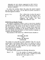
BUILD ..............................................................................
Loading BUILD .............................................................
Using BUILD ................................................................
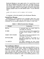
BUILD Commands ......................................................
PRINT ......................................................................
LOAD ......................................................................
INSERT ....................................................................
DELETE ..................................................................
REPLACE ................................................................
UNLOAD ..................................................................
NAME ......................................................................
ALTER ....................................................................
SYSTEM ..................................................................
BOOTSTRAP ..........................................................
General Error Messages ................................................
Start and Restart Addresses ..........................................
Auxiliary Device Handler Tape ....................................
BUILD Device Handler Format ....................................
Header Block ............................................................
Descriptor Block ......................................................
Breakdown of DCB Word ........................................
Entry Point Offset ....................................................
131
131
132
133
135
136
137
139
140
141
141
142
143
144
147
147
148
149
149
150
151
152
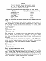
OS/8 Demonstration Run ................................................
153
Error Message Summaries ................................................
Keyboard Monitor ........................................................
Command Decoder ........................................................
Symbolic Editor ............................................................
PIP ................................................................................
ABSLDR ......................................................................
PAL8 ............................................................................
CREF ............................................................................
FORTRAN ....................................................................
SABR ............................................................................
Linking Loader ..............................................................
LIBSET ........................................................................
BUILD ..........................................................................
162
162
163
164
164
166
167
168
168
170
171
172
172
vi
os/i system
INTRODUCTION
The OS/8 Operating System is a powerfullprogramming system
designed for the PDP-8/E computer. This system permits use of a
wide range of peripherals and all available core up to 32K. OS/8
offers a versatile Keyboard Monitor which allows the user to control the flow of programs. In addition to the Keyboard Monitor,
OS/8 offers extensive I/O facilties at the Monitor levGl-many
commonly performed I/O functions such as file LOOKUPS,
ENTERS, and CLOSES have been incorporated as part of the
Monitor. These features make OS/8 a significant improvement
in small computer operating systems.
Besides the Monitor facilities, OS/8 includes a library of powerful system programs which allow the user to do program development using FORTRAN or assembly language. A brief summary
of the system programs follows:
1. Symbolic Editor (EDIT)
EDIT is used to create or modify source files for use as input to language processing programs such as PAL8, SABR,
or FORTRAN. EDIT contains powerful text manipulation
commands for quick and easy editing.
2. PAL8 Assembler
PAL8 is the assembler for the OS/8 system. PAL8 accepts
source files in the PAL language and generates absolute
binary files as output. PAL8 also generates listing files which
can be used as input to CREF.
3. Peripheral Interchange Program (PIP)
PIP allows the user to transfer files between devices which
1
are in the OS/8 system. Complete file and directory maintenance functions are available in PIP.
4. Cross Reference (CREF)
CREF operates on the listings produced by PAL8 and
SABR. It produces a sequence numbered listing and a table
indicating where each user-defined tag and literal is referenced.
5. Absolute Binary Loader (ABSLDR)
ABSLDR accepts the binary output files produced by PAL8
and loads them into core.
6 . Octal Debugging Program (ODT)
.ODT is a new, powerful octal debugging tool. All of the
features of older versions of ODT are implemented, but the
OS/8 version is designed so that no user core is needed.
7. FORTRAN
The OS/8 system contains an extensive and powerful FORTRAN package, consisting of the FORTRAN compiler,
SABR assembler, Linking Loader, and library function routines. Some of the many features of FORTRAN are:
a. FORTRAN is very easy to use. If desired, a FORTRAN source program can be compiled, loaded, and
executed with a single Teletype command.
b. Implied DO loops are permitted in FORTRAN,
c. FORTRAN contains facilities to do program chaining; this technique can be used to increase the effective program size.
d. Device independent I/O is available, as well as the
standard devices (Teletype, high-speed reader/punch,
card reader, and line printer).
8. Library Setup (LIBSET)
OS/8 LIBSET allows the user to create his own FORTRAN
run-time libraries. The standard library supplied with the
system is LIB8. By using LIBSET, the user can write his
own routines in SABR and create a library.
9. System Builder (BUILD)
BUILD allows rapid and easy alteration of the device configuration in the system. New devices can be inserted by
simple Keyboard commands. BUILD also makes interfacing
user-coded device handlers a quick and easy job.
2
OS/8 provides true device-independence. For the first time on
a PDP-8 computer, programs can be written without concern for
specific I/O devices. In running a program the user can select the
most effective I/O devices available. Further, if the system configuration is altered, programs need not be rewritten to take advantage of the new configuration.
The OS/8 system controls the copying of data from any medium
to any other medium by means of subroutine calls to execute I / O
routines. Logical names can be assigned to devices within the
system to enable symbolic referencing of devices.
Variable length I/O buffers can be specified by the user program. Large buffers ensure efficient use of storage devices and a
minimum of time spent in data transfer operations by minimizing
disk and tape motion. OS/8 takes full advantage of the RK8 disk
pack for the fast bulk storage, yet full system services are possible
with a single DECtape.
Hardware Configurations
The OS/8 system can operate with a wide variety qf devices as
the sysfern device.' The devices which can be used are:
TCOl/TC08 DECtape
LINCtape (PDP-1 2 )
TD8E DECtape
DF32/RF08 disk
RK8 disk
The TD8E can be used either with 12K of core memory, or with
8K of core memory and 256 words of Read-Only-Memory
(ROM).
If DF32 is the system device, at least 64K ( 2 platters) must be
available. In addition, if disk is the system device, high-speed
reader/punch provides a very useful tool.
The minimum OS/8 configuration is a PDP-8 series computer
with 8K of core, one DECtape used as the system device, and an
1 The term system device refers to the device on which the OS/8 system
resides and which it utilizes for system functions. Thus, DECtape Unit 0 is
the system device for a DECtape-based system. A non-system device is any
peripheral not specifically used for system functions, such as LPT:, PTR:,
DTA2:, etc.
3
ASR-33 Teletype terminal. A multiple DECtape system performs
appreciably faster than a single DECtape system. The multiple
DECtape system reduces DECtape motion since it is possible to
copy directly (without intermediate searching) from the system
DECtape to another DECtape (or vice versa) when editing or
assembling.
A typical medium-sized system might contain a PDP-8/E with
at least 8K of core, TD8E DECtape and control, and an RK8
disk pack and control. A disk system offers the additional convenience of easy and fast access to files, and large amounts of
storage.
Up to fifteen devices can be interfaced to a single OS/8 system.
These optional devices include:
As many as 8 DECtape units (TCOl/TU55, TC08/TU56 or
TD8E/TU56).
High-speed paper tape reader/punch.
Up to four RK8 disks.
Up to four RS08 disks.
Up to four DF32 disks.
Card reader (optical mark or punched cards).
Line printer.
PDP-12 LINCtape.
Any other device for which it is possible to write a device handler
in one or two pages of core.
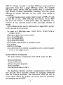
System Software Components
The main software components of the OS/8 system are five:
Keyboard Monitor
Command Decoder
Library of system programs
Device handlers
User Service Routine (USR)
The Keyboard Monitor provides communication between the
user and the OS/8 executive routines by accepting commands
from the Teletype keyboard. The commands enable the user to
create logical names for devices, run system and user programs,
save program and call ODT.
4
The Command Decoder allows the user to communicate with a
system library program by accepting a command string from the
keyboard indicating input/output files. Following the keyboard
command to run a system library program, the Command Decoder
prints an asterisk ( * ) and then accepts the command line containing the files to be used as input, file name and destination of
output, etc.
The library of system programs, as mentioned earlier, contains
the Peripheral Interchange Program (PIP), Symbolic Editor,
PAL8, an Absolute Binary Loader, a new, improved 8K FORTRAN, 8K SABR, the Linking Loader, CREF, LIBSET, and
BUILD. Other system library programs will be added as they become available.
Device handlers are subroutines designed to transfer data to
and from peripheral devices. OS/8 is able to interface with as
many as 15 different peripherals at a time. During system generation, device handlers become an integral part of the system;
both system and user programs have access to any available device. (The program BUILD allows quick and easy alteration of
any available device.)
The User Service, Routine (USR) controls the directory operations for the OS/8 system. A program can use the USR by means
of standard subroutine calls such as those used to activate device
handler subroutines. Some of the functions performed by the USR
are loading device handlers, searching file directories, creating and
closing output files, calling the Command Decoder, and chaining
of programs. The details on the operation and use of the USR are
contained in the OS/8 Software Support Manual (DEC-S8OSSMA-A-D). For normal OS/8 usage, the USR function is unseen by the user and need be of no concern.
When OS/8 is operating, the Command Decoder, Keyboard
Monitor, and USR are swapped into core from the system device
as required, and when their operation has been completed, the
previous contents of dore arg restored.
The core-resident portion of OS/8 is extremely small (256
words), allowing for a maximum use of core by user programs.
GETTING ON LINE WITH OS/8
OS/8 software is distributed to the user in a form appropriate
for his particular hardware configuration. The two general system
5
categories are DECtape and Paper Tape. This section provides the
information that the user of either type of system needs in order
to start using OS/8.
DECtape Systems
This category incrudes TCOl /TC08, TD8E, and LINCtape
(PDP-1 2) hardware configurations. Since the software is delivered
on a system DECtape (or LINCtape), it is not necessary to build
an initial system, as it is if using paper tape.
Two DECtapes are distributed with each DECtape (LINCtape)
OS/8 system. One is the system tape which contains the system
programs and all OS/8 Monitor functions. The second DECtape
contains a source of CONFIG (the standard OS/8 system configurator) and a group of binary format device handlers. CONFIG
can be used to create a certain number of standard OS/8 configurations (for details on the use of CONFIG, refer to the
OS/8 Software Support Manual, DEC-S8-OSSMA-A-D) . The
other files on the DECtape are device handlers in a format suitable
for the BUILD program. Each file contains a handler for a specific
device type. These files are to be used as input for the LOAD
command in BUILD and are described in Table 9-32 in the
BUILD section. In addition to these files, binary files of LIB8
and LIBSET have been included. LIB8.BN is a relocatable binary
file, and should be processed with LIBSET to create a FORTRAN
library. (For details concerning loading and using LIBSET, refer
to the section describing OS/8 LIBSET.)
TCOl/TC08 DECTAPE USERS
The following short procedure is used to start OS/8 on a TCO1/
TC08 system:
1. Mount the system DECtape (DEC-S8-OSYSA-A-UC) on
unit 0 (this appears as 8 on some DECtape units), making
certain to wind at least 10 feet of tape onto the empty reel.
Put the tape unit switches to REMOTE and WRITE LOCK.
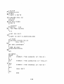
2. Toggle the following program into core from the programmer’s, console switches (refer to Appendix A for instructions concerning manual loading of programs) :
6
TCO1 /TC08 Bootstrap
761 3
7614
7615
761 6
761 7
7620)
762 1
7622
762 3
6774
1222
6766
677 1
5216
1223
5215
B 600)
7754
7555
7577
7577
022@
+7613
DrL E
T A D K60)0)
DT LA
DTSF
JMP . - 1
T A D K220
JMP . - 4
K641il,
600)
K 2 2 0 ) ~ 22e)
*7754
7577
7577
/bORD C O U N T
/CURRENT
ADDEESS
This bootstrap first rewinds unit 0 to the end zone then
starts it moving forward, reading block 0 into location 7600
in field 0. In block 0 is a larger bootstrap which continues
reading the tape, installing the resident code, and finally
turning control over the the Keyboard Monitor.
3. Set the Teletype to LINE, and start the computer at
location 7613 in field 0. Unit 0 will rock and the console
Teletype will respond by typing a dot (.) at the left margin.
At this point, OS/8 is active; DECtape unit 0 must be set
to WRITE ENABLE.
NOTE
If the Teletype does not respond properly,
check that the bootstrap was loaded correctly, that unit 0 is selected and set to REMOTE, and that the Teletype is set to
LINE. If trouble persists contact the local
DEC sales office.
TD8E DECTAPE USERS
TD8E DECtape hardware is supported in two configurations:
TD8E DECtape and 12K core; TD8E DECtape and 8K core and
256 word Read-Only-Memory (ROM).
TD8E DECtape users must run a special initialization program
before OS/8 can be used. This program need only be run once to
create the proper configuration; thereafter, the standard TD8E
bootstrap (discussed shortly), can be used to start O S / 8 .
7
TD8E Initialization Program
Follow this short procedure to run the TD8E initialization program :
1. Put the RIM loader into core in field 0 (refer to Chapter 5
of Introduction to Programming for instructions on loading
programs manually and on paper tape).
2. Place the RIM format paper tape marked TDINIT (DEC8-OTINA-A-PM) into the appropriate reader. Load this
tape with the RIM loader into field 0.
3. Mount the system DECtape (DEC-S8-OSYSA-A-UC) on
tape unit 0, setting the tape switches to WRITE ENABLE
and REMOTE. Make certain to wind at least ten feet of
tape onto the empty reel.
4. Set the Teletype to LINE and start the computer at one of
following two addresses in field 0 :
a. location 20-If
the configuration is 8K with 256
word ROM.
b. location 21-If
the configuration is 12K (and no
ROM) :
Tape unit 0 will rock several times and the Teletype will
respond by typing a dot (.). OS/8 is now active. If a system
I/O error should occur, a message will be printed on the
Teletype, and the computer will halt. In such a case, the
above procedure should be repeated; if problems persist,
consult the local DEC sales office.
After the initialization, the system DECtape contains an OS/8
system appropriate to the hardware configuration. One of the following standard OS/8 bootstrapping procedures is now used to
start OS/8.
.e
TD8E Bootstraps
8K ROM Bootstrap (PDP-8/E)
1. Mount the system DECtape on unit 0, set to WRITE LOCK,
and REMOTE. Turn the Teletype to LINE.
2: Set the switch register to 7470.
3. Press EXTD ADDR LOAD, ADDR LOAD, CLEAR, and
CONTinue. The tape bootstrap will be executed and the
Teletype will respond by typing a dot( .). OS/8 is now active.
At this point, WRITE ENABLE Unit 0.
8
12K TD8E Bootstrap
The bootstrap for the 12K TD8E is distributed on a RIM format
paper tape. The following procedure is used to start up OS/8 on a
12K TD8E system:
1. Put the RIM loader into core (any field).
2. Using RIM, load the 12K TD8E BOOTSTRAP tape (DECS8-OTBSA-A-PM) into field 0.
3. Mount the system DECtape, WRITE LOCKed and REMOTE on unit O.
4. Set the switch register to 0 and press EXTD ADDR LOAD;
set the switch register to 7300 and press ADDR LOAD,
CLEAR and CONTinue. The tape bootstrap will be executed and the Teletype will respond with a dot (.). OS/8 is
now active. At this point, WRITE ENABLE unit 0.
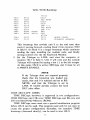
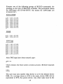
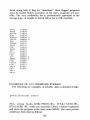
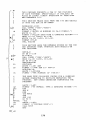
The contents of the 12K TD8E Bootstrap are included here in
the event that the user might wish to manually load the bootstrap.
7300
7301
7302
7303
7304
7305
7306
7307
7310
7311
7312
7313
7314
7315
1312
4312
4312
6773
5303
6777
3726
2326
5303
5732
2000
1300
6774
6771
7316
7317
7320
7321
7322
7323
7324
7325
7326
5315
6776
0331
1327
7640
5315
2321
5712
7354
7327
7330
7331
7332
7756
7747
0077
7400
Kl000,
RD.
*7300
TAD GET
JMS G E T
JMS G E T
SDSQ
JMP . - 1
SDRD
DCA I WCT
I S Z WCT
JMP RD
JMP I S T R T
GET,
BSRCH,
2000
TAD KlOOO
SDLC
SDSS
WCT,
JMP .-1
SDRC
AND K 7 7
TAD BM22
S Z A CLA
JMP BSRCH
I S Z .-3
JMP I GET
7 354
BM22,
STRT,
-22
-31
77
7400
9
/ P U T D R I V E IN REVERSE
/LOOK F O R END ZONE
/LOOK F O R 31 CODE
/NOW R E 4 D A L L WORDS
/ I N T O CORE
/ R E A D 12 B I T WORD
/AND P U T I T I N CORE
/LOOP U N T I L F I E L D 0
/ I S LOADED. THEN S T A R T
/ S E T MOTION & D I R E C T I O N
/ H E R E W A I T FOR E I T H E R 22
/ O R 31 CODE
/22 I S END ZONE, 31 I S
/CODE B E F O R E DATA WORD
/ I S T H I S WHAT WE WANT?
/ T H I S G E T S INCREMENTED
/ I F YES, RETUFLV
/NO> K E E P LOOKING
/LOOK F O R NEXT I N L I S T
/ S T A R T LOADING CORE
/ A T 7354
/ T H E OTHER B O O T S T R A P
/ G E T S LOADED A T 7400
Both the 8K-ROM and 12K TD8E bootstraps perform the same
function: reading record 0 of the sytsem tape into core, and then
starting it at location 7400 in field 0. The code that is read into
7400 is a larger bootstrap which installs all core resident tables
and then turns control over to the Keyboard Monitor. The 12K
system must move down to tape block 154 to accomplish the full
bootstrap, which explains the extra tape motion.
When the TD8E system (either 8K-ROM or 12K) is initialized,
only DECtapes 0 and 1 (DTAO, D T A I ) are available on the
system. The others (DTAZDTA7) are not in the system. To make
other drives available, OS/8 BUILD must be used. Reference the
BUILD section of this manual for details concerning re-configuring a system.
LINCTAPE (PDP- 12 USERS)
The following is the bootstrap procedure for PDP-1 2 systems:
1. Mount the system LINCtape (DEC-12-OSYSA-A-UO) on
unit 0, WRITE LOCKed and in the REMOTE position.
Set the Teletype to LINE.
2. Set the left switches to 0700.
Set the right switches to 0000.
Set the MODE key to LINC.
3. Press I/O PRESET.
4. PressDO.
The LINCtape bootstrap will be executed causing unit 0 to move.
When it stops, press the START 20 key. Unit 0 will again move,
and the Teletype will respond by typing a dot (.) at the left
margin. OS/8 is now active, and tape unit 0 should be set to
WRITE ENABLE.
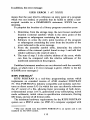
Building OS/8 From Paper Tapes
An OS/8 system can be initially constructed on a device from
the paper tapes supplied with each OS/8 kit. This is only necessary
when DECtape is not available as a system device (although initial
systems can also be constructed on DECtapes).
Building an OS/8 system from paper tapes may be done in two
distinct ways: using the CONFIG tapes supplied with OS/8, and
using the system library program BUILD.
CREATING OS/8 WITH CONFIG
The CONFIG tapes are standard configurations supported by
10
OS/8 which contain device handlers for the system. They allow
the user to build a disk based system using the following devices':
DF32 disk ( 2 platters)
RF08 disk ( 1 platter)
RK8 disk
The CONFIG tapes should be used when high-speed paper tape
input is not available. Since the paper tape reader/punch (devices
PTR, PTP) on systems created with CONFIG utilize the ASR-33
as the reader/punch, the CONFIG method of building OS/8 should
be used only by those systems not having the high-speed unit. (If
high-speed I / O is available, the initial system can be constructed
using OS/8 BUILD. See the section entitled Creating OS/8 with
BUILD.)
Follow this procedure to create an OS/8 system using the lowspeed reader:
1. Load the RIM and Binary Loaders. For convenience, assume that the Binary Loader is in field 0. (This is not required, it may go into any available memory field.)
2. Load the OS/8 binary tape (DEC-S8-OOS8A-A-PB) into
field 0 using the Binary Loader. (See Appendix A for details of using the Binary Loader.) The tape should read in
and stop on binary leader/trailer. If no checksum error has
occurred (i.e., AC=O), proceed with step 3; if the AC is
non-zero after step 2, try reloading the tape.
3. Several configuration tapes (CONFIG), corresponding to
the different possible system deyices supported by OS/8, are
supplied with the OS/8 kit. These are:
CONFIG Tape #
System Device
DEC-S8-ODRKA-A-PB
DEC-S8-ODRFA-A-PB
DEC-S8-ODDFA-A-PB
RK8 disk
RF08 disk ( 1 platter)
DF32 disk ( 2 platters)
(The source of CONFIG is distributed on three separate
paper tapes labeled DEC-S8-0CFGA-A-PAl, -PA2, -PA3
respectively. )
2 If DECtape or LINCtape is the system device no initial system generation is required.
11
After the OS/8 binary tape has been loaded in properly,
place the appropriate CONFIG binary tape in the low-speed
reader and press CONTinue; this loads the tape into field 0.
If the AC = 0 proceed to step 4. If the AC is non-zero, repeat step 3.
NOTE
The system device to be used must be
WRITE ENABLEd at this point. Start the
computer at location 0200 in field 0. This
causes parts of the Monitor to be written to
the system device. The computer should halt
with 7777 in the AC. (If the AC does not
contain 7777, go back to step 2; if the AC
is 7777, proceed to step 4.)
4. Place the Command Decoder binary tape (DEC-S8OCMDA-A-PB) in the low-speed reader, and load it using
the Binary Loader (which is still in core in memory field 0).
If the AC = 0 at the completion of loading, proceed to step
5. If the AC is non-zero, repeat step 4.
5 . Start the computer at 0200 in memory field 0. This causes
the Command Decoder and ODT to be written to the system
device. The Keyboard Monitor is then activated-the Teletype prints a dot (.), and OS/8 is active.
OS/8 is up and running; the default device is the same as the
system device. ABSLDR (which resides on the system device)
should now be used to load the various system programs., Refer to
the section entitled Loading OS/8 System Programs for details.
Disk Bootstrap
Once an OS/8 system has been built on a disk (RF08/DF32 or
RK8), it may occasionally be necessary to start (bootstrap) the
system into operation when nothing is in core. For example, whenever an RK8 disk cartridge is placed into its slot and is to be used,
the system should be bootstrapped. Also, if a program error is encountered such that the contents of page 7600 in either field 0 or
field 1 are in doubt, the system should be restarted.
The bootstrap for the RF08 and DF32 disks is:
12
Location
Contents
07750
0775 1
07752
07753
07754
7600
6603
6622
5352
5752
After depositing the bootstrap, the computer should be started at
location 7750 in field 0. The Keyboard Monitor should respond
with a dot (.). If it does not, repeat the procedure. If an error
persists, consult the local DEC sales office.
The RK8 bootstrap is as follows:
Location
Contents
00030
0003 1
6733
503 1
The computer should be started at location 30 in field 0.
NOTE
If a PDP-12 is being used, execute an I/O
PRESET in 8 mode before starting at location 30.
Restart Address
If the system ever ceases apparent response to the user, the computer can be restarted at either locations 7600 or 7605 in field 0.
Starting at 07600 causes the contents of locations 0-1777 to be
saved on the system device. These locations are then available
when the Keyboard Monitor resumes operations. Starting at 7605
does not save the core locations. Starting at 7605 saves time on a
DECtape configuration.
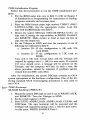
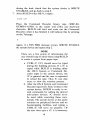
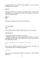
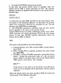
CREATING OS/8 WITH BUILD
If a high-speed reader unit is available, the BUILD program can
be used to create the initial OS/8 system from paper tapes. Follow
this procedure to create OS/8 with BUILD:
1. Load the RIM and Binary Loaders into field 0.
2. Using the Binary Loader, load the BUILD binary tape
(DEC-S8-OBLDA-A-PB) into core.
13
NOTE
Since BUILD is made up of three binary
segments it will be necessary to depress
CONTinue twice to completely load BUILD.
3. After the entire BUILD binary tape has been loaded with
no checksum errors, (i.e. AC = 0), start the computer at
location 0200 in field 0. BUILD prints:
HI SPEED?
If a high-speed reader is contained in the system, respond
YES (followed by a carriage return?));if only a low-speed
reader is available, respond NO.
4. Make certain the system device is WRITE ENABLEd (and
in REMOTE if using DECtape or LINCtape).
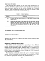
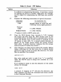
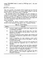
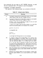
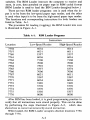
5. BUILD asks the user to specify which type of device will be
used as the system device as follows:
SY s=
Enter the system device to be used in the following form:
DEV=n
where DEV represents one of the legal replies taken from
the following list. =n is optional and meed only be used to
indicate the number of physical disk platters which are pres.ent if the system device is RF08 or DF32. The possible
replies and the maximum value of n which can be used for
each one are indicated below.
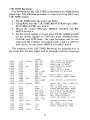
Table 1 System Devices
Maximum n
Device
TC08
TD8E
LINC
DF32
RF08
RK8
ROM
(TC08 DECtape)
(12K TD8E)
(LINCtape)
(DF32 disk)
(RF08 disk)
(RK8 disk)
(TD8E with Read-Only-Memory)
3 Unless otherwise indicated, all commands should be followed by a carriage return.
14
n must be a digit in the range 1 to 4. If no value for n is
specified, a value of 1 is assumed. If a response other than
a digit is entered, the message:
BAD
#
is generated, and the system request is repeated. If n is specified as a digit but is too large for the device specified, the
system request is repeated. For example:.'
sys=
SYS=TC08=4
is illegal since 4 is too large for the TC08 specification.
-
SYS=RKB=C
BAD #
SY
s=
is illegal because C is not a digit.
and
-
SYS=DF32=3
(where $ = ALT MODE) are both legal replies; n is assumed to be I in the first case.
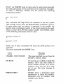
6. BUILD writes data on the system device, and then types:
LOAD
OS8t
At this point load the OS/8 System binary tape (DEC-SSOQS8A-A-PB) in the proper reader and strike any keyboard character. BUILD will load and write out the various
parts of OS/8. If a SYS ERR message occurs at any time
4 In cases in which there may be some discrepancy as to whether a character was typed by the user o r by a system program, that typed by the system will be underlined.
during the load, check that the system device is WRITE
ENABLEd, and go back to step 2.
7. After BUILD writes OS/8, it types:
LOAD C D f
Place the Command Decoder binary tape (DEC-S8OCMDA-A-PB) in the reader and strike any keyboard
character. BUILD.wil1 load and write out the Command
Decoder; when it has finished it will indicate this by printing
on the Teletype:
Again, if a SYS ERR message occurs, WRITE ENABLE
the system device and repeat step 2.
NOTE
There are a few points of information the
user should keep in mind when using BUILD
to create a system from paper tape.
a. CTRL/C ( t C ) should never be typed
during the building process. If a tC is
typed while BUILD is loading either
the OS/8 System or Command Decoder tapes to the system device, the
tC is ignored and the user is requested
to reload the tape. Thus tC can only
serve to slow the creation process.
b. After the OS/8 System and Command
Decoder tapes have been written to the
system device, BUILD is ready to accept commands for adding the desired
non-system devices. tC should never
be used while executing these commands. The system device at this point
contains no peripheral devices and no
bootstrapping facilities, and typing a
CTRL/C will serve no purpose. (If
the user does type a tC, it is necessary
16
to type START to continue system
configuration. )
c. If, by accident, the OS/8 System and
Command Decoder binary tapes are
loaded in reverse order, the system will
be improperly generated and the building procedure must be repeated.
d. After the system has been generated
using BUILD, the directory of the system device will contain the ABSLDR
program. Any directory previously contained on the device will be destroyed
when the system is generated from
paper tape.
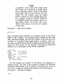
The OS/8 Monitor now resides on the system device. If the system had been created using the CONFIG tapes, device handlers
would already have been inserted into the system. Since BUILD
was used in the creation process, the only device which is available
is SYS-the system device, and BUILD must now be used to insert
the desired devices. The following commands are used to create
the initial system. (After following this procedure, the user may
wish to refer to the section at the end of this manual devoted to
BUILD for detailed information concerning its use.)
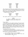
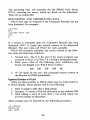
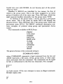
In response to the $ typed by BUILD (indicated here by an
underline), type the following (each command line shquld be followed by typing the ALT MODE key, which echoes as $):
--BBB III NNN
-BIN
PT8E, PTP$
PT8E, PTR$
AS338
LPB8S
These commands activate the following devices :
Permanent Device Name
Device
PTP :
PTR:
TTY:
LPT :
High-speed punch
High-speed reader
Keyboard
LPO8 line printer
Next, DECtapes (if required) may be inserted in the system.
17
Execute o w of the following groups of BUILD commands, depending on the type of DECtape available. The permanent names
for DECtapes are DTAO-DTA7, the names for LINCtapes are
LTAO-LTA7 :
TCOl/TC08
--SB II NN
--SS II NN
-S I N
TC08, DTA0S
TCB~JDTA~S
T C 0 8 , DTAZS
TC08, DTA38
TC08, DTA4S
BIN TC08, DTA59
S I N TC08, DTA68
S I N TC08, DTA7S
--
TD8E
.-
S I N TDE(A, D T A 0 S
S I N TDBA, DTA1 S
LINCtape
After DECtapes have been entered, type:
-
SBOOTS
which initiates the final system creation process. BUILD responds
with:
DSK=
The user may now specify what device is to be the default device
DSK. If a carriage return or SYS is the reply, device DSK will be
equivalent to SYS, the system device. Any other reply must be the
18
permanent name of a device which appeared in one of the IN
commands. For example:
-
DSK= DTA 1
will cause DTA1 to be used as the default device. If the device
specified is not a file structured device, the request is repeated, as
in the following example :
DSK=
-
DSK=LPT
If the device specified is not active, BUILD prints:
dev
N O T FOUND
DSK=
-
After DSK has been specified, BUILD types out the message
SYSTEM BUILT
and the OS/8 Keyboard Monitor is activated.
BUILD is still in core, and at this time it would be to the user’s
advantage to SAVE the copy of BUILD just used. This is done by
the following procedure:
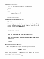
-
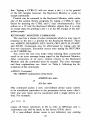
.SAVE
SYS BUILD 0 - 7 5 7 7 > 1 0 0 0 0 - 1 7 5 7 7 = 0 ; 2 0 0
This copy of BUILD reflects the current status of the system. It
can be loaded and rerun with the command:
See the section concerning BUILD for details of using BUILD
effectively.
19
Loading OS/8 System Programs
After an OS/8 system has been created from paper tapes using
either the procedure involving CONFIG or BUILD, the system
programs should be loaded using ABSLDR, which is resident on
the system device.
NOTE
Users with DECtape (LINCtape) as the system device already have core images of the
system programs on their tape. Thus, this
section may be disregarded.
Use the following procedure to load the various system programs. When an up-arrow (?) is printed by the Command Decoder,
typing any character on the keyboard in response will cause the
tape to be read into core.
PIP (DEC-S8-OPIPA-A-PB)
Place the PIP binary tape into the appropriate paper tape reader,
and type the following responses to the . and * printed by the
Keyboard Monitor and Command Decoder, respectively:
-
. R ABSLDR
-* P T R : = 1 3 0 0 0 ( 8 9 ) 8
(RETURN key)
($=ALT MODE key)
When loading is complete, the Keyboard Monitor responds with
a dot (.). Type:
.SAVE
SYS PIP
(RETURN key)
PIP has been saved on the system device.
EDITOR (DEC-S8-OEDTA-A-PB)
Place the Editor binary tape in the reader, and load as follows:
. R ABSLDR
--*PTR:
/9$
(RETURN key)
($=ALT MODE key)
The Editor is read and the Keyboard Monitor responds with a
dot (.). Type:
-
.SAVE
SYS EDIT
(RETURN key)
20
The Editor is now written on the system device.
PAL8 (DEC-S8-OPALA-A-PB)
Place the PAL8 Assembler binary tape in the reader, and load
as follows:
SLDR
--*. RP T RA:B198
(RETURN key)
($=ALT MODE key)
The tape is read and the Keyboard Monitor responds by printing a dot (.). Type:
- SAVE
SYS PALE;
(RETURN key)
PAL8 is now written onto the system device.
FORTRAN (DEC-S8-LFORA-A-PB)
Place the FORTRAN Compiler binary tape in the reader, and
load as follows:
. R ABSLDR
--*PTR:
SB
1
(RETURN key)
($=ALT MODE key)
When loading is complete, the Monitor responds with a dot (.) .
Type :
-SAVE
S Y S FORT
(RETURN key)
FORT has been saved on the system device.
SABR (DEC-S8-OSABA-A-PB)
Place the SABR Assembler binary tape into the reader, and load
as follows:
-*. RP T RABSLDR
- : 15%
(RETURN key)
( $ =ALT MODE key)
When loading is complete, the Keyboard Monitor responds with
a dot (.). Type:
-SAVE
SYS SABR
(RETURN key)
21
SABR has been saved on the system device.
Linking Loader (DEC-Sf3-OLLDA-A-PB)
Place the Linking Loader binary tape in the reader. Load as
follows:
. R ABSLDR
--*PTR:
/98
(RETURN key)
($=ALT MODE key)
When loading is complete, the Monitor responds with a dot (.).
Type :
- SAVE
SYS LOADER
(RETURN key)
The Linking Loader has been saved on the system device.
LIB8 (DEC-St3-OLIBA-A-PB)
Place the Library Setup (LIBSET) (DEC-St3-OLSTA-A-PB)
binary tape in the reader. Load as follows:
-. R A B S L D R
-*PTR: / G = 1 2 6 0 0
(RETURN key)
(RETURN key)
When this tape is loaded, the system responds by printing an
asterisk ( * ) . Now place the LIB8 relocatable binary tape in the
reader and type:
*/ S $
($=ALT MODE key)
The tape is read, and a LIB8,RL file is created on the system
device.
CREF (DEC-S8-OCRFA-A-PB)
Place the CREF binary tape in the reader. Load as follows:
SR A B S L D R
--*PTR:
198
(RETURN key)
($=ALT MODE key)
After loading, Monitor responds with a dot (.). Type:
-.
SAVE SYS C R E F
(RETURN key)
22
CREF is now written onto the system device.
This completes the building of the OS/8 system.
KEYBOARD MONITOR
T h e Keyboard Monitor provides communication between the
user and the OS/8 executive routines by accepting commands
from the Teletype Keyboard. The Keyboard Monitor allows the
user to create logical names for devices, run system and user
programs, save programs and to call ODT.
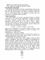
System Conventions
The OS/8 system has various conventions which are quickly
mastered by even the novice programmer. Naming procedures
for devices and file extensions have been designed as simple
mnemonics. OS/8 makes use of the terms: “word”, “page”,
“record”, and “block” as units of storage. In directory listings
and elsewhere file lengths are referenced in terms of blocks (or
records). The terms are defined as follows:
1 block = 1 record = 2 pages = 256,, words
Each word is composed of 12 bits. The internal structure of the
PDP-8 words and pages is described in detail in Chapter 2 of
Introduction to Programming.
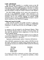
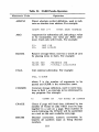
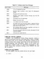
PERMANENT DEVICE NAMES
Each device in the OS/8 system is referenced by means of a
standard permanent device name. These names are used in all
I/O designations and are listed in Table 2.
These names are the device names assigned when the OS/8
system is configured. They may be changed by reconfiguring the
system; however, caution should be observed when doing so.
Certain system programs operate on the premise that a specific
device name will be present in the system; for instance, PIP makes
use of the device name TTY: as the default device when doing
directory listings, CREF assumes LPT: as the default output
device, and the Command Decoder uses device DSK: as the
general default output device. Therefore, it is suggested that the
following device names remain present on the system:
SYS:
DSK :
TTY:
LPT :
23
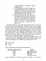
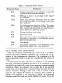
Table 2 Permanent Device Names
Permanent Name
I/O Device
SYS
System device (disk if the system has a large disk
-RK8 or RF08; otherwise DTAO).
DTAn
DECtape n, where n is an integer in the range 0
to 7, inclusive.
LTAn
When using BUILD, LINCtapes may be called
LTA rather than DTA. n is an integer in the range
0 to 7 inclusive.
DSK
The default storage device for all files. The assignment of DSK is specified at system generation
time. Usually DSK is the disk on a single disk system or DTAO on a DECtape system.
?TY
Teletype keyboard and printer.
PTP
Paper tape punch.
PTR
Paper tape reader (before accepting input, the system prints an up-arrow (r), to which the user replies by typing any key).
CDR
Card Reader
LPT
Line printer (performs a form feed before it begins printing output from a new program).
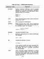
FILE NAMES AND EXTENSIONS
Files are referenced symbolically by a name of up to six alphanumeric characters followed, optionally, by a period and an extension of two alphanumeric characters. The extension to a file
name is generally used as an aid for remembering the format of
a file.
In most cases the user will want to conform to the standard
file name extensions established for OS/8. If an extension is not
specified for an output file, some system programs append assumed
extensions. Where an extension for an input file is not specified
by the user, the system does a search for that file name with the
default extension. Failing to find such a file, a search is then
done for the original file without an extension. For example, if
PROG were specified as an input file to PAL8, the Command
Decoder would first look for the file PROG.PA (since .PA is the
24
standard extension for PAL8 input files). If PROG.PA were
not found, the Command Decoder would try to find the file PROG
(with no extension). As not all system programs utilize default
extensions, reference the following table and the individual system
programs for details:
Table 3
Assumed Extensions
Extension
Meaning
.sv
Core image file or SAVE file; appended to a file name
by the R, RUN, SAVE, and GET Keyboard Monitor
commands.
.FT
8K FORTRAN source file.
.SB
8K SABR source file.
.PA
PAL8 source file.
.BN
Absolute binary file (default extension for a Binary
Loader input file. Also used as the default extension for
PAL8 binary output file).
.RL
Relocatable binary file (default extension for a Linking
Loader input file. Also used as the default extension for
an 8K SABR output file).
.MP
File containing a loading map (used by the Linking
Loader).
.LS
PAL8 or 8K SABR assembly listing output file.
.TM
Temporary file generated by FORTRAN or SABR for
system use.
For example, if the user types:
-.RUN
D S K PROG
the file PROGSV (on device DSK) is run, if found. If the user
types :
-.RUN
DSK PR0G.A
then PR0G.A (on device DSK) is run, if found.
25
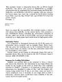
Using the Keyboard Monitor
Each command to the Keyboard Monitor is typed at the
Teletype keyboard. If corrections are necessary, they must be
made before entering the command line to the system. A command line is entered to the system by typing either the RETURN
key, which causes a carriage return/line feed operation but no
printed character, or an ALTMODE (ESCAPE on some Teletype Keyboards), which prints a $, but causes no carriage return/
line feed. Correcting mistakes is accomplished by typing the RUBOUT key, which deletes the last character typed and causes a
backslash (\) character to be printed followed by the character
which was deleted. Successive RUBOUTS each cause one more
character to be printed and deleted. The first non-RUBOUT
character typed (after the last RUBOUT in a sequence) causes
a closing backslash (\) to be printed, thus enclosing the deleted
characters with backslashes. For example :
User types:
.RUN DSK (RUBOUT) (RUBOUT) (RUBOUT) D T A l :FILE
Teleprinter
Shows: .RUN DSK\KSD\DTAl : F I L E
Keyboard
Monitor sees:
.RUN D T A l :FILE
If at any time an input line becomes so corrected that it is no
longer intelligible to the user, he can verify the contents of the
line by typing the LINE FEED key. This causes the entire input
line to be echoed as the Keyboard Monitor would see it at that
point. The line is not considered to be entered to the system, and
the user can proceed to edit, delete, or enter the line at his
discretion.
For example:
User types:
.RUN DTA3\3\2:PRG
System echoes: RUN DTAZ: PROG
\G\OG
( L I N E F E E D key typed)
A command line may be deleted completely before it is entered by typing a' CTRL/U (produced by pressing the CTRL key
and U key simultaneously). This echoes as a TU,and returns control to the Keyboard Monitor without accepting the current input
26
line, Typing a CTRL/U will not cause a dot (.) to be printed
at the left margin; however, the Keyboard Monitor is ready to
accept commands.
Control can be returned to the Keyboard Monitor while under
any of the system library programs by typing a CTRL/C (produced by pressing the CTRL and C keys simultaneously). This
echoes as a TC and the Keyboard Monitor signals that it is ready
to accept input by printing a dot (.) at the left margin of the teleprinter paper.
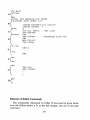
KEYBOARD MONITOR COMMANDS
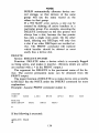
The user has a choice of nine commands which he may type in
response to the dot (.) printed by the Keyboard Monitor. These
are: ASSIGN, DEASSIGN, GET, SAVE, ODT, RUN, R, START,
and DATE, Commands may be abbreviated by typing only the
first two characters. Execution occurs after typing the RETURN
or ALT MODE key.
Any errors the user may make while utilizing these commands
result in an error message being typed by the Keyboard Monitor.
After occurrence of an error, control returns to the Keyboard
Monitor and the command must be retyped. The error messages
and their explanations are listed in Table 4, following the descriptions of the commands.
ASSIGN Command
The ASSIGN command is of the form:
.ASSIGN dev udev
or
.AS dev udev
This command causes a new, user-defined device name (udev)
to be considered equivalent to the permanent device name (dev) .
Only one user name can be associated with a single device at a
time. For example:
-.AS DTAl
IN
causes all future references to IN to refer to DECtape unit 1,
(references can still be made to the device DTAl also).
If a user-defined device name is not indicated, any existing
27
user-defined name is removed and only the permanent device name
is valid. For example:
DTAl
-.AS
.AS DTAl
-
IN
The above sequence changes the name of DECtape 1 to IN and
then back to simply DTAl again.
The user-defined name is composed of up to four alphanumeric characters, the first of which must be alphabetic; the userdefined name takes procedence over the permanent name. Deviceindependent programs are easily possible since a change in the
user name of a device by means of the ASSIGN command can
change the operation of a routine without changing the code.
Although user-defined names may be four characters long, the
name may not be unique in the OS/8 system. (This is due to the
fact that the device name is internally coded in only one word.)
A three or four character name may be tested for uniqueness by
typing an ASSIGN command as follows:
.AS name
If a ‘name NOT AVAILABLE’ message results, the name is
unique within the current system, is not in the system tables, and
therefore may be used.
All user-defined device names of one or two characters in
length are unique.
DEASSIGN Command
The DEASSIGN command is of the form:
.DEASSIGN
or
.DE
and causes all permanent device names to be restored, discarding all previous user-defined device names. For example :
-.AS
-DE
DTAl IN
28
causes DECtape 1 to be assigned the name IN. The DEASSIGN
command removes the name IN from the system tables; DTA1
can no longer be referenced as IN.
GET Command
The GET command is of the form:
.GET dev file.ex
or
.GE dev file.ex
The GET command loads core image files (.SV format, not
ASCII or binary) into core from a device. This device (dev) is
specified along with the file name (file) and an optional file name
extension (.ex). The file is loaded into core with its core control
block; the core control block is then moved to a special area on
the system device, where it is maintained on the system device
and contains information about the file such as its starting address and areas of core occupied by the file. Also contained is a
Job Status Word, which is saved (with the SAVE command) and
loaded in location 7746 of field 0 with the file to indicate what
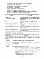
parts of core the file uses and how, as follows:
Job Status Word
Meaning
Bit Condition
Bit 0 = 1
File does not load into locations 0-1777 in
field 0, (0000-1777).
Bit 1 = 1
File does not load into locations 0-1777 in
field 1, ( 10000-11777).
Bit 2 = 1
Program must be reloaded before it can be
restarted because it modifies itself during execution.
Bits 3 - 9
Unused, and reserved for future expansion.
Bit 10 = 1
Locations 0-1777 in field 0 need not be saved
when calling the Command Decoder overlays.
Bit 11 = 1
Locations 0-1777 in field 1 need not be saved
when calling the USR.
29
A core control block is created for each core-image file when the
file is created by the Linking Loader, ABSLDR, or the SAVE
command.
If a file name extension is not specified to the GET command,
the extension .SV (for core-image file) is added automatically to
the file name. For example:
-
.GE DTA3 OH
attempts to fetch the file OH.SV from device DTA3.
The GET command is typically used before a debugging session with ODT. GET is used to load the object program into
core, then ODT is called, and the program can be altered and/
or debugged (see the section on ODT for more details).
SAVE Command
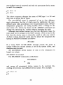
The SAVE command is of the form:
.SAVE dev file.ex a-b,c ,...;s=n
or
.SA dev file.ex a-b,c ,... ;s=n
where
a-b,c, ... are the addresses of the areas and locations in core to
be saved. (In this case, locations a through b, location c, and any other specified locations.) a, b, and c
are five digit locations. (The first digit represents the
field.) When a single location is indicated (c) the
entire page on which c is located is saved.
;s
is the starting address of the file.
=n
n is a four digit octal number representing the contents of the Job Status Word (see the GET command).
The program currently in core is saved on the device (dev)
specified, with the file name indicated (file.ex). If an extension
is not specified, the extension .SV is automatically added by the
system. If the remaining arguments are not given, the required
information is taken from the current core control block (refer
to the GET command).
30
There are some restrictions on the SAVE arguments which
should be noted :
1. Each set of limits (a-b) must be in the same field and not
cross field boundaries. For example:
-
.SAVE
SYS F O O 0 2 0 0 - 2 0 2 0 0
is illegal since the limits transcend a field boundary.
2. No two sets of limits can overlap; (Le. a-b, c-d must not
overlap). In fact, once a location on a specific page is included in the limits, any other location on that core page,
whether overlapping or not, will produce an error message.
For example:
-.SAVE
SYS FOO 0 - 1 7 7 , 2 0 0 - 3 7 7
islega1,but
-.SAVE
SYS FOO 0 - 2 0 0 , 2 0 1 - 3 7 7
isillegal.
3. In SAVEs involving memory fields other than field 0, the
field must be specified before each of the two core limits.
If the field is unspecified, field 0 is assumed. Thus:
-.SAVE
-.SAVE
SYS F O O 2 0 2 0 0 - 0 3 7 7
is illegal, while
SYS FOO 2 0 2 0 0 - 2 0 3 7 7
is legal.
4. SAVE files can include 7600 in any field. However, extreme
care must be taken when manipulating these areas, particularly in fields 0 and 1, as the system resident code could
be destroyed by GETting area 07600-07777. It is suggested that SAVEs involving 7600 be limited to fields above
field 2.
If an error message is printed in response to a SAVE command,
the program currently in core has not yet been saved.
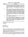
Examples of SAVE commands are:
-.SAVE
DSK CPROG 5 5 , 1 0 5 0 0 - 1 0 5 7 7 ;
31
10502
This statement saves the program in core on the disk as a file
named CPROG.SV. The areas of core saved are locations 0 to
177 in field 0 and locations 400 to 577 of field 1 (when a single
core location or part of a page is indicated, the entire page on
which the locations occur is saved). The starting address of the
program is 502 in field 1. The core control block is updated to
contain this information and the old Job Status Word is taken
intact from the original core control block.
-
. S A V E DSK CPROG
The above statement causes the program in core to be saved on
device DSK under the name CPROGSV where the areas of core
to be saved are taken from the core control block currently
available.
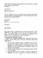
ODT Command
The ODT command is of the form:
.ODT
or
.OD
This command causes the system ODT to be loaded into core
and started. ODT is a system overlay, and as such takes up none
of the user’s program area unless the breakpoint feature is used,
in which case ODT uses locations 4, 5, and 6 of every field in
which a breakpoint had been placed. When using ODT to debug
programs, the user-defined device names cannot be used; each
I/O device must be called by its permanent device name.
ODT is described in greater detail later in this manual.
RUN Command
The RUN command is of the form:
.RUN dev file.ex
or
.RU dev file.ex
The RUN command, like the SAVE command, handles only
core-image files. The file indicated (file.ex) on the device specified (dev) is loaded into core and its core control block is moved
to the system scratch area. The program is started at its starting
32
address. The RUN command is equivalent to a GET and a START
command.
If an extension to the file name is not specified, the extension
.SV is automatically added to the file name. For example:
-.RU
DTA1 PROG
causes the file PROG.SV on DECtape 1 to be loaded and started.
R Command
The R Command is of the form:
.R file.ex
and is similar to
.RUN SYS file.ex
This command handles only core image files from the system
device. The file is loaded and started. If the file name extension
is not specified, the extension .SV is automatically added.
The R command differs from the RUN command in that a core
control block is not written to the system device. In order to save
a program which does not have its core control block in the usual
location on the system device, all the optional arguments of the
SAVE command must be explicitly stated. System programs are
most often called using the R command, since they need not be
resaved.
To call a program which is to be later up-dated and saved, use
of the RUN or GET commands is suggested.
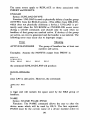
START Command
The START command is of the form:
.START nnnnn
or
.ST nnnnn
The program currently in core is started at location nnnnn. If the
argument nnnnn is omitted, the program is started at the starting
address specified in the core control block.
For example:
33
starts the program in core at location 555 in field 1.
starts the program at the starting address given in the core control
block,
The START command clears certain areas of core-the device
handler in core table and the Command Decoder output area.
DATE Command
The DATE command is of the form:
.DATE mm/dd/yy
or
,DA mm/dd/yy
The DATE command sets up the date in the system for purposes
of dating directory entries and listings, printing on program output,
etc. For example:
6 D A 3/13/70
L.
indicates that the date is March 13, 1970.
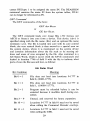
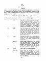
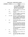
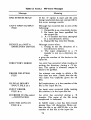
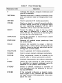
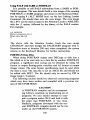
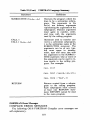
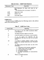
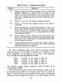
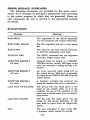
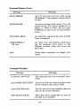
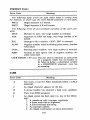
Keyboard Monitor Error Messages
Table 4 lists the generalized and command Keyboard Monitor
errors. All errors return control to the Keyboard Monitor and the
command must be retyped. xxxx indicates the core location where
the error was detected.
Table 4 Keyboard Monitor Error Messages
Message
Meaning
BAD ARGS
The arguments to the SAVE command are not consistent and violate
restrictions listed in 1, 2, 3 under
SAVE command.
BAD CORE IMAGE
The file requested was not a coreimage file (it could have been an
ASCII or binary file).
BAD DATE
The date has not been entered correctly (using slashes), or incorrect
arguments were used.
34
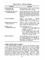
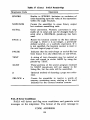
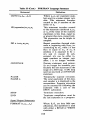
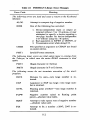
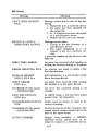
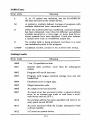
Table 4 (Cont.) Keyboard Monitor Error Messages
Message
Meaning
ILLEGAL ARG.
The SAVE command was not expressed correctly; illegal syntax used.
MONITOR ERROR 2 AT xxxx Attempt made to output to a
WRITE-LOCKed device, usually
DECtape; or an error has occurred
reading/ writing a directory.
MONITOR ERROR 5 AT xxxx An error occurred while doing I/O
to the system device. This error is
normally the result of not WRITEENABLE the system device.
MONITOR ERROR 6 AT xxxx This message results if a directory
overflow has occurred (no room for
tentative file entry in directory).
name NOT AVAILABLE
The device with the name given is
not listed in any system table, or it
is not available for use at the moment
(check the device in question), or
the user tried to obtain input from
an output-only device (such as the
high-speed paper tape punch).
name NOT FOUND
The file with the name given was not
found on the device indicated, or the
user tried to input from an outputonly device.
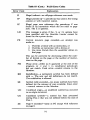
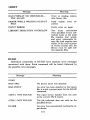
NO!!
The user attempted to start (with
.ST) a program which cannot be
started. The user must not restart
any user program or system library
program which modified itself while
in core (bit 2 of the Job Status Word
is set; see the GET command for
details.)
An I/O error has occurred while
SAVE ERROR
saving the program. The program remains intact in core.
An error occurred while doing I/O
SYSTEM ERR
to the system device. The system
should be restarted at 7600 or 7605.
Do not press CONTinue, as this is
sure to cause further errors.
35
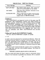
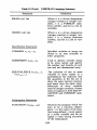
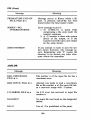
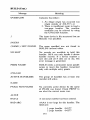
Table 4 (Cont.) Keyboard Monitor Error Messages
Message
TOO FEW ARGS
Meaning
An important argument has been
omitted from a command. For example,
- RUN
DSK
would generate this message, as the
program to be run has not been
entered in the command.
USER ERROR 0 AT xxxx
An input error was detected while
loading the program. xxxx refers to
the Monitor location where the error
was generated.
abcd?
Where abcd is not a legal command;
for example, if the user typed:
-HELLO
the system would echo:
HELLO?
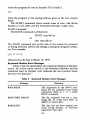
COMMAND DECODER
Once a system program has been called via the Keyboard Monitor, that system program may make use of the Command Decoder
by permitting the user to enter a list of I/O files and devices. The
Command Decoder prints an asterisk ( * ) at the left margin to
indicate it is ready to accept a command string.
The Command Decoder uses the same keyboard characters as
the Keyboard Monitor for the purpose of correcting typing mistakes. The RUBOUT key deletes one character per rubout. The
CTRL/U (TU) combination deletes an entire line. CTRL/C returns the user to the Keyboard Monitor, and the LINE FEED key
causes the entire line to be printed on the teleprinter paper as it
appears in the Teletype input buffer.
The description of files, file names, extensions, devices, and device names is contained in the section concerning the Keyboard
36
Monitor; this description pertains to the Command Decoder as
well.
Command Decoder Input String
The expected string for I/O specification takes the form:
DEV :OUTPUT FILES<DEV :INPUT FILES
(While the left angle bracket (<) is the accepted divider character
between output and input files, the back arrow (+) may also be
used.) There may be 0-3 output files and 0-9 input files, depending
on the requirements of the individual system program. The particular I/O string used with each system library program is described in its respective section.
For example:
*DTA1 2 XY 1 >LPT:<DSK: PROG
The PAL8 assembler would use the first output file (DTA1 :XY 1)
for the binary output of the assembly and the second output device
(LPT:) for the listing. DSK:PROG or PROG.PA is the input
source file.
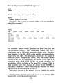
Multiple file specifications are separated by commas. If no output files are indicated, the left angle bracket can be omitted. For
example :
-*DSK: PROG
would cause the file PROG on device DSK to be accepted as an
input He.
The forms in which I/O files may be specified in a command
string are illustrated below:
File Specifications
Form
DEVICE:FILE
NAME
Example
Meaning
~ D T A ~ : F I L EThe
~
I/O file is to be found
under the specified name
(FILE1) on the device indicated (DTA3 :)
37
File Specifications
Form
-
Meaning
Example
DEVICE:
-
+LPT:
When a device is indicated
without an associated file name,
the device is usually a nondirectory device. (If a directory device is used, the device
can be read, but not written;
for example, referencing DTA0
causes the entire DECtape
Unit 0 to be used as the input
file. DSK: is always the default
output device.)
FILENAME
%NAME<DTA~:PROG
A file name used without an
associated device indicates
that the file will be found on
an assumed device. For all
output files and the first input
file, the device is assumed to
be DSK:. The example indicates DSK:NAME as an output file. For input files after
the first, the device is assumed
to be the device of the previous entry. For example:
-*DSK: PROG 1 < D T A 1 : F I L E 1
J
FILE2, FILE3
causes the three input files to
be taken from DTA1 .
NULL FILE
-
*,LPT:<DTAl:
QUEST, DTA2: S T A R
38
The absence of an explicit
file specification has different
meanings in context, and is indicated by a comma which is
not preceded by a file designation. For output files, a null
file indicates that there is no
File Specifications
Form
Example
Meaning
'output file for this position. If
the example given were an input line to PAL8, the first output file (binary) would not
be generated, but the listing
would be output to the line
printer. For input files, a null
file indicates that the device
of the most recent entry is to
be used as a non-directory
device :
-++
D S K : A < P T R :,,
This input string allows three
paper tapes to be read from
the high-speed reader.
EXAMPLES O F COMMAND STRINGS
Some examples of command strings specifying I/O are shown
below with appropriate explanations.
Example 1:
-
*DSK:BINARY,LPT:<SOURCE
The file named SOURCE is the input file on device DSK: The
two output files are BINARY on DSK, and a second file on the
line printer (LPT). The PAL8 assembler uses this format; however, the assembler also adds the extension .BN onto the file
labeled BINARY. Thus, the output file on device DSK: will be
named BINARY.BN.
Example 2:
-* INPUTlr INPUT2r I N P U T ~PTR:
J
J
39
This is a string of input files with no output file. Notice that the
left angle bracket is not necessary if there are only input files specified. This type of input might be given to one of the loaders
(which do not require output files). Three files are taken from
device DSK and then two are taken from the paper tape reader
(PTR: ,) .
Example 3:
The input files C and D are taken from device XYZ (which could
be any device with the user-defined named XYZ). The-output
files are a file named A on DTA2 and a file named B on DSK.
Example 4:
-* > L P T :
< SRC
The input file is named SRC and is on DSK. The two output files
specified are one null file (no output file in that position) and a
file to be sent to the line printer (LPT).
Example 5 :
-* P T R :
J
>
D T A l :X
As in Example 2, this is another input only file string. The first
input file comes from the paper tape reader, as does the second
(PTR: ,,) . The third input file is named X and is on DTAl.
Example 6 :
-*A< TTY:
J
Both input files in this example come from the Teletype (generally the low-speed reader). The single output file is named A and
is stored on DSK.
INPUT/OUTPUT SPECIFICATION OPTIONS
In addition to output and input files which are indicated on the
file specification line to the Command Decoder, there are various
options which can also be indicated on this line. These options
are interpreted by the individual system programs and are covered
40
in detail in the sections describing the various programs. Options
are either numbers or alphanumeric option characters.
Numbers used as options are generally contained in the
command line with the equal sign (=) or square brackets ([ 1)
construction. The alphanumeric option characters are set off from
the I/O specifications by the slash ( / ) character for single character options, and parentheses for a string of single characters.
The usage of the slash, parentheses, equal sign, and square
brackets is explained below. These explanations will serve as
references and format specificationsonce the user has learned from
reading about each individual program which options he will be
needing.
The format for input to the Command Decoder looks generally
like the following:
DEV: OUPUT FILES<DEV :INPUT FILES/OPTIONS
The Slash Construction
A single alphanumeric option character is preceded by a slash
and can occur anywhere in the input line, even in the middle of a
name, although the usual position is after the input files. For
example :
-
*TTY: / L < D S K : A B
is equivalent to:
-*TTY: < D S K :A B / L
The option specified is L, which PIP interprets as a command to
list the DSK directory beginning at file AB.
The Parentheses Construction
Any number of option characters can be grouped together inside parentheses. This construction is also valid anywhere in the
input line. For example:
-*OUT: X < I N :Y AQZ
(
)
is equivalent to:
-*OUT: X < I N :Y / A / Q / Z
41
The Equal Sign Construction
An octal number up to seven digits long and preceded by an
equal sign (=) may optionally be used as an indicator. This
construction is often used to set a starting address, but may be
assigned other functions as well. It may only occur once in a line
and must be followed by a separator character (comma, left
angle bracket, back arrow, ALT MODE key or RETURN key)
or by other options and a separator character. The following
example uses the equal sign construction and indicates three separate options:
-
* F I L E 1 = 1 00 2 C AQX 1 > F I L E 2
Interpretation of options and = sign numbers varies depending
upon the program which called the Command Decoder. See the
individual system programs for details.
The Square Bracket Construction
The square bracket construction can only occur immediately
after an output file name and consists of an open bracket, a decimal
number between 1 and 255, and a close bracket. The square
bracket construction is generally only used by the more sophisticated user to optimize file storage.
The open bracket ([) is produced by holding down the SHIFT
key while typing a K (i.e., SHIFT/K); the close bracket (1) is
produced by typing a SHIFT/M. This construction is used to
provide an upper limit on the number of blocks (256 words per
block) to be contained in the output file in order to allow the
system to optimize file storage. For example:
-*BINARY[ 1911 L I S T I N G C 2001< S O U R C E / 8
The output files are a file named BINARY on device DSK: having
a maximum length of 19 blocks, and a file name LISTIN (only
six characters are significant) on the device DSK with a maximum
length of 200 blocks. The input file is SOURCE on device DSK;
the option specified is 8, which is interpreted by the program
being run.
42
Notes On Device Handlers
The device handlers supplied with the OS/8 system have certain operating characteristics which the user should understand.
Most of these are extremely simple and require no action on the
part of the user. Some device handlers perform additional operations for the user when I/O is being performed on a given device.
The device handler for the high-speed paper tape reader, before
reading a tape, prints an up arrow ( t ) and waits for the user to
type any single character at the k e y b ~ a r d .This
~ gives the user
time to check the reader to be sure the tape is loaded correctly,
and it facilitates reading multiple tapes. Characters are read from
the paper tape and packed into an input buffer. The end of the
paper tape or a full input buffer causes the buffer to be made
available to the user program. Typing CTRL/C while the tape is
moving causes a return to the Keyboard Monitor.
The handler for the high-speed paper tape punch unpacks characters from the output buffer and punches them on paper tape.
Typing CTRL/C causes a return to the Keyboard Monitor. The
punch must be manually turned on before an attempt is made
to output to that device.
In addition to the handler for the high-speed reader/punch (type
PC8-E), a similar handler is available for the ASR-33 Teletype
low-speed reader/punch. This handler allows users not having
high-speed I/O to read and punch binary format tapes. (The
standard TTY handler cannot be used for binary format tapes, as
the binary format can appear as control characters to the handler.)
The operation of this handler is exactly the same as that for the
PC8-E reader/punch, and can be made a part of the system by
altering the device configuration. For more information, refer back
to Getting On Line With O S / 8 , or to the section concerning Using
BUILD, which describes how to insert new devices into the system.
The line printer performs a form feed operation before beginning an output task. The characters are unpacked from the output
buffer and printed. A form feed is also produced following the
completion of an output task. Typing CTRL/C while the line
printer is in operation causes a return to the Keyboard Monitor.
5When using PAL8, the user is required to load the source tape three
times for the three passes of the assembler; each pass generates an up arrow.
43
A CTRL/Z found in the output buffer causes printing to terminate
and a form feed to be produced.
The line printer handler for the LP08 (LE8) printer is capable
of using either the 80 or 132 column printers. The program
BUILD can be used to make the appropriate change. (Refer to
the ALTER command in the section concerning BUILD for this
procedure. )
The Teletype handler performs I/O transfers between the Teletype keyboard and an input buffer, or between an output buffer and
the teleprinter. A CTRL/O typed while output is being printed
terminates printing of the current output buffer. A CTRL/C
typed at any time during input or output causes a return to the
Keyboard Monitor. Typing CTRL/Z as input terminates input
and gives an end-of-file indication to the calling program. The
teleprinter echoes all typed input and performs a line feed operation
after any typed carriage return. The Teletype handler should not
be used to read binary tapes from the low-speed reader.
The device handler for the card reader reads cards in alphanumeric format from either a punched card reader or an optical
mark card reader. Card format can have up to 80 characters per
card; trailing blanks are deleted from each card. Blank cards cause
a carriage return/line feed to be entered into the data stream.
Typing CTRL/C while cards are being read terminates reading
and returns control to the Keyboard Monitor. Typing CTRL/Z
terminates further reading and acts as if an end-of-file card was
read. (An end-of-file card contains a +- character in Column 1
(0-8-5 punch) with the remaining columns blank. Either CTRL/Z
or the end-of-file card is necessary to terminate reading.) It is not
possible to RUN or GET a program from the card reader as these
commands assume a directory device. Any DECtape other than the
system device (if it is a DECtape system) can be interrupted with
a CTRL/C, returning control to the Keyboard Monitor. DECtape
Unit 0 on a DECtape system must never be WRITE LOCKed
while operating OS/8.
The DSK and SYS device handlers work automatically without any user intervention. Consult the OS/8 Soffware Support
Manual (DEC-S8-OSSMA-A-D) for additional information on
devices and device handlers.
44
Command Decoder Error Messages
The following is a complete list of the error messages which the
Command Decoder generates if a command string is improperly
input.
Table 5
Command Decoder Error Messages
Message
Meaning
ILLEGAL SYNTAX
The command line was formatted incorrectly.
name DOES NOT EXIST
The device with the name specified
could not be found in the system tables.
name NOT FOUND
The file with the flame specified does
not exist on the device indicated.
TOO MANY FILES
More than three output files or nine
input files were specified.
SYMBOLIC EDITOR
The Symbolic Editor is used to create and modify ASCII source
files so that these files may be used as input to other system programs (such as FORTRAN, SABR, and PAL8).
The Editor considers a file to be divided into logical units called
pages. A page of text is generally 50-60 lines long, and corresponds
approximately to a physical page of a program listing. (Note that
this is not the same as a core memory page.) The’ Editor reads
one page of text at a time from the input file into its internal buffer where the page becomes available for editing. The Editor contains commands for creating, modifying, or deleting characters,
lines, or complete logical pages of text.
Calling and Using the Editor
To call the Editor from the system device, type:
R EDIT
in response to the dot (.) printed by the Keyboard Monitor. The
system prints an asterisk ( * ) at the left margin, and in answer to
the asterisk, the user types the device designation and the output
45
file name, a left angle bracket, and the input device and file designation (s) . For example :
-*DSK: ABCCPTR:
>
DSK: A A 1
causes input from the paper tape reader and from a file named
AA1 on DSK. The output file is named ABC and is stored on
DSK.
Once I/O file designations are entered, the Symbolic Editor is
ready to accept commands from the keyboard and signifies its
readiness by printing a number sign ( # ) at the left margin. This
symbol occurs whenever the Editor is waiting for a command.
Any device which operates in ASCII mode and has a device
handler in the system is available for use by the Editor. For example, the high and low-speed reader/punch, DECtape, disk,
card reader and line printer are each legal devices. The Editor
only operates properly on ASCII files, however. No error message
is given if non-ASCII files are input to the Editor, but the results
of operations are garbled.
As many as nine and as few as zero input files are permitted.
If the number of input files is zero, (that is, a new file is to be
created using the Teletype keyboard) the Editor allows input from
the keyboard via the Append command.6 The Editor uses a keyboard input routine which is independent of the OS/8 Teletype
handler, thus it is not necessary to specify TTY: as an input device
if text is to be created. (It is, in fact, recommended that TTY: not
be used as an input device, as input buffering may cause a loss of
characters on input.) Commands which attempt to read from any
other device (when no file name is specified) are disabled, and a
question mark (?) appears when a Read command is attempted.
The Editor allows only one output file. If no output file is specified, the only output operations which may be performed are L
(list buffer on TTY:) or V (list buffer on LP08 line printer).
Chaining to the Editor is not permitted, and will produce a
fatal error message (?5tC). Attempts to restart after this error will
produce NO!! frsm the Keyboard-Monitor.
6 See Example Using the Editor for an illustration of using the Editor to
create a program.
46
EDITOR OPTIONS
The following two options are the valid I/O specification options for the Editor. (The format for I/O specification options has
been previously described in the section detailing the Command
Decoder. After reading these options, the reader is advised to turn
to that section to review the various formats.)
Table 6
Editor Options
Option
Meaning
/B
Convert two or more spaces to a TAB when reading from
input device.
/D
Delete the old copy of the output file (if one exists) before
opening the new output file on the device. If / D is not
used, the old copy of the output file is not deleted until all
data has been transferred to the new file by an E or Q
command.
For example, the I/O specification line:
-*DTA2 :F I L E < DTA1 :ARG/D
deletes FILE on DTA2 (if such a file exists) before creating a new
FILE on DTA2.
Special Key Commands to the Editor
The Editor can be considered as operating in two different
modes. During command mode, the Editor prints a # at the left
margin of the teleprinter paper indicating that it is waiting for a
command from the keyboard. Text mode is the condition of the
Editor when it is processing various editing and I/O commands
(such as Insert and Append).
The following commands allow the user to transfer between
modes. (These commands are produced by pressing the CTRL
key and the appropriate character key simultaneously.)
47
Table 7
Command
CTRL/C
Editor Key Commands
Mode in Which
Used
Meaning
Text and command Returns control to the Keyboard Monitor. The text buffer
mode
is retained and the Editor remains accessible to the user
with the START command. In
text mode, text between the last
carriage return and the TC is
lost.
The START command can be
used to restart the Editor as
follows:
TC
--*
START
START recalls the Command
Decoder to accept new I / O
file designations. When the
START command is given, and
the previous output file is not
closed, that output file and the
contents of the output buffer
are deleted.
CTRL/ 0
Text Mode
Stops the listing of text. Re-
turns control to Command
Mode.
CTRL/FORM
Text Mode
Returns the Editor to Command Mode.
CTRL/U
Text Mode
Typing CTRL/U while entering text from the keyboard
causes text in the current line
to be ignored. A carriage returdline feed is generated and
the line may be retyped. (The
command is equivalent to typing rubouts back to the beginning of the line.)
Other special Editor characters used to represent numbers or
perform erasures are listed in Table 8 :
48
Table 8
Character
Example
.+1c
.-7L
.L
/
/-7L
/
RUBOUT Key
Special Characters
- 5L.
Meaning
The dot (.) character is used as the
current line counter character. The
dot can be used alone, with + or an integer, or any place where a
number can be used.
The slash character is similar in use
to the dot and represents the highest numbered line in the text buffer.
Typing the RUBOUT key in text
mode deletes one character from
the text buffer and causes a backslash to be printed. The erasure is
done right to left up to the last
CR/LF. Typing the RUBOUT key
in command mode causes the entire
command line to be deleted.
Editor Text Buffer
In text mode, the Editor performs I/O operations on text stored
within the text buffer. Text is input to the Editor buffer until a
form feed is encountered on input. A line of text is terminated by
a carriage return. If no carriage return is present, the text entered
on that current line is ignored. The buffer has room for approximately 5600 (decimal) characters. When text has been input to
the extent that there are only 256 decimal locations available in
the buffer, the TTY rings a warning bell. From this point on,
whenever a carriage return is detected during text input, control
returns to the Editor command mode and the TTY bell is rung.
This line-at-a-time input may continue until the absolute end of
buffer is encountered. At this point, no more text will be accommodated in the buffer; a '?' is printed and control returns to command mode.
TEXT COLLECTION
The OS/8 version of the Editor contains an automatic text collector which reclaims buffer space following the use of a D (delete),
S (Search), or C (Change) command. Formerly, deleted text was
49
not physically removed from the buffer; now this text is removed
by the text collector, and the necessary pointers updated. If a full
buffer condition is reached, the user may output lines of text
(using the Punch command, for example), and then delete these
lines from the buffer-text collection is automatic and always occurs on the three commands mentioned above.
NOTE
If extremely large amounts of text are deleted, the text collection process could take
several seconds. For small amounts of text,
no appreciable time is lost.
Search Mode
There are two types of searches available in the Editor. The
first is the standard character search, and the second is the character string search which allows the user to search for a combination of characters. Each is explained in turn.
STNGLE CHARACTER SEARCH
The single character search is of the form:
or
or
#S
# nS
#m,nS
where m and n represent line numbers (m<n), and S initiates the
search command.' This search command searches the entire text
buffer or the line(s) indicated for the search character. The search
character is typed by the user after he types the RETURN key
which enters the command, and does not echo on the teleprinter.
The Editor prints the contents of the entire buffer or the indicated
line(s) until the search character is found. When the search character is found, printing stops and the user may type one of the
following:
7 A command summary is included in Table 10 at the end of this
section.
50
Result
text at that
Option
text
Enter
point at
which the search character was
found and printing stopped.
CTRL/G (TTY bell rings)
Change the search character
to the next character typed;
search continues. If the character is not contained in the
line, the remainder of the line
will be typed and control will
be returned to command mode.
CTRL/FORM
Continue searching for the next
occurrence of the character.
RETURN key
End line here, deleting all subsequent text on that line.
LINE FEED key
Make two lines out of the current line by inserting a carriage return at this point.
RUBOUT key
Delete characters from this
line. Each rubout echoes a
backslash (\) for each character deleted. When all characters have been deleted,
echoing of ‘Y stops.
CHARACTER STRING SEARCH
The character string search can identify a given line in the buffer by the contents of that line or any unique combination of characters. This search returns the line number as a parameter that can
be used to further edit the text. There are two types of string search
available: intra-buffer search and inter-buffer search.
Intra-Buffer Character String Search
The intra-buffer search scans all text in the current buffer for
a specified character string. If the string is not found, a ? is printed
and control returns to command mode. If the string is found, the
number of the line which contains the string is put into the current
line counter and control waits for the user to issue a command.
51
Thus, searching for a character string in this manner furnishes a
line number which can then be used in conjunction with other
Editor commands. This provides a useful framework for editing,
as it eliminates the need to count lines or search for line numbers
by listing lines.
An intra-buffer search is signalled by typing the ALT MODE
key (which echoes as $) in response to the Editor’s #. The user
then types the string to be found (up to 20 characters long-any
additional characters typed are echoed but not included in the
search). The search string cannot be broken across line boundaries.
Typing a single quote (’) terminates the character string and
causes the search to be performed beginning at line 1 of the text
buffer. Use of the double quote (”) causes the search to begin
at the current line +l. (Use of ’ and ” as command elements prohibits their use in the search string.)
For example, assume the text buffer contains the following text:
ABC DEF GJO
lABB3C4D5E6
STRINGABCD
.
The user wants to list the line that contains ABC; this could be
done by typing:
The search begins with line 1 and continues until the string is
found. The current line counter is set equal to the line in which
the string ABC occurred, and the L command causes the line to be
printed as follows:
ABC DEF GJO
Control returns to command mode, awaiting further commands. If
the user wanted to find the next reference to ABC, he could type:
-
# “L
52
In this case, " is a command which causes the last string searched
for to be used again, with the search beginning at the current line
+ l . It is no necessary to enter the search string again. The command may be used several times in succession. For example, if the
user wanted to find the fourth occurrence of a string containing the
characters FEWMET he could type:
-#$FEWMET'
L
"""
This command will list the line which contains the fourth occurrence of that string. The L (List) command (or any other command code) can be given following either ' or ". The L command
causes the line to be listed when and if it is found.
In order to clear the text string buffer, the user can type:
The system will respond with a question mark and the text string
buffer is cleared.
The properties of the commands ' and " allow for easy and
useful editing, as the following example illustrates. In order to
change the CIF 20 to CIF 10, the user can give the following
commands:
-C#$DUM,
' $ C I F 2a"C
I F 10
/NEW F I E L D
(CTRL/FORM)
The above set of instructions first causes the Editor to start at line
1 and search for the line beginning with DUM,. A search is then
made for CIF 20, starting from the line after the line containing
DUM,. When this string is found, the line number of the line containing the string CIF 20 becomes the current line number. The C
(Change) command is given, and the user then changes the line
to the correct instruction.
Since this search feature produces a line number as a result,
any operations which can be done by explicitly specifying a line
number can be done by specifying a string instead. For example:
-# $ S T R I N G ' +4i
53
will list the fourth line after the first occurrence of the text STRING
in the text buffer.
- BLABEL 1
#
9
' > SLAREL 2, "L
will list all lines between the two labels, inclusive.
-#BPFLUG '
S
will do a character search on the line which contains PFLUG. (The
user types the search character after typing the RETURN key that
enters the line.)
In cases where both strings and explicit numbers are used,
strings should be used first. For example, the following commands:
-#l+SBAD!'L
will not list the next line after the string BAD! occurs. The correct
syntax is:
-#SBAD!'+lL
Inter-Buffer Character String Search
The inter-buffer search scans the current text buffer for a character string. If the string is not found, the current buffer is written
to the output file, the buffer is cleared, and the next buffer is read
from the input device. The search then resumes at line 1 of the new
buffer. This process continues until either the string is found or no
more input is left. If input is exhausted, control returns to command mode with all the text having been written to the output file.
If the string is found, control returns to command mode with the
current line equal to the number of the line containing the first
occurrence of the string. For example, a command to find the
character string GONZO may appear as follows:
The J command initiates an inter-buffer search; the $ is printed
automatically by the Editor, and the user types in the character
54
string he wishes to search for. The search proceeds, and when the
string is found, control returns to command mode. The user types
the .= construction to discover the number of the line in the current
buffer on which the string is contained. To find further occurrences
of the string GONZO, the user can use the F command. The F
command uses the last character string entered to search the buffer starting from the current line count
1.
+
-#F
-# .=e)lp)6
The above example causes a search for the string GONZO starting
at the current line
1. If no output file is specified to the J or F
commands, the Editor reads the next input buffer without attempting to produce any output. This provides an easy way of paging
through text for a particular string.
After the J or F commands have processed the entire input file,it is necessary to execute either an E or Q command to close the
output file. If this is not done, the file will be deleted by the
Monitor.
The following two commands may be used to abort the string
search command, once given:
+
Command
Explanation
CTRL/U
A CTRL/U will return control to the Editor command mode if executed while entering text in a
string search command; the string search command is ignored, as in the following example:
-#J
-SWORD? U
The inter-buffer search for the characters WORD
was aborted by the user typing TU before terminating the string with ’ or ”.
RUBOUT
Executing the RUBOUT key while entering text
for a string search causes the text so far entered
to be ignored and allows a new string to be inserted. Editor answers the command by typing $,
as in the following example:
55
4
An example of the use of the character string search is contained
in the OS/8 Demonstration Run, at the end of this chapter.
Editor Error Messages
Errors made by the user while running the Editor may be of two
types. Minor errors (such as an Editor command string error, an
attempt to execute a read or write command without assigning a
device, or a search for a non-existent string) will cause a question
mark to be typed at the left margin of the Teletype paper. The
command may be retyped. Major errors cause control to return
to the Keyboard Monitor and may be due to one of the causes
listed in Table 9. These errors cause a message to be typed in
the form:
?ntC
where n is an error code and tC indicates that control has passed
to the Keyboard Monitor.
Table 9 Editor Error Codes
Error Code
JO
1
2
3
4
5
Meaning
Editor failed in reading a device. Error occurred in
device handler; most likely a hardware malfunction.
Editor failed in writing onto a device; generally a
hardware malfunction.
File close error occurred. For some reason the output file could not be closed; the file does not exist
on that device.
File open error occurred. This error occurs if the
output device is a read-only device or if no output
file name is specified on a file-oriented output device.
Device handler error occurred. The Editor could not
load the device handler for the specified device. This
error should never occur.
An attempt was made to CHAIN to the Editor. This
is not permitted; the Editor must be loaded by a
RUN or R command.
During the editing of a file, the output device specified in the
command string may become full before the editing process is complete. If this is the case and a write is attempted on that device,
an error occurs. The output file is closed, the message:
FULL
*
is printed; control returns to the Command Decoder for a new
set of I/O specifications. The user must indicate a new output file
which will contain the text that would not fit on the output device,
and any further editing the user wishes to do. Since the contents
of the text buffer are retained through this procedure, no text
will be lost if this error occurs.
NOTE
If no output file is specified when control
returns to the Command Decoder, the Editor returns to the Command Decoder again;
this continues until an output device is specified. However, specifying an improper
output device (such as PTR:) will cause a
fatal error and the output buffer will be
destroyed.
Assuming the output device is valid, the Editor will continue
the operation which filled the old file, putting all output into the
new output file. m e r editing is campkted, the output-files should
be combined with PIP. The entire process may appear as follows:
-.R#Y
EDIT
*OUT< I N
-$#JS T R I N G
-FULL
* D T A 3 :O U T 2 c
c
#.L
-#. D
TAD S T R I N G
#E
-FULL
-* D T A 4 : O U T 3 <
Device DSK: is full; DTA3: is specified
as the new output device, and editing
continues.
Device DTA3: has become full; DTA4:
is now specified as the output device, and
editing continues.
57
4..
At this point the output “file” is the series of files-DSK:OUT,
DTA3 :OUT2, and DTA4:OUT3. When output is split like this,
the split may have occurred in the middle of a line. Therefore, the
output files should never 5e edited separately as the split lines will
then be lost. In a case such as this, the files should be combined
with PIP as follows:
. R PIP
--*DTAB:OUT<DSK:OUT,
DTA3:OUT2, DTA4zOUT3
The new file, OUT, may then be edited.
Example Using the Editor
The following example illustrates both the use of the Editor to
create a new file, and a few of the commands available for editing.
Sections of the print out are coded by letter-corresponding explanations follow the example.
A
The user calls EDIT; the output file will be called FILE and
will be stored on the default device. There is no input file
since one will be created from the Teletype keyboard. The
Append command is used to insert text into the empty buffer.
B Text is inserted.
C
The user makes a mistake and uses the RUBOUT key to correct it.
D
More text is added.
E The user notices a typing mistake he has made several lines
back in the text. He types a CTRL/FORM to finish the Append command, searches for the illegal character, corrects it,
and then lists the line.
F
The P command writes the current buffer into the output file
placing a form feed after the last line. The K command deletes
all text in the current buffer, in preparation for a new page
of text.
G The user inserts new text using the Append command. When
he is finished, he types a CTRL/FORM to end the command,
and
H closes out the file. Control returns to the Keyboard Monitor.
58
/SR
EDIT
J
P T R HANDLER F O R THOSE
HIGH SPEED I / O
IFZERO N O H S P T + L I S T < X L I S T >
<
IFNZRO NOHSPT
0
CLA CLL CMX\L
/SET LINK
JMS P S E T U P
KSF
JMP P T P C N T
/KEYBOARD FLAG OFF
K RT
AND P T P 1 7 7
TAD P T P M 3
KRT'\ S
KRS
S Z A CLA
JMP P T P C N T
Summary of Editor Commands
The commands discussed in Table 10 can each be given whenever the Editor prints a # at the left margin, and are of the general form:
59
#X
#n X
or
# m,nX
where m and n represent the line number designation, ( m 6 ) and
X represents the command letter. The command is entered to the
Editor with the RETURN key. Numbers used in Editor commands
are decimal numbers.
Table 10 Symbolic Editor Commands
Command
Format
A
#A
B
#B
C
#nC
#m, nC
D
#nD
#m, nD
Meaning
Append the following text being typed
at the keyboard until a form feed
(ASCII 214 or CTRL/FORM) is
found. The form feed returns control
to command mode. Text input following the A command is appended to
whatever is present in the text buffer.
List the number of available core locations in the text buffer. The Editor
returns the number of locations on the
next line. To estimate the number of
characters that can be accommodated
in this area, multiply the number of
free locations by 1.7.
Change the text of line n to the line(s)
typed after the command is entered
(typing a form feed terminates the
command).
Delete lines m through n and replace
with the text line(s) typed after the
command is entered. (Typing CTRL/
FORM indicates the end of the inserted lines.) The C command utilizes
the text collector in altering text.
Delete line n from the buffer.
Delete lines m through n from the
buffer. The space used by the line to
be deleted is reclaimed as part of the
DELETE function. (Refer to Text
Collection in the section entitled Editor Text Buffer.)
60
Table 10 (Cont.) Symbolic Editor Commands
Command
Format
Meaning
~ _ _ _ _
~~
E
#E
Output the current buffer and transfer
all input to the output file, closing the
output file.
F
#F
Follows a string search. Look for next
occurrence of the string currently being searched for. (See section under
Search Mode concerning Inter-Buffer
Character String Search.)
G
#G
Get and list the next line which has a
label associated with it. A label in this
context is any line of text which does
not begin with one of the following:
space
(ASCII 240)
/
(ASCII 257)
TAB
(ASCII 211)
RETURN (ASCII 215)
At the termination of a G command,
control goes to command mode with
the current line counter equal to the
line just listed.
Get and list the first line which begins
with a label, starting the search at
line n.
Insert whatever text is typed before
line 1 of the text buffer. The form feed
(CTRL/FORM) terminates the entering process and sends control to the
command mode where Editor prints
a #.
Insert whatever text is typed (until a
form feed is typed) before line n of
the text buffer.
#nG
I
#I
#nI
J
#J
Inter-buffer search command for character strings (see section under Search
Mode concerning Inter-Buffer Character String Search).
K
#K
Kill the buffer. Reset the text buffer
pointers so that there is no text in the
buffer .
61
Table 10 (Cont.) Symbolic Editor Commands
Command
Format
Meaning
NOTE
The Editor ignores the commands
nK or m,nK. This is to prevent
the buffer from accidentally being
destroyed if the user means to
type a List command (m,nL).
L
List entire contents of the text buffer
on the teleprinter.
List line n of the text buffer on the
teleprinter.
List lines m through n of the text buffer on the teleprinter. Control then
returns to command mode.
M
Move lines m through n directly before line x in the text buffer. The $
character represents typing the dollar
sign key (SHIFT/4). The old occurrence of the moved text is removed;
no buffer space is lost.
N
Write the current buffer to the indicated output file and read the next
logical page.
Write the current buffer to the' output
file, zero the buffer, and read the next
logical page. This is done n times until
the nth logical page is in the text buffer. Control then returns to command
mode.
The N command cannot be used with
an empty text buffer. ? is printed if
this is attempted.
Write the entire text buffer to the output buffer.
Write line n of the text buffer to the
output buffer.
Writes lines m through n, inclusive, to
the output buffer. When this buffer is
62
Table 10 (Cont.) Symbolic Editor Commands
Command
Format
Meaning
full, the text is output to the indicated
output file. The P command automatically outputs a FORM character
(214) after the last line of output.
Q
#Q
R
#R
S
#S
T
#T
V
Y
Immediate end-of-file. Q causes the text
buffer to be output. All text written
into the output buffer is then written
into the output file and the file closed,
with control returning to the Keyboard
Monitor.
Read from the specified input device
and append the new text to the current
contents of the buffer. If no input file
was indicated or if no input remains,
a ? is printed and control returns to
command mode.
Character search command (see the
section entitled Search Mode).
Punch trailer tape. Causes 32 frames
of blank tape to be written into the
output buffer (only to non-directory
devices).
If an LP08 line printer is available,
the V command causes the entire text
buffer to be listed on the line printer.
List line n of buffer on the line printer.
List lines m through n inclusive on the
line printer.
Skip to a logical page in the input file,
without writing any output. For example:
-5Y
#
reads through four logical pages of
input, deleting them without producing
output. The fifth page is read into the
text buffer and control automatically
returns to command mode.
63
Table 10 (Cont.) Symbolic Editor Commands
Command
Format
Meaning
$
#$TEXT"
#$TEXT'
Perform a character string search for
the string TEXT. (See the section under Search Mode concerning IntraBuffer Character String Search). Following a string search, #" causes a
search for the next occurrence of the
string.
#
))
.= or .:
/=or /:
By typing these characters the user
can obtain the current line number
(.=) and the last line number in the
text buffer (/=). The number is
printed by the Editor immediately
after the user types the equal sign.
(The colon character is equivalent to
the equal sign.)
>
$>
Equivalent to .+1L; list the next line
in the text buffer on the teleprinter.
<
$<
Equivalent to .-1L; list the next line
in the text buffer on the teleprinter.
LINE FEED
Key
Equivalent to .+1L; list the next line
in the text buffer on the teleprinter.
PERIPHERAL INTERCHANGE PROGRAM (PIP)
PIP is the OS/8 system program which is used to transfer files
between devices, merge and delete files, and list, zero, and compress directories.
Calling and Using PIP
To call PIP from the system device the user types:
R PIP
in response to the dot printed by the Keyboard Monitor. The Command Decoder then prints an asterisk at the left margin of the teleprinter paper and waits to receive a line of I/O files and options.
PIP accepts up to nine input files and performs output to a single
output file; options generally are placed at the end of the command string.
64
Since PIP performs file transfers for all file types (ASCII, Image
or SAVE format, or Binary), there are no assumed extensions assigned by PIP to file names for either input or output files. All
extensions, where present, must be explicitly specified.
Following completion of a PIP operation, ‘the Command Decoder again prints an asterisk at the left margin and waits for another PIP I/O specification line. The user can return to the Keyboard Monitor by typing CTRL/C.
PIP OPTIONS
The various options allowed on a PIP I/O specification line
are detailed in the following table. Either /A, /Byor /I is generally indicated for each transfer; if none of these are specified,
the system proceeds as though /A had been typed.
Table 11 PIP Options
Option
Meaning
/A
Transfer files in ASCII mode. The file is modified as it is
copied: embedded blank tape and rubouts are deleted and
leaderltrailercode is reduced to a standard length. PIP may
also do some editing of the input file under control of the
/Cand / T options (see below).
Transfer files in Binary mode (used for absolute and relocatable binary files). Leader/ trailer code is reduced to a
standard length, but the checksum is not recalculated.
/B
NOTE
If several absolute binary files are combined
into one, the / S option must be indicated to
/C
/D
the Absolute Loader in order for the files to
load properly. (The Linking Loader will not
load combined files.)
Eliminate trailing blanks. Valid in ASCII mode only.
Delete the old copy of the output file before doing any
data transfer. If / D is not used, the old copy is not deleted
until all input has been processed. For example:
-*DTAl:OFILE-=DTAB:NFILE/D
will first delete file OFILE on DTA1, and then transfer the
data from NFILE to a new OFILE. / D is useful when insufficient room exists on the output device for both the old
file and the new file.
65
Table 11 (Cont.) PIP Options
Option
Meaning
/ D may be used to delete up to three files at a time by
specifying the files to be deleted as output files and not
specifying any input files. For example:
-*OLDABC> DTA3: F I L E S / Dc
This command string deletes OLDABC from DSK, and
FILES from DTA3.
/E
List directories in extended form (the lengths of the empty
files are also listed).
/F
List directories in short form (file names only).
/G
Ignore any errors which occur during a file transfer and
continue copying.
/I
Transfer files in image mode. Used to transfer core image
(SAVE format) files, and any other files which do not fall
into either ASCII or Binary categories.
/L
List the directories of the input devices onto the output file
starting at the file specified. Notice that in this case the input file itself is not transferred, only the directory. The
directory listing is in extended form, but empty files are
excluded.
=n
Save n extra words per file entry in the directory to contain
descriptive information about the file. For use with the / Z
and / S options only. Typing =1 allows the date of the file
creation to be automatically stored in the directory. (=1 is
assumed after I Z or I S options unless otherwise specified.
Specifying =O will still reserve one extra word per entry.)
/S
Move all files from the input device to the output device,
eliminating any embedded empty files. All device names
should be explicitly stated, as no default devices are assumed. The directory of the output device will contain only
those files that appeared on the input device. Whenever a
/S is initiated, PIP asks:
ARE Y O U SURE?
The user responds with a “Y” if he wishes the compression;
typing any other character aborts the command.
66
Table 11 (Cont.) PIP Options
Option
/T
Meaning
In addition to compressing directories, /S provides a mzans
of copying one device to another. DECtapes, for example,
can be copied by compressing one DECtape onto another
tape.
Perform the following conversions of special characters:
Character
Is Converted To:
TAB
/Y
/Z
enough spaces to reach the next
TAB stop (every eighth position)
Vertical
TAB
5 LINE FEEDs
FORM FEED
9 LINE FEEDs
/Toption is valid in ASCII mode only.
Copy the OS18 System Area (records 0, 7-67) between
the output and first input file. Both devices must be file
structured devices. If no file name is specified after a device
name, the System Area of that device is assumed. If the
/Z option is used with /Y,a zeroed system directory is
placed on the output device before the system transfer
takes place. A system directory indicates that file storage
starts at record 70 rather than record 7.
Zero directory of output device before file transfer. Before
using a DECtape for the first time, the / Z option should
always be used to create an empty file directory. No input
files are specified. For example:
-*DTAB:/Z<=l
One extra word per entry is used if no "=" is specified.
Thus, the DATE word is always left available in a new
directory.
If an attempt is made to zero the directory of the system
device, the message:
ZERO SYS?
is printed. A response of 'Y'will zero the directory; any
other response will abort the command and return control
to the Command Decoder.
67
No data transfer occurs if no input files are specified. Thus, as
mentioned previously, /Z can be used to zero a directory, and /D
can be used to delete a permanent file without creating a file. For
the three directory listing options (/E, /F, / L ) , if no output device is specified, the device TTY; is assumed. If no input device is
specified, device DSK: is assumed.
EXAMPLES OF PIP SPECIFICATION COMMANDS
The following are legal command strings to PIP. When PIP
has completed an operation, control returns to the Command Decoder for additional input.
Example 1 (ASCII Transfer) :
R PIP
-L*SYS:
BLACK<PTR:
This command string transfers a tape from the paper tape reader
to a file on the system device under the name BLACK. PIP assumes that the input tape is in ASCII format. (Control returns
to the Command Decoder, therefore, the .R PIP command need
only be given once.)
Example 2 (ASCII File Merge) :
-*DTA3 :MERGE<DTAl: F I L E 1 F I L E 2
>
This command string instructs PIP to merge the ASCII files FILE1
and FILE2 on DTA1 into one ASCII file, MERGE, on DTA3.
Example 3 (Binary Transfer) :
The above command reads a binary paper tape from the paper
tape reader and creates a binary file BIN.BN on the device DSK.
Example 4 (Image Transfer) :
PIP transfers the core image file PAL8.SV from the device DSK
to GAG.SV on the system device.
68
NOTE
A problem occurs when files longer than
255 blocks are transferred in Image Mode
from a directory device. If this is attemped,
the transfer will not end with the real endof-file, but will continue until the output
limit is reached; an error message will occur.
For example, trying to transfer FORT.PA
or SABR.PA from the directory device using Image Mode will cause this error.
ASCII mode must be used for all transfers
of this type.
Example 5
(Directory Listing) :
This command string produces an extended listing of the device
DSK on the Teletype. An extended listing contains all files with
their associated lengths, and all empty spaces in the directory. For
example, an extended listing might appear as follows. (The current date is printed before the file listing provided the DATE command has been given; see the section concerning the Keyboard
Monitor for a description of the DATE command.):
2/17/72
EDIT
.SV 1 2 1 / 1 8 / 7 2
TEST2
4 1/18/72
ABCD
.DA
1 2/17/72
c EMPTY>
7
TEST2 .RL
4 1/18/72
<EMPTY>
702
7 0 9 FREE BLOCKS
The file lengths and number of free blocks are designated as
decimal values. The date of file creation is printed if at least one
additional information word is present in the directory (refer to
the section Additional Information Words in File Directories).
Example 6 (Directory Listing) :
69
This command produces a directory listing of file names only. Thus,
the preceding directory would appear on the teleprinter as follows:
2/17/72
EDIT
..5V
TEST2
ABCD .DA
T E S T 2 .RL
7 0 9 F R E E BLOCKS
Example 7
(Directory Listing) :
-* L P T : c D T A 2 : F E T C H I L
A command such as the above produces a listing of the DTA2
directory on the line printer; however, the files that occur before
FETCH are not listed. The /L option gives the regular listing
which includes the file name and extension length, and date (if a
date is contained in the directory). Empty files are not indicated
in the listing.
Example 8 (System Area Transfer) :
*DTA1 :HEAD</Y
Records 0 and 7-67 are transferred from SYS: to a file named
HEAD on DTAl.
Example 9 (System Area Transfer) :
-
*SYS: < D T A 1 :HEAD/Y
The contents of the file HEAD on DTAl are transferred to the
System Area (records 0 and 7-67) of the system device. The input
file is checked for validity before the transfer occurs.
Example 10 (System Transfer with Directory Zero) :
-*DTA1 : DTA@: YZ
<
(
)
This first creates a zero system directory on DTA1, and then
transfers the system area from DTA0 to to the System Area on
DTAl. A system directory indicates that file storage begins at
record 70 rather than record 7.
Example 11 (System Area Transfer) :
70
This command string instructs PIP to transfer TRAN from DTA2
to DTA1. Since the /Y option is used, TRAN must be a copy
of the OS/8 System Area. However, since transfers of this type
involve files on both the I/O devices, and not the System Area, the
transfer is treated as an image transfer and either the /Y or /I
options can be used.
Additional Information Words in File Directories
If a device has any additional information words specified in its
directory, OS/8 automatically enters the last date specified in a
DATE command into the first of the additional information words
when a file is created on that device. Dates put into these additional
words appear in directory listings. Words after the first are not
currently used by the OS/8 system.
The system always uses one additional information word.
Whenever a /Z or /S is given, one word is allocated for the
DATE. Additional words can be specified by a /Z=n or /S=n
construction. The number of additional words can be changed by
compressing a device onto itself.
NOTE
The system is initially created with one
additional word in the file directory.
PIP Error Messages
The following messages are printed by PIP in response to user
errors or improper command strings:
Table 12 PIP Error Messages
Message
Meaning
ARE YOU SURE?
Occurs when using the / S option. A response of ‘Y’ will compress the files.
BAD DIRECTORY ON
DEVICE #. n
Error message occurs when:
1. PIP is trying to read the directory,
but it is not a O S / 8 directory.
2. The output device does not have
a system directory, i.e., file storage
begins at record 7 (occurs during
a / Y transfer). ‘
n is the number of the file in the input
file list.
71
Table 12 (Cont.) PIP Error Messages
Message
Meaning
BAD SYSTEM HEAD
If the / Y option is used and the area
being transferred does not contain O S / 8 ,
this error message results.
CAN’T OPEN OUTPUT
FILE
Message has occurred due to one of the
following:
1. Output file is on a read-only device.
2. No name has been specified for
the output file.
3. A /Y transfer has been attempted
to a non-directory device.
4. Output file has zero free blocks.
DEVICE # n NOT A
DIRECTORY DEVICE
Message occurs when:
1. Trying to list the directory of a
non-directory device.
2. The input designated in a / Y
transfer is not on a directory device.
n gives the number of the device in the
input list.
DIRECTORY ERROR
An error has occurred while reading or
writing the directory during a / S option. The option is aborted; output is
likely to be garbled.
ERROR DELETING
FILE
An attempt was made to delete a file
that does not exist. Check that the device name was explicitly given for all
files.
ILLEGAL BINARY
INPUT, FILE # n
Self explanatory; n is the number of the
file in the input file list.
INPUT ERROR,
FILE # n
An input error occurred while reading
file number n in the input file list.
IO ERROR IN (file name)
-CONTINUING
An error has occurred during a / S
transfer. The name of the file being
transferred is indicated.
LINE TOO LONG IN
FILE # n
In ASCII mode a line has been found
greater than 140 characters. Make certain the file is an ASCII file. n is the
number of this file in the input list.
72
Table 12 (Cont.) PIP Error Messages
Message
Meaning
NO ROOM FOR
OUTPUT FILE
Self-explanatory; either room on device
or room in directory is lacking.
NO ROOM IN (file name)
-CONTINUING
Occurs during use of the /S option. The
output device cannot contain all of the
files on the input device. The message is
printed for each file which will not fit
into the output device. The file name is
indicated.
OUTPUT ERROR
Output error-possibly
a WRITE
LOCKed device, parity error, or attempt to output to a read-only device.
PREMATURE END OF
FILE, FILE # n
Message occurs in Binary Mode (/B)
only. A physical end-of-file has been
found before the final leader/ trailer.
SORRY-NO
INTERRUPTIONS
Error message occurs if:
1. tC (CTRL/C) is typed while compressing a file onto itself; the
transfer continues.
2. A / Y transfer is done with system
device as the output device, or if
the transfer has both input and
output on the same device.
ZERO SYSTEM?
If any attempt is made to zero the system device directory, this message occurs. Responding with 'Y' causes the
directory to be zeroed. Any other character aborts the operation.
ABSOLUTE BINARY LOADER
The Absolute Binary Loader is used to load the binary output
created by the PAL8 assembler. Inputefiles are loaded according
to the options discussed in this section, and a core control block
is constructed (see the section concerning the GET command).
The standard input devices are the paper tape reader, DECtape,
LINCtape, the default storage device (DSK:), and SYS:, which
represents the system device. Any other device which can contain
absolute binary files can be used as an input device if a device
73
handler exists. The Teletype (TTY:) should not be used, as the
binary code may appear as control characters to the TTY handler.
Calling and Using ABSLDR
ABSLDR normally accepts absolute binary files (relocatable
files must be loaded with the Linking Loader); however, save
(.SV) format files can be loaded with ABSLDR providing the
/I option is used. If no extension to the input file name is typed,
ABSLDR assumes the .BN extension. Up to nine input files are
allowed, but if more than one program is present in a file, only the
first program is loaded. (This features allows ABSLDR to ignore
any ‘noise characters’ which might be caused by reading over the
end of a paper tape.)
The user calls the Absolute Binary Loader from the system
device by typing:
R ABSLDR
in response to the dot printed by the Keyboard Monitor. The system responds by printing an asterisk at the left margin. The user
then types an input line to ABSLDR, indicating input files and any
options desired. ABSLDR does not recognize any output files,
since the purpose of the loader is to load and optionally start
binary output files. The format of the input line is:
*DEV:INPUT.EX/ (Options)
By typing the RETURN key at the end of an input specification
line, the loader is signalled that more input is to be given on the
next line. If the ALT MODE key is used as a line terminator, no
more input is expected, the Command Decoder is not recalled,
and control returns to the Keyboard Monitor. For example:
--
:R ABSLDR
*DTA 1 :F I L E 1 > F I L E 8 1 F I L E 31 F I L E 4
*PTR: S
(Carriage RETURN)
(ALT MODE)
The preceding lines cause FILE1, FILE2, FILE3, and FILE4
to be loaded at their absolute locations in core from DECtape 1.
A file is then to be read from the paper tape reader. The $ character is printed by the ALT MODE key which indicates a return
to the Keyboard Monitor.
74
NQTE
If the /G option (load and begin execution) is specified, control always passes to
the program just loaded, regardless of which
line terminator was typed.
When ABSLDR has completed loading and control has returned
to the Keyboard Monitor, the program loaded may not be physically in core at that moment. ABSLDR utilizes system scratch
blocks to store those locations which would overlay various parts
of the Monitor. To examine core locations after using ABSLDR,
use ODT (see the section concerning ODT for instructions detailing its use).
ABSLDR OPTIONS
The various options accepted by ABSLDR are described in
Table 13.
Table 13 ABSLDR Options
Option
Meaning
/8
Used when locations 0-1777 of field 0 are not being used
by the program. Eliminates extra DECtape motions to save
these locations, hence saves time. See the OS/8 Software
Support Manual for details of Job Status Word.
Similar to the / 8 option; used when locations 0-1777 of
field 1 are not to be saved.
Treat the input file(s) as a core-image-file to be overlaid
with the input of succeeding lines. (If this option is not
used in the first command line, it cannot be used unless
ABSLDR is recalled from the Keyboard Monitor level.)
The / I option can be used to make patches to an already
saved program without reassembling the entire program.
Reset internal core map of ABSLDR to appear as though
nothing has been loaded into core.
Load all binary programs in the specified input file(s)
(instead of loading only the first program in each file,
which is normally done). / S and / I operate on a line-at-atime basis. Each successive command line must have the
option respecified if it is required. For example:
/9
/I
/R
/S
-*PTR:
-* D T A 1 : A JB J C
J J
/S
75
Table 13 (Cont.) ABSLDR Options
Option
Meaning
These command strings instruct ABSLDR to take three files
from PTR (loading all binary programs in each file) and
three files from DTA1 (loading only the first binary program in each file). / S is not implemented on -the second
line.
/G
Start program execution upon finishing the loading procedure. Normally, control returns either to the Monitor or
Command Decoder (depending on the terminator key). If
/ G is specified, control is given to the program just loaded.
The starting address is assumed to be 200 unless specified
in the input string. Control stays with the user’s program
until it is released to the Monitor from within the program.
No automatic return to Monitor or the Command Decoder
occurs.
/n
Force loading of all files specified on this input line into
field n (where n is an integer).
-n
Set the starting address of the program in core to n, where
n is a 5 digit octal integer. ABSLDR inserts a starting address of 0200 in field 0 if no other address is indicated.
Specifying 0 as a starting address is equivalent to not specifying a starting address, thus ABSLDR would insert a
starting address of 0200.
EXAMPLES OF INPUT LINES
Example 1:
. R ABSLDR
;SYS: PROG. SV/ I
IDTA~
:PATCH$
- SAVE
SYS:PROG
The above commands load the core-image file PROG.SV and then
overlay part of that program file with a binary patch from DTA1.
Control then returns to Monitor, at which time the user saves the
patched program on the system device.
When using the /I option, the starting address and Job Status
Word of the core image being loaded are ignored by the Loader.
The user must specify the starting address and contents of the Job
76
Status Word (unless the starting address is 200 in field 0, in which
case it need not be specified).
Example 2:
--
. R ABSLDR
*PIP. sv/ I
&PTR: = 1300DC89)$
.SAVE SYS P I P
-
In this example, the user overlays PIP with a binary patch which
will not change its starting parameters. This could also be accomplished using an explicit SAVE :
---
. R ABSLDR
*PIP. SV/I
*PTR: B
SAVE S Y S P I P ; 13088=60D3
Example 3:
-*PTR:ABSLDR
C 89G
.R
1S
One binary tape is loaded from the paper tape reader. Areas
00000-01777 and 10000-11777 of core are not used by the program. The starting address of the program is considered to be
00200; control is transferred to the user program.
Notes On Using ABSLDR Correctly
ABSLDR is a complex program which, when used incorrectly,
can give unrecoverable errors. Points to remember when using
ABSLDR are:
1. If an erroneous starting address is specified, control will be
passed to that address, however random it may be. Thus,
specifying a starting address in non-existent memory, for
example, will very likely produce erroneous results, and
should not be attempted.
2. Trying to load a program into non-existent memory should
not be attempted.
3. Programs which load into 07600 or 17600 are ignored by
ABSLDR. No error is generated, but these locations are
77
never loaded. (It is a good idea not to use 7600 in any
field.)
4. Old versions of ABSLDR should not be used with a new
monitor.
ABSLDR Error Messages
Table 14 lists the error messages output by ABSLDR. In each
case, control returns to the Command Decoder; the entire procedure may be attemped again by resetting the loader (with the
/R option) and using different inputs.
Table 14 ABSLDR Error Messages
Message
Meaning
BAD CHECKSUM,
FILE # n
File number n of the input file list has
a checksum error.
BAD INPUT, FILE # n
Attempt was made to load a non-binary
file as file number n of the input file
list, or a non-core image with / I option.
IO ERROR FILE # n
An I/O error has occurred in input file
number n.
NO INPUT
No input file was found on the desig-
nated device.
NO /I!
Use of / I is prohibited at this point.
OCTAL DEBUGGING TECHNIQUE (ODT)
ODT allows the programmer to run his binary program on the
computer, control its execution, and make alterations to the program by typing instructions at the keyboard; this section presents a summary of theODT commands and their application in
the OS/8 system.
Calling and Using ODT
As explained in the section concerning the Keyboard Monitor,
ODT is called into use by typing:
0 DT
78
in response to the dot printed by the Keyboard Monitor. Before
ODT is called, the user should have a running version of his
program in core. None of the user’s core is disturbed by the running of ODT, because the sections of the program which ODT may
occupy when in core are preserved on the system device and
swapped back into core as necessary. ODT uses the Job Status
Word of the particular program to determine whether or not
swapping occurs. If the program does not use locations 0-1777 in
field 0, less swapping occurs during use of the breakpoint feature.
If the user is typing any amount of a program directly into
core (in octal), the core control block of the program may not
reflect the true extent of the program. If octal additions are made
below location 2000 in field 0, ODT may give erroneous results.
The user can correct this condition by correcting the Job Status
Word, which is location 7746 of field 0, and which can be examined and changed using ODT. Location 7745 of field 0 is the
12-bit starting address of the program in core and location 7744
contains the field designation in the form 62n3, where n is the field
designation of the starting address.
When using the breakpoint feature of ODT, the user should
keep certain operating characteristics in mind:
1. If a breakpoint is inserted at a location which contains
an auto-indexed instruction, the auto-indexed register is
bumped immediately after the breakpoint is hit. Thus, when
control returns to the user in ODT, the register will have
been increased by one. The breakpoint instruction is executed properly, but the index register, if examined, may
appear one greater than it should.
2. ODT keeps track of the TTY flag and restores the TTY
flag when it continues from a breakpoint.
3. The breakpoint feature uses locations 4, 5, and 6 in the
memory field in which the breakpoint is set.
4. The breakpoint feature of ODT uses the table of userdefined device names as scratch storage, destroying any device names the user may have created. After a session with
ODT in which breakpoints are used, the user should give
a DEASSIGN command to clear out the user-device name.
table.
79
5. Breakpoints must not be set in the Monitor, in the device handlers, or between a CIF and the following JMP
instruction.
The user is advised not to use user-defined device names in
programs being developed with ODT breakpoints.
If any operations are attemped in non-existent memory, ODT
ignores the command and types "?". Thus, assuming the machine
in use has 8K (fields 0 and 1) and the user attempts to examine
locations in field 2 and above, ODT responds with ?.
ODT should not be used to debug programs which use interrupts.
Typing CRTL/C returns control to the Keyboard Monitor; the
program can be saved on any device.
Summary of ODT Commands
The following table presents a brief summary of the ODT commands. All addresses can be input as 5 digits, and are printed as
5 digits.
Table 15
ODT Command Summary
Command
Meaning
nnnnn/
Open location designated by the octal number
nnnnn, where the first digit represents the memory field. ODT prints the contents of the location, a space, and waits for the user to enter a
new value for that location or close the location.
/
Reopen latest opened location.
nnnn;
Deposit nnnn in the currently opened location,
close that location and open the next sequential
location for modification. A series of octal
values can be deposited in sequential locations
through use of the ; character. Multiple ;'s skip
a memory location for each ; typed and prepare to insert subsequent values beyond the
one(s) skipped.
RETURN key
Close the previously opened location.
LINE FEED key
Close location; open the next sequential location for modification, and print the contents of
that location.
80
Table 15 (Cont.) ODT Command Summary
Command
Meaning
n+
Open the current location plus n for modification and print the contents of that location.
n-
Open the current location minus n for modification and print its contents.
?or
(up-arrow or
circumflex)
Close location, take contents of that location
as a memory reference and open the location
referenced, printing its contents.
NOTE
No distinction is made between instruction
op-codes when using ?. Thus, all op-codes
(0-7) are treated as memory reference
instructions. Also, great care should be
exercised when using .T with indirectly referenced auto-index registers. If ? is used
in this case, the contents of the auto-index
register is incremented by one. The user
must check to see that the register contains
the proper value before proceeding.
+ or -
(back-arrow
or underline)
nnnnnG
nnnnnB
Close location, take contents of that location
as a 12-bit address and open that address for
modification, printing its contents.
Transfer control of program to location nnnnn,
where the first digit represents the memory field.
.
Establish a breakpoint at location nnnnn, where
the first digit represents the memory field. Only
one breakpoint is allowed at any given time.
B
Remove the breakpoint.
A
Open for modification the location in which
the contents of the accumulator were stored
when the breakpoint was encountered.
L
Open for modification the location in which
the contents of the link were stored when the
breakpoint was encountered.
C
Proceed from a breakpoint.
nnnnC
Continue from a breakpoint and iterate past the
breakpoint nnnn times before interrupting the
user’s program at the breakpoint location.
81
Table 15 (Cont.) ODT Command Summary
~~
~
Command
Meaning
Open the search mask, initially set to 7777,
which can be changed by typing a new value.
M
LINE FEED
Open the lower search limit. Type in the location (4octal digits) where the search will begin.
LINE FEED
Open the upper search limit. Type in the location (4 octal digits) where the search will
terminate.
D
Search the portion of core as defined by the
upper and lower limits for the octal value nnnn.
Search can only be done on a single memory
field at a time. See the F command.
Open for modification the word containing the
data field which was in effect at the last breakpoint. Contents of D always appear as multiples of 10,-i.e.,
10 means field l , 20 field
2, etc.
CTRL/ 0
Stop any printing currently in progress.
F
Open for modification the word containing the
field used by ODT in the W (search) command, in the + and t (indirect addressing)
commands, or in the last breakpoint (depending upon which was used most recently. The
contents of F are always expressed as multiples
of 10, (as in the D command).
RUBOUT key
Cancels previous number typed, up to the last
non-numeric character typed.
nnnnW
PAL8 ASSEMBLER
PAL8 is an 8K, two pass assembler designed to run under the
OS/8 Operating System. Pass 1 reads the input file and sets up
the symbol table. Pass 2 reads the input file and uses the symbol
table created in Pass 1 to generate the binary (object) file. The
binary file is an absolute binary tape and may be loaded into core
with the Absolute Loader or Binary Loader. As an optional third
pass, a side-by-side octal and symbolic listing and the symbol
82
table are output. (Using the options available, the three passes
may be automatically executed. However, if the source file is to be
read from the paper tape reader, the user must reload the tape
for each pass.) The listing file may be used as input to the Cross
Reference Program (CREF), and the symbol table may be requested to be in a form suitable for input to DDT.
PAL8 can handle I/O from any OS/8 device which handles
ASCII text, and has pseudo-ops and options not available in the
other PDP-8 assemblers. It is loaded and saved by way of the
OS/8 Monitor and Absolute Loader. It will accept input generated
by the Editor and will generate output acceptable to the Absolute
Loader and CREF.
Features available in the PAL8 assembler are documented in
Chapter 2 of 8K FORTRAN SABR ASSEMBLER; the user is
referred to that handbook for information concerning PAL8
assembly language programming.
Calling and Using PAL8
PAL8 is called from the system device by typing:
R PAL8
in response to the dot printed by the Keyboard Monitor. The system replies by' activating the Command Decoder, which in turn
prints an asterisk ( * ) at the left margin of the teleprinter paper.
At this point a command string is entered which indicates the
binary and listing output devices and file names, the input devices
and file names, and any options selected by the user. 1 to 9 input
files may be specified. The format of the command string is:
*DEV: BINARY,DEV:LISTING<DEV: INPUT/OPTIONS
If the extension to the file name is omitted, the following assumed
extensions are assigned:
.PA for input file
.BN for binary output file
.LS for listing output file
A null output file indicates no output of that type is to be generated. For example, to assemble, load and run a PAL8 program
83
named PROGRM which is stored on DECtape unit 1, the user
would type;
R PAL8
--*BIN<DTAl:PROGRM/G
After the assembly, the program will be loaded and run with the
starting address assumed to be location 0200 in field 0, and the
binary stored on the system device as BIN.BN.
The assembler prints on the teleprinter any error messages encountered in the program. Typing CTRL/O (TO) at the keyboard
during an assembly will suppress the printing of error messages on
the teleprinter; however, messages are still printed in the output file
and occur immediately before the line that is in error.
PAL8 OPTIONS
Table 16 lists the options available in PAL8 which can be indicated in the command string typed to the Command Decoder.
Table 16 PAL8 Options
Option
Meaning
/D
Generate a DDT-compatible symbol table (applicable only
if a listing file is specified).
Call the Absolute Loader, load the binary file, and begin
execution at the indicated starting address. If none is indicated, start at 00200.
Generate non-paginated output. Header, page numbers and
page format are suppressed (applicable only if a listing file
is specified).
Used in assembling very large programs; causes system
containing 12K or more of core to use field(s) 2 and up
as symbol table storage.
Call the Absolute Loader at the end of the assembly and
load the binary file (applicable only if a binary file is
specified).
Generate the symbol table, but not the listing (applicable
only if a listing file is specified. The / H option is assumed.)
Omit the symbol table normally generated with the listing
(applicable only if a listing file is specified.)
Output a carriage return/line feed in place of the form
feed character(s) in the program (applicable only if a
listing file is specified).
/G
/H
/K
/L
/N
/S
/T
84
When the /L or /G option is specified, the user can also include
any option to the Absolute Loader in the I/O specification line for
PAL8, such as the = starting address option. If no address is
specified, execution begins at 00200. If no binary output file is
specified with / L or /G a temporary file, PAL8BN.TM, is created
and loaded.
EXAMPLES OF SPECIFICATION STRINGS
Example 1:
--
R PAL8
*PTP: 1LPT:cSOURCZ
The above lines cause the PAL8 assembler to be loaded from the
system device and the program SOURCE.PA (or SOURCE) to
be assembled. The binary output of the assembly is put onto the
paper tape punch, and the listing and symbol table on the line
printer.
Example 2:
--. R L PALn
I STINCPROG/ S
*r
The above I/O specification line causes PAL8 to assemble
PROG.PA (or PROG), putting the listing only into the file
LISTIN.LS on the default device (see the section on default devices under Command Decoder). No binary output and no symbol
table are generated.
Example 3:
-. R
-*BINPAL6IN P U T
C
XY/ G = 6 00
The above I/O specification line assembles INPUT.XY, putting
the binary output into a file named BIN.BN, and then calls the
Absolute Loader, which loads BIN.BN and starts it at 00600.
(=600 is an option to the Absolute Loader specifying the starting
address.)
Example 4:
--*DTA1
.R PAL8
:PROG
85
The preceding lines will assemble the file PROG from device
DTA1, checking for errors, which are listed on the teleprinter.
There are no output files.
RESTARTING AND TERMINATING PAL8
PAL8 may only be restarted if the Command Decoder has not
been dismissed. For example:
If a restart is attempted after the Command Decoder has been
dismissed, NO! ! is typed and control returns to the Keyboard
Monitor. The user must call PAL8 for each assembly.
PALS will terminate assembly and return control to the Monitor under the following conditions:
1. Normal exit-The $ at the end of the source program was
executed on Pass 2 (or Pass 3 if a listing is being generated).
2. Fatal error-One
of the following error conditions was
found and flagged (see PALS Error Codes) :
BE
DE
DF
PH
SE
3. tC-If
typed by the user, this command returns control to
the Monitor at 07600 immediately.
Optional Patches to PAL8
There are three patches to PAL8 which may be made before it
is saved initially. These patches will do the following:
1. Omit re-origin to 200 after a field setting.
2. Interpret ! to mean a 6-bit left shift prior to the inclusive OR
3. Omit adding a word of zeros after a text string which was
an even number of characters.
These patches may be inserted by the following procedure:
-. R
ABSLDR
-*PTR: /9B
z S T 5600
86
The system will return with:
1 N O 200 O R I G I N
2 ! I S SHIFT
4 NO 0 F I L L
The user then types a single digit (0 through 7 ) signifying his
choice of patches. For example, 7 would mean all three patches,
0 no patches. 4 would mean no 0 fill, while 6 is no 0 fill and ! is
shift. In the following example:
TAG >
TEXT/123*/
This string is normally stored as:
6162
6352
0000
However, if the no 0 fill patch has been made to the system, that
same string would be stored as simply:
6162
6352
The special patch routine is not restartable and must be used before
the assembler is saved.
Assembly Listing Format (General)
An example of a program assembled with PAL8 and listed with
CREF can be found in the section of this manual concerning
CREF. That example illustrates link generation and field settings.
PAL8 Pseudo-Operators
The following Table is a summary of the PAL8 pseudo-ops:
87
Table 17 PAL8 Pseudo-Ops
Mnemonic Code
$
DECIMAL
DEVICE
DTORG
EJECT
ENPUNCH
EXPUNGE
FIELD
FILENAME
FIXMRI
FIXTAB
I
IFDEF
IFNDEF
IFZERO
Operation
Indicates the end of a program; terminates each
pass of the assembly.
Decimal conversion; (numeric conversion interprets all numbers input as being decimal numbers.)
Used to generate I/O routine parameters.
Used as a signal to a special typesetting loader.
DTORG should not be used in programs which
are not typesetting programs, as the O S / 8
ABSLDR will not load such files properly.
Causes the' listing to jump to the top of the
next page. If followed by a string of characters, the first 40, characters of that string will
be used for the new header line.
Causes the assembler to resume binary output
after NOPUNCH.
Removes all symbols except pseudo-ops from
the symbol table.
Instructs the assembler to output a field setting on Pass 2 which will be interpreted by the
Absolute Loader as the field into which the following data is to be loaded.
Used to generate I/ 0 routine parameters.
Used to create memory reference instructions.
When encountered, causes all symbols in the
symbol tabfe to become permanent symbols.
Symbolic representation for indirect addressing.
Allows the code enclosed in angle brackets to
be assembled or ignored contingent upon the
definition of the symbol after IFDEF.
Similar to IFDEF. Inclusion or exclusion of
code depending upon the definition of the symbol after IFNDEF.
If the evaluated (arithmetic or logical) expression is equal to zero, assemble the code within
the angle brackets; if the expression is non-zero,
ignore the code.
88
Table 17 (Cont.) PALS Pseudo-Ops
Mnemonic Code
Operation
IFNZRO
Similar to IFZERO. Inclusion or exclusion of
code depending upon the value of the expression
within the angle brackets.
NOPUNCH
Causes the assembler to cease binary output
but continue assembling code.
OCTAL
Octal conversion. Numeric conversion is originally set to octal and can be changed back to
octal after a DECIMAL pseudo-op has been
used.
PAGE n
Resets the location counter to the first address
of page n, where n is an integer, a previously
defined symbol, or a symbolic expression. If n
is not specified, the location counter is reset to
the next logical page of core.
PAUSE
Indicates that the end-of-tape or end-of-file has
been found. It is also effectively an end-of-line.
TEXT
A string of text characters may be entered as
data and stored in six-bit ASCII by using the
pseudo-op TEXT.
XLIST
Those portions of the source program enclosed
by XLIST pseudo-ops will not appear in the
listing file, but the code will be assembled.
Z
Optional method of denoting a page zero reference.
ZBLOCK n
Causes the assembler to reserve n words of
memory containing zeros, starting at the word
indicated by the current location counter.
PAL-8 Error Conditions
PAL8 will detect and flag error conditions and generate error
messages on the teleprinter. The format of the error message is:
CODE ADDRESS
89
where CODE is a two-letter code which specifies the type of error,
and ADDRESS is either the absolute octal address where the error
occurred or the address of the error relative to the last .symbolic
tag (if there was one) on the current page. For example, the following code :
BEG,
TAD LBL
%TAD LBL
would produce the error message:.
IC
BEG+0001
since % is an illegal character. The programmer should examine
each error indication to determine whether correction is required.
Those labeled Fatal Error are followed immediately by an exit to
07600 (effective TC) .
On the Pass 3 listing, error messages are output as a two character message on the line just prior to the line in which the error
occurred. The following table lists the PAL8 error codes.
Table18
PAL8 Error Codes
Error Code
Explanation
BE
Two PAL8 internal tables have overlapped. Fatal error-control is returned to the Monitor.
DE
Device error. An error was detected when trying to
read or write a device. Fatal error-control returns
to the Monitor.
DF
Device full. Fatal error-assembly is terminated and
control is returned to the Monitor.
IC
Illegal character. The character is ignored and the
assembly continued.
ID
Illegal redefinition of a symbol. An attempt was made
to give a previously defined symbol a new value by
means other than the equal sign. The symbol is not
redefined.
IE
Illegal equals-an equal sign was used in the wrong
context. Considered a warning and may not indicate
an error but rather an undefined symbol at that point.
90
Table 18 (Cont.) PAL8 Error Codes
Error Code
Explanation
I1
Illegal indirect-an
IP
Illegal pseudo-op-a pseudo-op was used in the wrong
context or with incorrect syntax.
IZ
Illegal page zero reference-the
pseudo-op Z was
found in an instruction which did not refer to page
zero. The Z is ignored.
LD
This message is given if the / L or / G options have
been specified and the Absolute Loader cannot be
found on the system device.
PE
Current non-zero page exceeded-an
made to:
off-page reference was made.
attempt was
1. Override a literal with an instruction, or
2. Override an instruction with a literal, or
3. Use more literals than the assembler allows on
that page.
This can be corrected by decreasing either the number of literals on the page or the number of instructions on the page.
PH
Phase error-either no $ appeared at the end of the
program, or < and > in conditional pseudo-ops
did not match. Fatal error-control returns to the
Monitor.
RD
Redefinition-a permanent symbol has been defined
with =. The new and old definitions do not match.
The redefinition is allowed.
SE
Symbol table exceeded-too many symbols have been
defined for the amount of core available. Fatal error
-control returns to the Monitor.
uo
Undefined origin-an undefined symbol has occurred
in an origin statement.
us
Undefined symbols-a
symbol has been processed
during Pass 2 that was not defined before the end of
Pass 1.
ZE
Page 0 exceeded-same
to page 0.
91
as PE except with reference
CROSS-REFERENCE PROGRAM (CREF)
CREF aids the programmer in writing, debugging and maintaining assembly language programs by providing the ability to pinpoint all references to a particular symbol. CREF operates on output from either the PAL8 or SABR assemblers.
Calling and Using CREF
To call CREF from the system device, type
R CREF
in response to the dot printed by the Keyboard Monitor. The
Command Decoder is then loaded and replies by printing an asterisk at the left margin. The user enters one output file specification and one input file specification.
NOTE
The input to CREF must be the listing pass
output from either the PAL8 or SABR assembler. If this is not the case, CREF will
not operate properly.
If no output file is specified, CREF assumes the output is to be sent
to the line printer. If no input file extension is specified, the extension .LS is assumed. If no input specification is given, control
returns to the Command Decoder until an input file is specified.
CREF OPTIONS
The following options are available to the user. The option is
placed at the end of the command string.
Table 19 CREF Options
Option Code
/P
/R
/X
Meaning
Disable pass one listing output. The output is reenabled when $ (or END if SABR code) is encountered. Thus the $ (END) and symbol table
are printed if /P is used.
Interpret input as SABR code. Signal to CREF to
accept special SABR characters. Also, if / R is
used, / X is forced on.
Do not process literals. For programs with too
many symbols and literals for CREF, this option
may create enough space for CREF to operate.
92
EXAMPLES OF CREF USAGE
Examples of calling and using CREF are given below.
Example 1:
IR CREF
-*PTEMP
The Command Decoder prints *, CREF assigns LPT: as the output device. The input file is PTEMP, assumed to be on device
DSK, with the extension .LS. If the file PTEMP is not found, a
search for DSK:PTEMP.LS is attempted.
Example 2:
CREF
--*.RSBRL
S/ R
The line to the Command Decoder causes output to be sent to the
line printer. The input is expected to be a SABR listing file named
SBRLS.LS or SBRLS from device DSK:.
Example 3:
-;R*DTA1CREF
: L I S T < D T A 3 : PAL I S T / X
This command string causes output to be sent to DECtape unit 1,
t6 a file named LIST. Input is expected to be a PAL8 listing file
called PALIST.LS or PALIST. No literals appear in the CREF
output table.
CREF Pseudo-Ops
CREF recognizes the pseudo-ops of the assembler whose output
it is processing. Certain pseudo-ops cause CREF to perform actions
similar to those taken by the assembler, and these are described
below:
PAL8 Pseudo-op
Action Taken by CREF
e
EXPUNGE
CREF purges its current symbol table of all
permanent and user-defined symbols. If any
literals were in the table they are not deleted.
93
PAL8 Pseudo-op
FIXTAB
TEXT
$
SABR Pseudo-op
Action Taken by CREF
Causes all symbols (except literals) to be
marked as permanent symbols. After a FIXTAB, no references to previously defined
symbols will be reported by CREF.
Ignores characters between delimiters.
End-of-input signal.
Action Taken by CREF
END
End-of-input signal.
OPDEF
Creates a new permanent symbol, a non-skip
type instruction.
SKPDF
Creates a new permanent symbol, a skip
type instruction.
NOTE
Symbols entered by OPDEF and
SKPDF are processed by CREF. All
references to these defined symbols are
listed. However, no refesence is flagged
as a definition (i.e., no reference is followed by a # in the CREF listing).
TEXT
Ignores characters between delimiters.
Interpreting CREF OUTPUT
The output from CREF consists of two parts. On the first pass
through the input file, CREF generates a sequence numbered listing of the file. The sequence numbers are decimal. / P disables this
part of the output.
Following the listing, the cross reference table appears. This
contains every user-defined symbol and literal sorted alphabetically.
Each literal is indicated by an underline (or back-arrow on most
DEC Teletypes) and L followed by the address at which the literal
occurs. For each symbol and literal, there appears a list of numbers
specifying the lines in which each is referenced.
If CREF finds too many references to fit in core at one time,
multiple passes are required to process all symbols. The minimum
number of passes is two. The maximum depends on the size of the
94
input file, and the amount of core available. CREF calculates the
number of core fields available and uses all available space for
reference tables. If enough core is not available, three or more
passes are required. For example, the current OS/8 SABR assembler (5518 source lines, 849 symbols) requires a total of four
passes through CREF on an 8K machine.
The following example illustrates a program which has been assembled with PAL8 and listed with CREF. Form feeds on the
Teletype are converted to a series of carriage return/line feed
combinations and a dotted tear line. Notice that in the CREF table
the line where the symbol is defined is followed by a #. Symbols
defined by OPDEF or SKPDF in SABR and all literals do not have
a # following them.
/EXAMPLE PROGRAM
1
2
3
4
5
6
7
8
9
10
11
12
13
14
15
16
17
18
19
20
21
22
23
24
25
26
27
28
29
30
31
32
33
34
35
36
37
38
PALE(-V7
PAGE 1
/EXAMPLE PROGRAM
/ILLUSTRATES DETAILS O F L I S T I N G FORMAT
/USING PAL8 AND CREF
00200
00201
00202
00203
00375
0 0 37 6
00377
00400
0040 1
00402
00403
00404
00405
00406
00576
00577
00177
0200
1777'
1376
3777'
5775'
0400
0003
0406
0400
1206
1377
1177
3206
621 3
5776'
0000
0406
*200
START,
TAD B
TAD ( 3
DCA L I N K
JMP P 2
*400
P2,
LINK,
TAD
TAD
TAD
DCA
CDF
JMP
LINK
(3
C2
B
CIF 0
FLDl
0
B=L INK
0200
0003
0002
0001
1177
6223
5200
FIELD 1
FLD1.
TAD C2
CDF C I F 20
JMP F L D 2
20200
20201
20202
0002
0002
1177
6203
5200
FIELD 2
FLD2i
TAD C3
CDF C I F 0
JMP START
20177
0003
10200
10201
10202
10177
s
95
/CURRENT PAGE LITERAL
/ L I N K GENERATED
/ L I N K GENERATED
PAL 8-V7
/EXAMPLE PROGRAM
B
FLDl
FLD2
LINK
P2
START
39
PAGE 1 - 1
0406
0200
0200
0406
0400
0200
B
FLDl
FLD2
LINK
P2
START
-L0177
-L0376
-L0577
6
20
30
8
9
6#
17
18
28#
34#
15
15#
36
28
22#
216
22
34
7
16
Restrictions
CREF has the following restrictions:
1. Input f o r m a t - C R E F can only detect errors of a simple
form (described below). If the input is neither a PAL8 or
SABR listing file, the results of CREF are unpredictable in
the cross-reference table.
2. CREF can handle a maximum of 896 (decimal) symbols.
(In 8K, PAL8 is limited to 897 symbols while SABR is limimited to fewer than 800 symbols.) If more than 896 symbols are found, an error message is generated.
3. If any symbol in the input file has more than 2044 (decimal)
references, an error message is generated.
4. If more than 8192 (decimal) source lines are input, sequence numbers return to 4096, not 0.
5. If the /D option is used in PAL8 (to generate a DDT compatible symbol table) and the output listing is put through
CREF, no symbol table listing will appear.
is a restriction which, when not
6. Use of semi-colons-This
observed, could cause errors in the CREF table. It is recommended that the user follow these suggestions when preparing source files in order to insure a proper CREF listing.
96
Semi-colons should not be used on lines with pseudo-ops.
In particular, a combination such as the following must
not be used:
*3800
TEST
%ERROR% ; TAD C42
In this case, CREF does not process the page zero literal
properly. A literal is generated which is derived from the
expanded TEXT message. No error message is generated,
but the literal table entry is meaningless.
As a general rule, semicolons should not be used as line
terminators inside of conditional assembly brackets (<>) .
For example:
EX0 R= 0
IFNZRO EXORCCLA; TAD B; H L T /ERROR>
/ T H I S I S THE NEXT L I N E P A S T I F N Z R O
The conditional code is not assembled; however, CREF
does not realize this and does try to process the bracketed
instructions. As a result of these semicolons, extra symbols
may be processed and some,valid references missed. If
the code had been assembled, however, CREF would
operate properly.
There are two ways around this:
a. Write straight line code:
E X 0 R= 0
IFNZRO EXOR c
CLA
TAD B
HLT ERROR
>
b. Use XLIST around conditional code, in the above
example:
I F Z E R O EXOR < X L I S T >
IFNZRO EXOR <CLA; TAD B; HLT/ERROR>
I F Z E R O EXOR < X L I S T >
97
XLIST turns off the listing if the code does not assemble
and turns it back on after the conditional code.
7. Formats-There are several output formats that can be used
in generating a PAL8 listing file:
/T Form feeds converted to carriage return/line feeds.
/H No headings or form feeds generated.
/D DDT compatible symbol table is generated.
For best results with CREF, none of these switches should
be used. This generates a heading and form feeds in the output. CREF automatically converts form feeds to carriage
return/line feeds if output is to the Teletype.
8. PAL8 generated links do not cause a reference to a link to
be noted by CREF. Only literals specifically generated with
( and [ are processed by CREF.
CREF Error Messages
CREF errors are non-recoverable errors, and control returns to
the Keyboard Monitor through 07605 (no core saved). CREF is
not restartable and typing START results in:
NO! !
being printed in reply. Table 20 lists the error messages printed
by CREF.
Table 20 CREF Error Messages
Error Message
Meaning
SYM OVERFLOW More than 896 (decimal) symbols and literals were encountered.
ENTER FAILED
Entering an output file was unsuccessfulpossibly output was specified to a read-only
device.
OUT DEV FULL
The output device is full (directory devices
only).
CLOSE FAILED
CLOSE on output file failed.
INPUT ERROR
A read from input device failed.
98
Table 20 (Cont.) CREF Error Messages
Error Message
Meaning
DEV LPT B A D
The default output device, LPT, cannot be
used as it is not available on 'this system.
REFS
More than 2044 (decimal) references to one
symbol were made.
HANDLER FAIL
This is a fatal error on output, and can occur
if either the system device or the selected
output device is WRITE-LOCKed.
2045
FORTRAN
OS/8 FORTRAN is an improved version of the paper tape 8K
FORTRAN. OS/8 FORTRAN contains such added features as
Hollerith constants, implied DO loops, chaining, mixing of SABR
and FORTRAN statements, and device-independent I/O. The
features of both OS/8 FORTRAN and the paper tape version are
discussed in detail in Chapter1 of 8K FORTRAN SABR ASSEMBLER (DEC-08-LFTNA-A-D) ; it is suggested that those users
who are unfamiliar with DEC's 8K FORTRAN first read that
chapter.
Calling and Using the OS/8 FORTRAN Compiler
The user calls the FORTRAN compiler by typing:
R FORT
in reply to the dot generated by the Keyboard Monitor. When the
Command Decoder prints an asterisk at the left margin, the user
types the appropriate device designations, I/O files, and any of
the acceptable specification options allowed for 8K FORTRAN.
A carriage return is used to terminate a command string and begin
compilation.
The line to the Command Decoder consists of 0 to 3 output files,
1 to 9 input files, and any of the available options. The format of
the command line is :
*BINARY,LISTING,MAP<INPUT/OPTION
(S )
The first output file holds the binary output in relocatable binary
format. If no extension is specified, the extension .RL is assumed.
99
If a binary output file is not indicated in the command line, then
no binary output will be generated. (An exception to this occurs
when either the / L or / G options are used; this is explained in the
section describing the individual options). The second output file
contains the listing; if no extension is specified, the extension .LS
is assumed. If no listing file is specified, a listing will not be generated. The third output file is the Linking Loader output, and,
unless otherwise specified, this file assumes the extension .MP.
(This output is produced by use of the /M, /U and /P options,
which are discussed in the section of this manual concerning the
Linking Loader.) 1 to 9 input files are available with OS/8 FORTRAN, although ordinarily only 1 is used. The default extension
for input files is .FT.
FORTRAN OPTIONS
The following table provides a list of the options which are
available under OS/8 FORTRAN. In addition to these, the /N
and /S options to the SABR Assembler may be specified to the
FORTRAN compiler, and options to the Linking Loader other
than / L may be used. (The user is referred to the respective sections for details.)
Table 21 FORTRAN Options
Option
Meaning
/G
Load and execute the file. The Linking Loader is
called, the binary output file is loaded and executed.
(If a binary file is not specified, a temporary file
named FORTRL.TM is created and stored on the file
device. This file is loaded into core and then deleted
from the file device.) If a starting address is not specified (using the options described under the Linking
Loader) control is sent to the program entry point
MAIN (the FORTRAN compiler gives this name
automatically to the main program.
/K
Keep the file FORTRAN.TM as a permanent file.
The FORTRAN compiler produces an output file
named FORTRN.TM on the system device. This
file is the FORTRAN source program converted into
SABR assembly language, and serves as input to the
8K SABR assembler, which is automatically called by
100
Table 21 (Cont.) FORTRAN Options
Option
Meaning
the compiler. The file FORTRAN.TM is then deleted
unless the / K option has been specified. The / K option saves the file as a permanent file, allowing future
editing and assembling.
/L
Load, but do not start execution. Call the Linking
Loader at the end of the assembly and load the specified binary file. (If a binary output !le is not specified, then the temporary file FORTRL.TM is loaded
into core and deleted from the file device.) When
using the / L option, the user has the choice of terminating the command string with either an ALT
MODE or a carriage return. If ALT MODE is typed,
the Loader returns to the Keyboard Monitor with a
core image in core, while the RETURN key instructs
the Loader to ask for more input.
EXAMPLE PROGRAM
The following example illustrates the ease with which a FORTRAN program can be executed under OS/8. The program TEST
has been created with the Symbolic Editor and saved on device
SYS:
C
C
15
20
25
FORTRAN DEMO ' T E S T '
COMPUTE AND P R I N T POWERS OF TWO
DIMENSION A < 1 6 )
WRITE ( l r 1 5 )
FORMAT ( / * POWERS O F TWO. EXAMPLE PROGRAM * / 1
DO 20 N = l r 1 6
A ( N ) = 2 . **N
WRITE ( 1 , 2 5 1 ( N > A ( N > , N = l r 1 6 )
FORMAT ( ' 2 * * ' I B ' = ' F 1 0 . 2 )
CALL E X I T
EN D
By issuing the following commands, TEST is loaded and executed;
execution is automatic with the /Goption:
101
. R FORT
*TEST/G
POWERS OF TW3
2**
e**
2**
2**
e**
2**
2**
1=
2=
3=
4=
5=
6=
7=
2** 8=
2** 9=
2** l0=
2** 1 1 =
e** 12=
2** 13=
2** 14=
2** 15=
2** 16=
EXAMPLE PROGRAM
2.00
4.00
8. B0
16.00
32.00
64.00
128.00
256.00
512.00
1024.00
2048.00
4096.00
8192.00
16384.00
38768.00
65536.00
FORTRAN assembles one main program or subroutine per call.
A job with multiple subprograms is run by compiling each routine
separately and combining them with the Linking Loader.
Typing a CTRL/C (TC) at run time during a non-compute
bound job will return control to the Keyboard Monitor. Typing
.ST at this point will restart the user’s FORTRAN program. If ?C
is typed when compiling a program, FORTRAN will have to be
recalled.
EXAMPLES O F FORTRAN I/O
SPECIFICATION COMMANDS
Example 1:
-. R
FORT
-* D T A ~: T E S T / G
The input file TEST.FT (or TEST) on DTA1 is compiled, the
output stored in FORTRN.TM on the system device, and SABR
is called. SABR uses FORTRN.TM as input and outputs the assembled file into FORTRL.TM, deleting the old FORTRN.TM.
The / G option specifies that the Linking Loader then loads
102
FORTRL.TM and the Library Subroutines, deletes FORTRL.TM
upon loading, and sends control to the entry point MAIN.
Example 2:
.R FORT
*_MATRIX<MATRIX.AB/G/U
The input file MATRIX.AB on DSK is compiled and the output
stored in SYS:FORTRN.TM. SABR is called and assembles
SYS: FORTRN.TM, putting the relocatable binary output into
DSK: MATRIX.RL, deleting the file FORTRN.MT. The /G option
specifies that the Linking Loader then loads MATRIX.RL and the
Library Subroutines, and then prints on the teleprinter (via /U)
a list of undefined external symbols and a count of the unused
pages in each memory field.
Example 3:
-5.R, JLPT:
FORT
-*
< INPUT/L/M
The FORTRAN Compiler compiles and SABR assembles the
file DSK:INPUT.FT (or INPUT), outputting the binary file as
SYS :FORTRL.TM. The Linking Loader is automatically called
( / L ) to load SYS:FORTRL.TM into Core and delete that file from
SYS. The Linking Loader puts a full loading map on the LPT
device ( / M ) . The Loader then asks for another command string.
If the line had been terminated with the ALT MODE key instead
of the RETURN key, control would be returned to the Keyboard
Monitor after loading.
Example 4:
-*.R FORTSUBl
.R FORT
--LSUB2<
SUB2
SUBl <
.R FORT
-*MAIN/L
5 SUB 1 SUB2/ G
J
The subroutines and the MAIN program are each compiled separately, and the MAIN program is loaded but not executed (as the
/ L option indicates). The Linking Loader is called at the end of
103
the assembly and waits for more input. The /G option is used to
load the FORTRAN Library Subroutines and initiate execution of
the MAIN program.
Example 5:
R FORT
-*DTA5
SOURCE/L
4
:
The file SOURCE on DTA5 is compiled, assembled, and loaded
but not executed.
Example 6 :
R FORT
-fDTAl
PROG, PTP:
:
J
PTP: < DTAl :PROGCNMG 1
For those users with DECtape systems, keeping the source program on a non-system DECtape and putting the binary on a nonsystem DECtape gives the best possible results in terms of
minimizing tape motion. The above file, PROG, is loaded and
executed. The binary is stored on DTAl under the name
PROG.RL, and the symbol table, the map of the loaded program
and the count of the free pages in each field are punched onto
paper tape.
In DECtape systems, excessive DECtape motion can also be
eliminated by storing LIB8.RL on a non-system tape. The user
would then specify to the Loader:
Using FORTRAN or SABR with the Interrupt On
SABR code can be run with the interrupt on, providing the user
supplies his own interrupt handling code. That code which is executed when the interrupt is off must not call any of the SABR
subroutines and must be independent of all SABR or library subroutines and linkage subroutines. With the interrupt on, the user
should not call exit routines or do any generalized (device-independent) I/O, unless those routines are modified to make allowances for interrupts.
104
Using PAL8 with SABR or FORTRAN
It is possible to call PAL8 subroutines from a SABR or FORTRAN program. The user should build a core image of the running
FORTRAN or SABR program and return to the Keyboard Monitor by typing $ (ALT MODE key) on the last Linking Loader
Command. He should then save the core image. The core image
file (.SV) can be used as input to the Absolute Loader (ABSLDR)
with the /I option, followed by the binary of the PAL8 routine.
For example:
.R ABSLDR
---*DTA7:CHAINB.
SV/I
*PALSUB. B N / G B
The above calls the Absolute Loader, loads the core .image
CHAIN2.W and then merges the PALSUB.BN program with it.
Execution starts at location 200 and, when completed, the system
returns to the Keyboard Monitor for further instructions.
FORTRAN Data Files
When doing FORTRAN output onto DECtape or disk into a
file which is to be read only as a data file by another FORTRAN
program, a significant time saving can be obtained by using A6
format to output floating-point variables and A2 format to output
integer values. The same format specifications must be used when
the data is read. The data file is not an ASCII file and should not
be edited with EDIT. The file should only be moved by PIP in
image mode (/I option).
The following caution should be observed concerning programs
which may have been written and compiled with a previous version of OS/8 FORTRAN:
CAUTION
A FORTRAN compiler and its corresponding Library constitute an interlocking set of
programs. No user should attempt to compile a program under OS/8 and load it with
the paper tape FORTRAN, or vice versa.
Similarly, programs developed with the current FORTRAN compiler should not be run
under an old FORTRAN system.
105
FORTRAN Function Library
The following functions are available under OS/8 FORTRAN:
Table 22 FORTRAN Function Library
Function
Definition
Type
of Argument(s)
ABS(x)
IABS( x)
the absolute value of x
the absolute value of x
real
integer
FLOAT(x)
convert x from integer to real
format
convert x from real to integer
format
integer
integer
IREM (x/ y )
remainder of last integer divide
is returned
remainder of x/y is returned
EXP (x)
ALOG (x)
exponential of x, ex
natural logarithm of x, logex
real
real
SIN (x)
sine of x, where x is given in
radians
cosine of x, where x is given in
radians
tangent of x, where x is given in
radians
real
IFIX(x)
IREM (0)
cos (x)
TAN (x)
real
integer
real
real
ATAN (x)
arc tangent of x, where x is given
in radians
real
SQRT(X )
IRDSW( 0)
square root of x is returned
real
read the console switch register,
returning a decimal equivalent
of the octal integer in the switch
register. The switch register can
be set before executing the
FORTRAN program or, using
the PAUSE statement, during
execution.
integer
Device Codes
The I/O Device designations used in READ and WRITE statements are as follows:
106
Device Code
Input Designation
Output Designation
1
Teletype keyboard or
low-speed reader
Teleprinter
2
High-speed reader
High-speed punch
3
Card reader (CR8/I)
Line printer (LP08)
4s
Assignable device
Assignable device
Control characters for the line printer are:
Character in Column 1
Resultant Spacing
space
single space
double space
Form Feed
single space
0
1
all others
FORTRAN Library Subroutines
A table containing OS/8 FORTRAN Library Subroutines and
their entry points is contained in Chapter 1 of 8K FORTRAN
SABR ASSEMBLER (DEC-08-LFTNA-A-D)
FORTRAN Statement Summary
A summary of the statements available under OS/8 FORTRAN
follows. Complete explanations concerning these statements are
contained in Chapter 1 of 8K FORTRAN SABR ASSEMBLER
(DEC-0 8-LFTNA- A-D )
Table 23 FORTRAN Language Summary
Statement
Definition
Arithmetic Statements
v=e
v is a variable (scalar or array);
e is an expression.
Control Statements
GOT0 n
Transfer control to the statement
numbered n.
8 If using device code 4, the / I and / O options to the Linking Loader
must be given. If the assignable device is a two-page handler, the JH op-
tion must be given also.
107
Table 23 (Cont.) FORTRAN Language Summary
Statement
GOT0 (n1,n2,...,ni) j
IF( expression)nl,n2,n3
DO n i=ml,m2,m3
CONTINUE
PAUSE
PAUSE n
STOP
END
Definition
Where n,-n, are statement numbers and j is a scalar integer variable. This statement transfers
control to the jth member of the
series of n,.
This statement transfers control
to the statement numbered n1,n2,
or n3 if the value of the numeric
expression is less than, equal to,
or greater than zero, respectively.
The expression can be simple or
complex.
Repeat execution through statement n, beginning with i=ml, incrementing by m3, while i is less
than or equal to m2. If m3 is
omitted, it is assumed to be 1.
m’s and i’s cannot be subscripted. m’s can be either integer numbers or integer variables; i is an integer variable.
Dummy statement, used primarily as a target for transfers, particularly the last statement in the
range of a DO loop. A DO loop
need not end with a CONTINUE
statement.
Temporarily suspend execution.
The octal equivalent of the decimal number n is displayed in the
accumulator. Program execution
can be resumed by following the
statement with a call to the
OPEN subroutine.
Terminate execution.
Terminate compilation; must be
the last statement in a program.
Input/ Output Statements
FORMAT (s1,s2,...,sn)
Where Sl-S,are data field specifications, this statement is used
with either a READ or WRITE
statement.
108
Table 23 (Cont.) FORTRAN Language Summary
Statement
Definition
READ (u,f) list
Where u is a device designation
(integer constant or integer variable), f is a FORMAT statement number, and list is a list of
variables.
WRITE (u,f) list
Where u is a device designation
(integer constant or integer variable), f is a format statement
number, and list is a list of variables.
Specification Statements
COMMON VI,~ 2...,
, V,
Specified variables or arrays are
stored in an area available to
other programs.
DIMENSION a,,a2,...,an
Used to declare variable names
to be array names and specify
the number and bounds of each
one and two dimensional array.
The inclusion of two or more
variable or array names in a
parenthetical list indicates that
the quantities in the list are to
share the same memory location
and hence have the same value.
Subscripts of array variables
must be integer constants. Names
must not appear in both EQUIVALENCE and COMMON statements.
Subprogram Statements
FUNCTION v(al,a2,...,a,)
Declares the program which follows to be a function subprogram. v is the name of the function being defined. v must appear
as a scalar variable and be assigned a value during execution
of the subprogram.
109
Table 23 (Cont.) FORTRAN Language Summary
Statement
Definition
SUBROUTINE v( a1,a2,...,an)
Declares the program which follows to be a subroutine subprogram. The arguments in the
list(s) are dummy arguments
representing the arguments of the
subprogram. Dummy arguments
must agree in number, order,
and type with the arguments
used by the calling program.
CALL v
CALL v (al,a2,...,an)
Statement used to transfer control to a subroutine subprogram.
v is the subroutine name in the
SUBROUTINE statement. The
arguments can be of any type,
but must agree in number,
order, type and array size with
the arguments in the SUBROUTINE statement. One or more of
the arguments can be used to return results to the calling program. For example:
CALL E X I T
CALL TEXT (VALUE, 1239 2 7 5 1
CALL TECK ('MAS',3)
RETURN
Returns control from a subprogram to the calling program.
Each subprogram must contain
at least one RETURN statement. RETURN cannot be used
in the main program.
FORTRANError Messages
COMPILER ERROR MESSAGES
The following OS/8 FORTRAN Compiler error messages are
self-explanatory.
110
ARITHMETIC EXPRESSION TOO COMPLEX
EXCESSIVE SUBSCRIPTS
ILLEGAL ARITHMETIC EXPRESSION
ILLEGAL CONSTANT
ILLEGAL CONTINUATION
ILLEGAL EQUIVALENCING
ILLEGAL OR EXCESSIVE DO NESTING
ILLEGAL STATEMENT
ILLEGAL STATEMENT NUMBER
ILLEGAL VARIABLE
MIXED MODE EXPRESSION
SYMBOL TABLE EXCEEDED
SYNTAX ERROR (usually indicates illegal
punctuation)
SUBR. OR FUNCT. STMT. NOT FIRST
In addition, OS/8 FORTRAN contains the following error
messages:
Message
Explanation
COMPILER
MALFUNCTION
The meaning of this message has been
extended to cover various unlikely Monitor errors.
IO
A device handler has signalled an I/O
error.
NO END STATEMENT
The input to the Compiler has been exhausted.
NO ROOM FOR
OUTPUT
The file FORTRN.TM cannot fit on the
system device.
SABRSV NOT FOUND
The SABR assembler is not present on
the system device.
LIBRARY ERROR MESSAGES
During execution, the various library programs check for certain
errors and print error messages in the form:
XXXX ERROR AT LOC NNNNN
where XXXX is the error code and NNNNN is the location of
the error.
111
Table 24
FORTRAN Library Error Messages
Error Code
Meaning
The following errors are fatal and cause a return to the Keyboard
Monitor.
ALOG
Attempt to compute log of negative number.
IOER
One of the following has occurred:
1. Device-independent input or output attempted without / I or / O options, or user
attempted to specify a device requiring a
two-page handler for device-independent
I/O without using the / H option.
2.. Bad arguments to IOPEN or OOPEN, or
3. Transmission error while doing I/ 0.
CHER
File specified as argument to CHAIN not found
on system device.
FMT 1
Invalid Format statement.
The following input errors are fatal unless input is coming from
the Teletype, in which case the entire READ statement is tried
again.
FMT2
Illegal character in I format.
FMT3
Illegal character in F or E format.
The following errors do not termniate execution o f the user’s
program.
DIVZ
Division by zero-very
turned.
EXP
Argument to EXP too large-very
ber is returned.
OVFL
Floating point overflow-very
returned.
FLPW
Negative number raised to floating point
power-absolute value taken.
SQRT
Attempt to take square root of negative number
-absolute value used.
FIX
Attempt to fix a number >2047; 2047 is returned.
112
large number is relarge num-
large number is
In addition, the error message:
USER ERROR 1 AT XXXX
means that the user tried to reference an entry point of a program
which was not loaded, or possibly that he failed to define a subscripted variable in a DIMENSION statement. XXXX has no
meaning.
To pinpoint the location of a library program execution error:
1. Determine, from the storage map, the next lowest numbered
location (external symbol) which is the entry point of the
program or subprogram containing the error.
2. Subtract, in octal, the entry point location of the program
or subprogram containing the error from the location of the
error indicated in the error message.
3. From the assembly symbol table, determine the relative
address of the external symbol found in step 1 and add that
relative address to the result of step 2.
4. The sum of step 3 is the relative address of the error, which
can then be compared with the relative addresses of the
numbered statements in the program.
Undefined statement numbers are not detected until the assembly
phase, at which time a U error message is given. (Refer to the list
of SABR error messages.)
RTPS FORTRAN'
RTPS FORTRAN is a real-time programming system which
implements an extended version of ANSI standard FORTRAN
IV. This FORTRAN is industry compatible and includes such features as direct access I/O (in which the user can directly reference
the nth record of a file, allowing faster processing of bulk data),
n-dimensional arrays (nG7) , generalized array subscripting, mixed
mode arithmetic, initial values in specification statements, floating
DO loops, and use of all format codes.
The minimum hardware requirements for the RTPS FORTRAN
system are a PDP-8 series (or PDP-12) computer equipped with
'The user should note that RTPS FORTRAN is an option and is not
standard on the O S / 8 system.
113
a 24-bit Floating Point Processorlo and configured for OS/8 operation (including a minimum of 8,192 words of core, and a mass
storage device-either disk, DECtape, or LINCtape). Supported
peripheral devices include such standard OS/8 devices as disks,
DECtape, LINCtape, line printer, Teletype, and paper tape reader/
punch, and non-standard devices such as A/D converters, multiplexers, real time clocks, control relays, digital I/O, and graphic
displays. The standard 8K configuration will handle approximately
250 lines of FORTRAN source program, with each additional
4K allowing approximately 200 additionaI lines of core resident
program.
One of the most important features of the RTPS FORTRAN
system is its ability to handle multiple level overlays. The Linking
Loader provides an overlay level mechanism which automatically
loads overlays on call. As many as eight independent overlay levels
may be defined, containing up to sixteen overlays within each level.
Each overlay, in turn, can contain a number of subprograms. This
feature provides the capability of running much larger programs to
solve much more complex problems.
In addition, the error traceback feature of the RTPS FORTRAN
Compiler detects, flags, and explains many syntax errors. Complete error traceback is provided when an error is detected during
execution of the program.
Fully parallel processing is available. While the Floating Point
Processor is processing data, the PDP-8/E may be acquiring data,
displaying it, or reading and writing files, thus greatly increasing
system through-put.
The typical speed of operation is as follows:
Compile Speed:
Execution Speed:
Analog Sampling Rates:
1000 lines per minute
2000 statements per second
100 points per second
Further information concerning the RTPS FORTRAN system
may be obtained from the PDP-8 Marketing Department or from
the RTPS FORTRAN User’s Manual (DEC-08-LRTPA-A-D),
available from the DEC Program Library.
10 If double precision floating point is required, the double precision
option must be available on the processor.
114
SABR ASSEMBLER
The OS/8 SABR assembler is a modified version of the 8K
SABR assembler which is designed to run under the OS/8 Operating System. (The 8K SABR assembler is described in Chapter
2 of 8K FORTRAN SABR ASSEMBLER; for more complete details and examples of usage, the reader is referred to that chapter.)
The OS/8 SABR assembler can be used as the automatic second pass of the FORTRAN compiler, called separately to do
assemblies of FORTRAN compiled files, or used as an independent
assembler with its own assembly language. In addition, SABR
statements may be used in an OS/8 FORTRAN program, expanding the capabilities of the FORTRAN language.
Calling and Using OS/8 SABR
Unless otherwise specified, the SABR assembler is called automatically by the system to assemble the output of a FORTRAN
compilation. At other times the user can call SABR by typing:
R SABR
in response to the dot printed by the Keyboard Monitor. When
the Command Decoder prints an asterisk at the left margin, the
user types the appropriate device assignations, I/O files, and any
of the acceptable options.
The line to the Command Decoder consists of 0 to 3 output device and lile designations, l to 9 input device and file designations,
and the desired option(s). The form is:
*BINARY,LISTING,MAP<INPUTFILE (S)/OPTION( S)
where BINARY represents the binary output, LISTING the listing output, and MAP the Linking Loader loading map input. Unless alternate extensions are indicated, SABR assumes the following
extensions :
File Type
Extension
input file
binary output
listing output
.SB
.RL
.LS
If no binary output file is indicated, no binary output will be generated. However, if the /L or /G options are specified, a binary
115
file will be generated under the assigned name SYS:FORTRL.TM.
OS/8 SABR OPTIONS
The options which can be included in a command string to OS/8
SABR are listed in Table 25.
Table 25 SABR Options
Option
Meaning
~
_
_
_
_ ~~ ~~
_~ _
_
_
~
/F
Indicates that the input file is an 8K FORTRAN
output file.
/G
Calls the Linking Loader, loads the program into
core and begins execution. If a binary output file is
not specified, then FORTRL.TM is loaded into core
and deleted from the file device. If a starting address
is not specified (using the options to the Linking
Loader), control is sent to the program entry point
MAIN (the FORTRAN compiler gives this name
automatically to the main program).
/L
Calls the Linking Loader at the end of the assembly
and loads the specified binary file. If a binary output file is not specified, then the temporary file
FORTRL.TM is loaded into core and deleted from
the file device. The Loader then either returns to the
Keyboard Monitor with a core image or asks for
more input, depending on whether an ALT MODE
or RETURN- key has terminated the input line.
/N
Outputs the symbol table but not the rest of the listing (applicable only if a listing file is specified).
/S
Omits the symbol table from the listing (applicable
only if a listing file is specified).
When the /L or / G options are specified, any options to the
Linking Loader (described in the section concerning the Linking
Loader) can be included in the command string for SABR. This
does not include the /L (Library) option of the Linking Loader,
since it would conflict with the SABR /L option.
116
NOTE
The FORTRAN compiler automatically
generates an entry point named MAIN
whose address is the beginning of the program. When writing a main program in
SABR, the user should specify the entry
point MAIN with the entry pseudo-op in
order to symbolically specify the starting address to the Linking Loader. (Otherwise the
starting address must be specified to the
Loader as a five digit address.)
EXAMPLES OF OS/8 SABR I/O
SPECIFICATION COMMANDS
Example 1:
--
. R SABR
*FORTRN. TM/F/G
DSK:FORTRN.TM is assembled as a FORTRAN output file and
the relocatable binary is loaded and started at the entry point
MAIN.
Example 2:
.R
SABR
-* S Y S : T E E = >
TTY: < T E E I S
The input file TEE.SB (or TEE) on DSK: is assembled. The relocatable binary goes to the output file TEERL.RL on SYS:, the
listing without a symbol table goes to the Teletype.
Examples of SABR listings are included in Chapter 2 of 8K
FORTRAN SABR ASSEMBLER (DEC-08-LFTNA-A-D)
Pseudo-Operators
The table below contains a list and brief descriptions of the
pseudo-operators used with SABR.
117
Table 26 SABR Pseudo-operators
Mnemonic Code
ABSYM
Operation
Direct absolute symbol definition, used to indicate an absolute core address.,For example:
ABSYM TEM 1 7 7
ARG
ARG ( 5 0
ARG LOCATN
Reserve storage block; reserves n words of core
by placing zeros in them. For example:
BLOCK 200
ELOCK 1 0 0
CALL
ZERO ADDRESS
Argument for subroutine call, indicating a value
to be transmitted, one value per ARG statement. Used only with CALL. For example:
N ~ J
N 2,
BLOCK
/PAGE
/ R E S E R V E 300
/ ( OCTAL ) LOCAT I O N S
Call external subroutine. For example:
where 2 is the number of arguments to be
passed and SUBR is the subroutine name.
COMMN
Common storage definition, used to name locations in field l as externals to be referenced by
any program. For example:
AJ
COMMN 20
1 2 0 WORDS I N COMMON
CPAGE
Check if page will hold data, followed by the
number of words of code which must be kept
together in a unit on a page. That number of
words following the CPAGE will be assembled
as a unit on the next available core page.
DECIM
Decimal conversion, numeric conversion interprets all numbers input as being decimal
numbers.
118
Table 26 (Cont,) SABR Pseudo-Operators
Mnemonic Code
DUMMY
Operation
Dummy argument definition, used in passing
arguments to and from subroutines. DUMMY
variables are defined in the subprograms which
reference them. For example:
ENTRY A 1
DUMMY X
DUMMY Y
EAP
Enter automatic paging mode, restore automatic
paging (See LAP).
END
End of program or subprogram.
ENTRY
Define program entry point, used at beginning
of subprograms to give name of entry point for
the Linking Loader. For example:
SUBROU,
ENTRY SUBROU
BLOCK 2
FORTR
Assemble FORTRAN tape.
I
Symbolic representation for indirect addressing.
For example:
DCA I ADD
IF
Conditional assembly, of form:
I F NAME,
7
If the symbol NAME has been previously defined, the statement has no effect. If NAME is
not defined, the next 7 symbolic instructions
are not assembled.
LAP
Leave automatic paging. Assembler is initially
set for automatic jumps to the next core page
when the current page is full (or upon REORG
or PAGE statements). This feature can be suppressed with LAP.
119
Table 26 (Cont.) SABR Pseudo-Operators
Mnemonic Code
Operation
OCTAL
Octal conversion, numeric conversion is originally set to octal and can be changed back to
octal after a DECIM pseudo-op has been used.
OPDEF
Define non-skip operator. For example:
OPDEF DTRA 6761
PAGE
Terminate current page, begin assembly of succeeding instructions on next core page.
PAUSE
Pause for next tape, designed to allow large
source tapes to be broken into several smaller
segments. Assembly is continued by pressing
the CONT switch.
REORG
Terminate page and reset origin; origin settings
are always to the first address of a page. For
example :
REORG 1 0 0 0
RETRN
Return from external subroutine, the name of
the subroutine being left must be specified. Before the RETRN statement is used, the pointer
in the second word of the subprogram entry
must be incremented to the point following all
arguments in the calling program (after the
CALL statement).
SKPDF
Define skip-type operator. For example:
SKPDF DTSF 6 7 7 1
TEXT
Text string similar to BLOCK, except that the
argument is a text string. Characters are stored
in six-bit stripped ASCII with a printing character used to delimit the string. For example:
TAG >
TEXT / 1 2 3 * /
the string would be stored as:
6162
6352
120
Table 26 (Cont.)
SABR Pseudo-Operators
Mnemonic Code
Operation
Odd characters are filled with zeros on the
right.
The floating-point accumulator (in field 1)'
ACH
High-order word.
ACM
Middle word.
ACL
Low-order word.
SABR Errors
In case of error, SABR prints the following codes in the address
field of the instruction line:
Table 27
Error Code
SABR Error Codes
Meaning
A
Too many or too few ARG statements follow
a call statement.
C
An illegal character appears on the line.
D
A device handler has returned a fatal condition.
L
/ L or / G option was indicated, but the
LOADER.SV file does not exist on the system
device.
M
A symbol is multiply defined. Listing of programs with multiple definitions have unmarked
errors.
I
An illegal syntax has been used, (as one of the
following) :
1. a pseudo-op with improper arguments,
2. a quote mark with no argument,
3. a non-terminated text string,
4. an improper address,
5. an illegal combination of micro-instructions.
E
There is no END statement.
121
Table 27 (Gont) SABR Error Codes
Error Code
Meaning
S
Either the symbol table has overflowed, common storage has been exhausted, more than 64
different user-defined symbols occurred in a
core page, or more than 64 external symbols
have been declared. Could also indicate a system error such as overflowed output file.
U
No symbol table is being produced, but there
is at least one undefined symbol in the program.
UNDF
Undefined symbol, printed in the symbol table
listing.
LINKING LOADER
The Linking Loader is the system program used to load and
link a user’s program and subprograms in any field(s) of memory.
It can be called automatically to load or load and start a FORTRAN or SABR program, or independently to load or load and
start a relocatable binary file stored on a device. It is capable of
loading programs over itself, and has options which allow the user
to obtain storage map listings of core availability.
The Linking Loader has the capability of searching program
libraries for subroutines which are referenced by the program in
core and to load those subroutines needed. ( A library is a collection of relocatable subroutines-FORTRAN or SABR outputwith a directory at the beginning to facilitate searching.) Any
library can be searched by using the /L option to the Loader, but
the system library, LIB8.RL, is searched automatically just before
the Loader completes the building of a core image of the user’s
program, If LIB8.RL is not on the system device, there is no automatic library search. (The system program LIBSET is available
to allow the user to build his own subroutine library.)
The Linking Loader is capable of loading any number of user
and library programs into any field of memory. Several programs
are usually loaded into each field. Because of the space reserved
for the Linkage Routines, the available space in field 0 is three
pages smaller than in all other fields.
122
Any common storage reserved by the programs being loaded is
allocated in field 1 from location 200 upwards. The space reserved
for common storage is subtracted from the available loading area
in field 1. The program reserving the largest amount of common
storage must be loaded first.
The Run-Time Linkage Routines necessary to execute SABR
programs are automatically loaded into the required areas of every
field by the Linking Loader as part of its initialization. The user
needs to know nothing more about these routines than the particular areas of core they occupy. (See the Core Availability and
Storage Map options.
Calling and Using the Linking Loader
The user can automatically call the Linking Loader following
assembly of either a SABR program or a SABR-assembled FORTRAN program by use of the /L or /G options. For details on
automatic calling of the Linking Loader, see the FORTRAN section of this manual.
When the user wishes to call the Linking Loader specifically to
load or load and start a relocatable binary file, he issues the
command:
R LOADER
in response to the dot printed by the Keyboard Monitor. The Command Decoder replies by printing an asterisk at the left margin;
the user then indicates input and output files and any desired options. 0 to 1 output files and 1 to 9 input files are possible. Only
one binary program per file is permitted. The assumed extension
for input files is .RL. The output file, if indicated, is used to hold
a map of the loaded program.
The user has the ability to either specify all options and operations to be performed on one line or to have various operations
performed individually. Where all options are being specified at
one time the line to the Command Decoder contains the complete
instructions for the Linking Loader. If operations are to be done
individually, the user can type a command, enter it with the RETURN key, and that command will be executed, with another
command expected when the first is completed. To indicate the
123
last command, the user types an ALT MODE character, or ends
the last command with a / G option to start the program.
LINKING LOADER OPTIONS
The options to the Linking Loader are as shown in Table 28.
Table 28
Linking Loader Options
Option
Meaning
/I
A program doing device-independent input is to be loaded.
(This feature costs the user 3 pages of core.)
/O
A program doing device-independent output is to be loaded.
(This feature costs the user 3 pages of core.)
If both / I and / O are indicated, 6 pages of core are used
to handle device-independent I/ 0.
/ I and /0, if used, must be given before or on the first
input line specifying files to be loaded. For example:
-*INPUT, FILES/O$
is acceptable, but
--**/INPUT
O FILES
is not legal and will generate an error message.
/H
A program doing device-independent I/O requires twopage device handlers at run-time. (This feature costs the
user one additional page if he is doing just input or output,
and two additional pages if he is doing input and output.
If /I, /0, and / H are indicated, 8 pages of core are used
to handle device-independent I/O. /H, if used, must be indicated on or before the first line containing / I or /0, and
is meaningless without / I or / O also being specified.
/G
Start the program after processing the rest of the command
string. Execution starts at the symbol MAIN unless otherwise indicated.
=n
Specifies the starting address of the program if other than
the entry point MAIN; n is an octal number up to 5 digits
long.
124
Table 28 (Cont.) Linking Loader Options
Option
Meaning
/M
Output a map of the loaded programs onto the output file
specified, followed by a count of the free pages in each
field. If no output is specified, the map is put onto the teleprinter. The assumed extension for map output file is .MP.
The map is printed after the rest of the command line is
processed.
/U
/P
Similar to / M, but only outputs undefined symbols.
Similar to /M, but only outputs counts of free pages in
each field.
/n
Search through the available fields starting at field n for
space large enough to hold each input file; n is an integer
in the range 0 to 7, inclusive. Only one binary program
can be in each input file. If n is not specified, the Loader
starts looking at field 0.
/R
Restart loading process (forget all previously loaded programs). This command is equivalent to restarting the Linking Loader, but is much faster for DECtape systems since
no tape motion is involved.
/L
Load the first input file as a library file (Loader expects a
Library Directory as the first block of the file). All other
input files on the line are ignored.
The Core Availability option ( / P ) causes the number of free
pages of memory in every field of memory to be printed in a list
on the teleprinter. For example, if the user has a 16K configuration, a list like the following might be printed:
0002
0010
0030
0036
(number
(number
(number
(number
of free pages in
of free pages in
of free pages in
of free pages in
field
field
field
field
0)
1)
2)
3)
The number of pages initially available in field 0 is 0033 and in
all other fields is 0036.
The Storage Map option (/M), when selected, causes a list of
all program entry points to be printed along with the actual address at which they have been loaded. Entry points of programs
which have been called but which have not been loaded are also
125
listed along with U flag for “undefined”. Such flagged programs
must be loaded before execution of the user’s programs are possible. The core availability list is automatically appended to the
storage map. A sample is shown below for an 8K machine:
MAIN
READ
WRITE
I OH
ERROR
GENIO
F DV
CLEAR
I FAD
10200
01050
0 1066
03031
00000
00000
04722
05 247
05131
F MP
04632
I STO
STO
FLOT
FAD
DIV
I REM
F SB
FLOAT
FIX
IFIX
CHS
05074
04447
05210
04010
00000
00000
04000
05046
04513
04561
05231
u
u
u
u
001 1
0033
EXAMPLES OF I/O COMMAND STRINGS
The following are examples of possible input command strings :
-
*PROG, DTA2: SUB1, SUB2/G
T h i s s t r i n g l o a d s DSK: PROG.RL, D T A 2 : SUB1 . R L ,
DTA2:SUB2. RL, loads any necessary library routines requested,
and starts the program at the entry point MAIN. The same process
could have been done as follows :
126
Load DSK:PROG.RL ;
Get a list of undefined symbols on the teleprinter;
-*PROG
-* / U
(Symbols go here)
-*DTA:!:
SUBRl t SUBR2
Load DTA2:SUBRl .RL,SUB2.RL ;
Put loading map on the line printer, load the binary of any
library routines requested by the program, and exit ( $ is
printed by the ALT MODE key);
-. S A V E
D T A 2 FORTPG
Save the core image on DTA2 as FORTPG.SV;
Start the core image at its starting address (entry point MAIN
in this case).
-
START
Linking Loader Error Messages
The Linking Loader outputs error messages in the form
ERROR nnnn
where nnnn represents a 4-digit error code. Table 29 lists the
meanings of these error codes.
127
Table 29
Linking Loader Error Messages
Error Code
Meaning
0000
/ I or / O specified too late.
000 1
Symbol table overflow; more than 64 subprogram
names.
0002
Program will not fit into core.
0003
Program with largest common storage area was not
loaded first.
0004
Checksum error in input tape.
0005
Illegal relocation code.
0006
An output error has occurred.
0007
An input error has occurred (either a physical device
error, or an attempt was made to read from a writeonly device such as LPT: ).
0010
No starting address has been specified and there is
no entry point named MAIN.
0011
An error occurred while the Loader attempted to load
a device handler.
0012
I/ 0 error on system device.
LIBRARY SETUP (LIBSET)
LIBSET, the FORTRAN Library Setup program, creates a
library of subroutines from the relocatable binary output of SABR.
These library files can be quickly and effectively scanned by the
Linking Loader, thus saving a great deal of the time involved in
loading frequently used subroutines. (Refer to the section concerning the Linking Loader for information pertaining to relocatable library files, automatic loading of the LIB8.RL file, and
the /L option.)
Calling and Using LIBSET
To call LIBSET from the system device, the user types
R LIBSET
128
in response to the dot printed by the Keyboard Monitor. The Command Decoder then prints an asterisk at the left margin of the
teleprinter paper and waits to receive a line of input. The general
form of input required to build a library file is:
*DEV:OUTPUT FILE <DEV:INPUT FILE(S)
* (additional input files) $
No more than nine input files are allowed on any one line, but
several input lines can be entered. The last input line must end
with the user typing the ALT MODE key (which echoes as $).
Only the first line can contain an output file. If no output file is
specified, a file named LIB8.RL is created on the system device.
The assumed extension for both input and output files is .RL.
NOTE
Files output from LIBSET are in a special
relocatable library format and must not be
copied with the /B option in PIP. Instead,
they should be copied by PIP in image (/I)
mode.
LIBSET OPTIONS
Only one option is allowed in the use of LIBSET, and this is
described below:
Option
Meaning
/s
The /S option means that all input files on a line are
to be regarded as containing more than one relocatable
binary file. (This is analogous to the /S option in
ABSLDR.
NOTE
If /S is used on a line that contains no input
files, input from PTR: is assumed.
EXAMPLES O F LIBSET USAGE
Example 1:
-*DTA2:
S U B S C D T A l : S U B 1 S U B 2 , S U B 3 r PTR:
*SYS: FUNC 1 F U N C B - V S $
-
J
J
129
This example creates a relocatable library file on DTA2 named
SUBS.RL. This library will contain six FORTRAN (or SABR)
subroutines built by combining the relocatable binary file SUB1.RL,
SUB2.RL, and SUB3.RL from DTA1 together with one relocatable binary paper tape (note the T printed by OS/8 before loading
from PTR:) and the files FUNC1.RL and FUNC2.VS from the
system device.
Example 2:
&AS IN, A C 0 S
S$L
-*/
Since no output file was specified, this example creates a relocatable library file LIB8.RL on the system device. This produces a
new FORTRAN library including the subroutines contained in
the files ASIN and ACOS on device DSK, and several subroutines
combined on a single paper tape loaded from the high-speed reader.
Subroutine Names
It is important to distinguish between the OS/8 file name of a
relocatable binary program and its assigned Entry Point name.
The file name has meaning only to the Command Decoder; the
Entry Point name (or names) are the true subroutine names that
are meaningful to the Loader.
Further details on the format of relocatable binary files and relocatable library files can be found in the OS/8 Sofrware Support
Manual (DEC-S8-OSSMA-A-D) .
Sequence for Loading Subroutines
LIBSET can combine files in any sequence to form a relocatable library file. However, the subroutines in any single library are
loaded by the Loader in the order in which they were originally
specified to LIBSET. Therefore, it is important to make sure that
subroutines are specified in order of size, with the largest subroutine being loaded first. If this is not done, cases can occur in
which insufficient core is available in any single field to load a
subroutine, whereas space would have been available if the subroutine had been loaded earlier.
130
LIBSET Error Messages
All errors are fatal. LIBSET recalls the Keyboard Monitor upon
encountering any of the following error conditions, and must be
recalled in order to enter another command string.
Table 30 LIBSET Error Messages
Error Message
Meaning
BAD FORMAT OR
Error in reading relocatable binary file.
CHECKSUMTRY AGAIN
ERROR WHILE WRITING Fatal output error occurred.
OUTPUT FILE
INPUT ERROR
Parity error on input.
LIBRARY DIRECTORY
OVERFLOW
Too many subroutines were specified.
Every subroutine name in the input file
requires four words, and every relocatable binary file read requires two words.
If the total number of words exceeds
250, the library must be split into two
separate files.
BUILD
BUILD is the system generation program for OS/8 which allows
the user to:
1. Create an OS/8 monitor system from paper tapes.
2. Maintain and update devices in an existing OS/8 system.
With BUILD, simple keyboard commands are used to manipulate
the device handlers which make up the OS/8 peripheral configuration. BUILD allows the user to quickly and easily insert devices
which are not standard on the system without the necessity of
editing the CONFIG source tape.
Loading BUILD
BUILD is distributed both as a binary paper tape, and as a core
image file (BUILD.SV) on the system DECtape (or LINCtape).
To use the BUILD.SV file on the system DECtape, type the fol131
lowing command in response to the period printed by the OS/8
Keyboard Monitor:
R BUILD
BUILD responds by typing a $, signalling that it is ready to accept
commands. The binary paper tape of BUILD can be loaded and
saved on the system device with ABSDLR as follows:
-*PTR:
. R ABSLDR
/S$
--
.SAVE
SYS BUILD
BUILD is now resident on the system device and can be accessed
by the R command, as shown previously.
Using BUILD
In addition to allowing the user to build his OS/8 system from
paper tape (as described in Getting On Line With O S / 8 ) , BUILD
provides the user with a means of maintaining device handlers.
The user may add devices to his system from the following list
(these devices are supplied as a part of the BUILD program) :
High-speed reader/punch
Low-speed reader/punch (simulates high-speed I/O on
ASR-33)
TCOl/TC08 DECtape
TD8E DECtape
LINCtape
LP08 line printer
ASR-33 Teletype
(The BUILD Auxiliary Device Handler Tape (DEC-S8-OBADAA-PB) contains additional handlers which can be inserted via the
LOAD command in BUILD. Use of this tape is presented shortly.)
The program BUILD uses a keyboard monitor similar to that
contained in the OS/8 system. Text is input from the console TTY
and interpreted by BUILD, and the following special characters
are available for editing:
132
Character
Function
RUBOUT key
Delete the last typed character from
the command.
CTRL/U
Ignore line; the line may be retyped.
LINE FEED key
Examine contents of the command
line.
CARRIAGE RETURN
key
Terminate command; begin command
execution. Also generate carriage return/line feed combination.
ALT MODE key
Terminate command; begin command
execution. No carriage returdline
feed is generated.
CTRL/C
Terminate command; return immediately to 7600.
The standard characters permitted in a BUILD command line
are:
A-Z
0-9
SPACE
PERIOD
=
COMMA
COLON
Typing any other characters causes the error message:
SYNTAX ERR
BUILD Commands
As mentioned previously, several device handlers are supplied
with the BUILD program, and are loaded into core with BUILD.
Commands are available to add or delete these handlers (or others
not supplied with BUILD) from BUILD’S device tables. To understand the operation of BUILD, a few terms should first be
explained.
A device handler which BUILD is to include in the new OS/8
system is said to be active. A device can be included and thus
made active by using either the INSERT or REPLACE commands.
A device is inactive if it has never been included with INSERT
or REPLACE. Inactive devices, even though they may have been
133
loaded into core with BUILD, do not become part of the system
when it is built.
Handlers in BUILD are identified by two names, the first of
which is the group name. This is the name assigned to an entire
group of handlers all of the same type. Thus, DECtape, which has
eight separate handlers internally, has the group name TC08.
In addition to the group name; a device also has a permanent
device name. This is the name by which OS/8 will identify the
physical device. Thus, DECtape unit 3 has group name TC08 and
permanent name DTA3. The PRINT command description contains examples of printout using group and permanent device
names.
The commands available in BUILD are:
PRINT
UNLOAD
INSERT
DELETE
REPLACE
NAME
ALTER
SYSTEM
LOAD
BOOT
The general format of the command string is:
$COMMAND ARGS
where COMMAND represents a legal command from the list and
ARGS represents a file name, device, group name, or other argument associated with the command. The commands can be typed
in full, or abbreviated to the first two characters. For example:
--
SPRINT
SPR
are both correct. If the user attempts to issue an illegal command,
BUILD replies with :
134
Thus the illegal command FOO will appear as:
&FO 0
Details concerning each command follow.
PRINT
Syntax: $PRINT or $PR
Function: PRINT gives the detailed status of the BUILD device
tables. For example1’:
SPRINT
SYSTEM
TC08
TD8E
NONSYS
PT8E: PTP*
KS33:PTP
TC08:DTA0*
LINC:LTA0
TD8A: DTA0
LP08:LPT*
AS33: TTY*
LINC
PTR*
PTR
DTAl*
LTA1
DTA1
RFD8
DTA2
LTA2
DF32
DTA3
LTA3
FM8
DTA4
LTA4
ROM
DTA5
LTA5
DTA4
LTA6
DTA7
LTA7
s
The available “system device” handlers are listed first, and then
the non-system handlers. Each non-system handler has both a
group name and an individual permanent device name. The group
name appears to the left of the colon and the permanent device
name(s) to the right. The permanent names are the names by
which OS/8 will recognize the device. Any non-system handler
which is active will be marked with an asterisk to the right of its
permanent name (PTP, PTR, DTAO, etc. in the printout), and
the devices will be included in the new OS/8 system. (That is,
these handlers have been inserted by means of the INSERT or
REPLACE commands. Other commands are available for removing, activating and deactivating handlers.)
The system portion of the printout can be disabled by striking
11 KS33 simulates the high-speed reader/punch on the Teletype. PT8E
represents the actual high-speed reader/punch.
135
TN (CTRL/N) after the PRINT command has been initialized.
This causes BUILD to immediately start printing out the NONSYS
information. Printing can be disabled completely by striking
CTRL/O (TO). This stops all printout and returns control to
BUILD, indicated by a:
LOAD
Syntax : $LOAD DEV :FILE ( .BN)
Function: Device handlers which are not loaded into core with
the BUILD program, but which the user wishes to make part of
the OS/8 system (such as those contained on the Auxiliary Device Handler Tape, or device handlers the user may have written
himself) may be added to those already in core with the LOAD
command. To accomplish this, LOAD makes use of the input
device handlers which exist in the current OS/8 system. (These
are not the same as the handlers which BUILD has marked active.
The input device handlers used in a LOAD command must already exist in the OS/8 system.)
The default extension for the filename specified is .BN. Thus,
in the syntax example for LOAD, if FILE is not found on the
specified device, a search is done for FILE.BN. The binary FILE
must be in the special format indicated in the section entitled
Device Handler Format.
Once the LOAD command has been successfully issued, the new
device handlers are available for further manipulation. They will
now appear in the PRINT output, being marked inactive.
Example :
-$LO
$
AD PTR:
A binary file is to be loaded from the
paper tape reader. The up arrow ( t ) is
a signal to the user to place the tape in
the reader and strike a keyboard character.
When the LOAD is complete, BUILD
response with a $.
SYS: DECTP
A file called DECTP (or DECTP.BN)
on the current system device is loaded.
136
Incorrect usage of the LOAD command will result in error messages, and no LOAD will be performed. The possible errors generated with the LOAD command are:
.
Error
Meaning
BAD ARG
No device name was detected.
BAD INPUT
An error has been detected in the binary file; it is not a proper input for
the LOAD command.
(DEV.) NOT FOUND
The input device handler does not
exist in the current OS/8 system.
(FILE) NOT FOUND
The file indicated does not exist on the
specified device.
IO E R R
An error was encountered reading the
input device.
OVERFLOW
Indicates that either:
1. an illegal origin has occurred
(an origin outside of 200-577),
or,
2. there is insufficient room to load
a two-page handler. The overflow condition can be relieved
by using the UNLOAD function.
..3
The input device is file structured but
no filename was specified.
INSERT
Syntax: $INSERT DTYPE, PNAME
Function: After a LOAD command has made a handler or
group of handlers available for insertion into the OS/8 system,
the INSERT command is used to flag a particular device for inclusion. INSERT uses two arguments: DTYPE and PNAME.
DTYPE is the group name of the handler; for example, the
DTYPE for a TC08 DECtape is TC08. PNAME is the permanent
name by which the device is currently known to BUILD. Thus,
DECtape has group name TC08, and permanent names DTAO-
137
DTA7. An INSERT must be done once for each device inserted.
An entire group may not be activated at one command. Example:
To insert a DECtape (TC08) into the system, the following
command is needed:
-B I N
-B
T C 0 8 , DTA5
This command will flag DTA5 for insertion in the new system
(this actually occurs when the BOOTSTRAP command is given).
In cases where only one device is contained in the handler, the
second name (permanent name) of the device need not be used.
Thus, to insert the LP08 line printer handler into BUILD, either
of the following commands could be used:
-$ I N S E R T
LP08,LPT
-$ I N S E R T
LP08
Either one of these commands will cause the LP08 printer to be
activated.
The errors associated with INSERT are:
Error
Meaning
7
(NAME.) NOT FOUND
The name specified was not found in
BUILD’S internal tables.
NO SLOT
No records are available to hold this
handler. OS/8 can only handle 8
device handler records. If a device
requires a new slot and all 8 slots
are in use, this error message is
generated.
PERM NAME ?
BUILD needs a permanent name
specification to insert this handler.
Generated only in handlers with
multiple entry points.
138
NOTE
BUILD automatically allocates device record storage, so that devices of the same
group will use the same record as the
others in that group.
If a NO SLOT error occurs, a slot can be
created by deleting all active handlers in a
particular group. For example, executing the
DELETE command on the line printer will
always free a slot, because the line printer
has only a single entry point. On the other
hand, deleting one DECtape will only free
a slot if no other DECtapes are marked active. The PRINT command will indicate
which handler should be deleted to most
easily free a device slot.
DELETE
Syntax: $DELETE PNAME
Function: DELETE takes a device which is currently flagged
as being active, and makes it inactive. (Devices which are active
are marked with a * in the PRINT output.)
The argument for DELETE is the permanent name of the device. The current permanent name can be obtained from the
PRINT output.
The major function of DELETE is to make device slots available
to BUILD. See the NOTE under the INSERT command for more
explanation.
Example: Assume PRINT command output is:
SYSTEM
TC08
TD8E
LINC
RFa8
DF32
N O N SYS
R K 8 : RKAO*
RKA 1
RKA 2
RKA 3
If the following is executed:
-S D E L E T E
-S
RKAO
139
RK H
RO 14
RKAO will no longer be a permanent device, and the slot used by
the RK8 group of devices will be made available to BUILD.
If both RKAO and RKAl had been marked active, no slot
would have been made free, since RKAl is still flagged as being
active.
REPLACE
Syntax: $REPLACE PNAME=PTYPE,NAME2
Function: REPLACE combines the functions of DELETE and
INSERT to provide a means of deleting one device and activating
another in a single step. The arguments for REPLACE are:
PNAME
The permanent name of the device to be deleted. (Same as the argument of the DELETE function.)
DTYPE, PNAME2
The group name and permanent name of the
particular device to be inserted into the
system. (See INSERT for more details.)
Example: Assume the system looks like:
SYSTEM
.......
NONSYS
PT8E: PTP*
CR8F.: CDR*
RK8: RYAO
PTR*
RKA1
RKA 3
RKA2
REPLACE may be used to delete the card reader (CDR), and
insert the RK8 group handler for RKA2:
-$REPLACE
CDR=RK8> RKA2
The output of PRINT after this REPLACE is:
....,...
SYSTEM
NONSYS
P T 8 E : PTP*
C R 8 E : CDR
RKEI:RKA0
PTR*
RKAl
RKA2*
RKA3
140
The same errors apply to REPLACE as those associated with
INSERT and DELETE.
UNLOAD
Syntax: $UNLOAD DTYPE
Function: UNLOAD is used to physically delete a handler group
(DTYPE) from the BUILD system. (This differs from DELETE,
which does not physically eliminate a device.) UNLOAD is primarily used when the NO ROOM or OVERFLOW errors occur
during a LOAD command; and should only be used when no
handlers of that group are marked active. If devices of the group
are active, an error is generated and the handler is not deleted. The
following error may occur due to improper usage:
Error
-
Meaning
ACTIVE HANDLERS
The group of handlers has at least one
member still active.
Examples: Assume the NONSYS output from PRINT is:
NONSYS
LP08:LPT*
RK8: RKAO
RKAl
RKA2
RKA3
the command $UNLOAD LP08 will produce:
A C T I V E HANDLERS
Ib
-
since LPT is still active. However, the command:
&UNLOAD RK8
B
-
is legal and will reclaim the space used by the RK8 group of
handlers.
NAME
Syntax: $NAME PNAM=PNM2
Function: The NAME command allows the user to alter the
device name which will be used by OS/8. The first argument,
PNAM must be the current name of a device marked active in
141
BUILD. PNM2 is the name the user wishes to call this device.
After the NAME command, PNM2 is the current permanent
name; PNAM is unknown to BUILD.
The following error may occur:
Error
-
Meaning
No currently active device by the name
of PNAM was found. Check PRINT
output to see what the correct name is.
Example: Assume the PRINT output for NONSYS is:
PNAM. NOT FOUND
NONSYS
PTgE: P T P
L P B 8 :LPT*
PTR
To change the line printer so that it is recognized by permanent
name KROK, execute:
$NAME
--
LPT=KROK
$
The output from PRINT would now be:
NON SYS
PT8E:PTP
LPBE(:KROK*
PTR
NOTE
Only four character device names may be
used in the NAME command. If longer
names are typed in, all characters beyond
the first four are ignored.
ALTER
Syntax: $ALTER DTYPE,AAAA=BBBB
Function: The ALTER command allows the user to change
locations in device handlers. DTYPE represents the group device
name and AAAA is the relative octal location to be altered. If the
handler is a one-page handler, AAAA must be in the range 0-0177.
If a two-page handler, the range must be 0-0377. AAAA must be
an octal number; BBBB is the new contents of the location specified by AAAA, and must also be an octal number.
142
If the handler has multiple entry points (i.e., TC08, LINCtape,
etc.) this alteration affects all coresident handlers.
Errors associated with this command are:
Error
-
BAD#
BAD ARG
Meaning
A non-octal number has been entered.
AAAA is too large for this handler. The limits are:
1 page handler-0-0 177
2 page handler-0-0377
Example: A useful change is that which makes an 80 column
LP08 handler a 128 column handler. Assume that LP08 is available, and the following command is executed:
-SALTER L P 0 8 , ~ 116~ 7 6 0 0
This changes relative location 161 in the LP08 handler to 7600
which will print 128 characters per line. The following command
will change the line so that it contains 80 columns:
-SALTER L P 0 8 , 1 6 1 = 7 6 6 0
SYSTEM
Syntax: $SYSTEM SNAM=n
Function: The SYSTEM command specifies the device on which
BUILD is to construct the new OS/8 system. The number n reflects
the number of discrete units included in the system device (valid
only for multiple disk RF08 and DF32 disks). The available system handlers and their associated values for n are listed in Table n 311 (under Creating OS/8 With BUILD). The argument SNAM
O N
must be one of the legal device names in this table. If it is not, or
if the value specified for n is too large, BUILD asks for a new
system specification. If no value for n is typed, BUILD assumes a
value of 1.
Action is not taken on the SYSTEM command until the BOOTSTRAP command is given, so the user may change his mind and
respecify a device with SYS as often as he likes. The system device
used is the last one issued prior to the BOOT command. Specifying
a new system device is not always necessary. For example, if the
user wishes only to insert new peripheral handlers, then this com143
mand is not needed. If it is not issued, the OS/8 system which is
resident is not affected beyond altering the device tables.
If the device specified in the SYSTEM command is not the current system device, the user will have an opportunity to have a
zero directory placed on his new system device. If the system device is the same as the current system device, no new directory
will be written. (In either case, BUILD will ask which device is
to be used as DSK. The BOOTSTRAP command provides greater
explanation.)
Possible error messages are:
BAD #
Error
Meaning
n was not an otcal number. BUILD requires valid
system name again.
SYS=
BAD ARG
SYS=
n was too large for the specified device.
Example: The following command:
--$SYSTEM
B
TC08= 1
is legal and specifies DECtape unit 0 as the system device.
-$SYSTEM
LINC=4
BAD ARG
S Y s=
-
is illegal, since 4 is too large for any device but RF08 or DF32
disks.
BOOTSTRAP
Syntax: $BOOT or $BO
Function: BOOTSTRAP is the command which finally implements all the changes that have been made using BUILD. BOOT
rewrites all relevant Monitor tables and device handlers to reflect
the updated system status. The devices which BUILD had marked
active now become device handlers in the system.
The operation of BOOT is slightly different depending on
whether or not the SYSTEM command was explicitly used. Consider the following three cases:
144
1. No explicit SYSTEM command was issued.
In this case, the current system device is retained. Also, the
default device DSK is made equivalent to SYS. The relevant
Monitor sections are updated and rewritten to the system device.
BUILD types:
DSK= S Y S
SYSTEM BUILT
to remind the user that DSK and SYS are the same device. Control passes to the Keyboard Monitor. At this point, the devices
which were activated in BUILD are available for use. The old
directory and ABSLDR are unchanged.
2. The SYSTEM command is explicitly used; the new system
device specified is the same as the current device.
Assume BUILD was run under a DECtape system, and a SYSTEM command was issued specifying TC08 as the new system
device. In this case, BUILD requests information about the
default device DSK as follows:
DSK=
The reply to this should be one of the following:
a. Carriage Return-If a CR is issued, DSK is made equivalent to SYS.
b. SYS-Typing SYS in response produces the same results
as a RETURN,
c. PNAME-( where PNAME represents a permanent device
name). Typing the permanent name of a file structured
device which is currently active will set the default device
DSK equal to that device. For example:
DSK= DTA 1
7
If the device is not active or if the device is not file structured, an error message will be generated, and the request
repeated.
When the default device has been specified, BUILD rewrites the
various parts of the Monitor and types:
145
SYSTEM BUILT
Control returns to the Keyboard Monitor, indicated by a period
(.) being typed at the left margin. The old directory and
ABSLDR are unchanged.
NOTE
Paper tape system generation is a special
case but follows the procedure of this case.
See the section entitled Building OS/8 From
Paper Tapes for details.
3. The SYSTEM command is issued; the new system device is
not the same as the current. For example, assume BUILD was
run under a TC08 system, and the SYSTEM command indicated
a device other than TC08. In this case, BUILD requests information concerning the default device, DSK, as in 2. When answered, BUILD copies the system from the current system
device to the new system device. After the copy is complete,
BUILD asks:
NEW D I RECTO RY?
requesting whether a new (zero) directory is to be written o
the new system device. If the reply is YES, a zero directory will
be placed on the device. Any other reply will cause the old
directory to be retained.
NOTE
Care should be exercised if the old directory
is to be retained. The directory must be that
of an OS/8 system device.
After DIRECT has been answered, BUILD updates the system,
and types:
SYSTEM BUILT
Control then returns to the OS/8 Keyboard Monitor. When the
BOOTSTRAP command has performed its functions and the
146
Keyboard Monitor is once again active, it is a good idea to save
the copy of BUILD just used. In this way, an image of the current system status is preserved, and the saved copy of BUILD
can be used again. When it is used again, the devices which were
initially marked active are still marked active. To save BUILD,
type :
-
.SAVE
SYS BUILD 0-7577, 10008-17577=0; 2 0 0
in response to the dot printed by the Keyboard Monitor.
General Error Messages
Following is a list of general error messages which may occur
when using BUILD. These are not associated with any particular
command, but are usually indicative of a syntax or user error.
Table 31 BUILD General Error Messages
Message
Explanation
BAD #
A non-octal digit was found where an
octal digit was required.
IO ERR
An error has occurred while reading from
an input device during a LOAD command.
NAME. NOT FOUND
The device or file name designated in the
command was not found.
SYNTAX ERR
An illegal character was found in a
BUILD command line. The line must
be retyped.
.? or ABCD.?
An illegal command has been issued.
BUILD did not recognize that command.
Start and Restart Addresses
If a SYS ERR message occurs while operating BUILD, the system will execute a HLT (7402). Under no conditions should the
CONTinue switch be pressed. The halt is an indication that an
error has occurred while doing system I/O. If the halt occurs
while building an initial system from paper tapes, the error is fatal.
BUILD must be reloaded in order to successfully generate a sys147
tem. The most common fault here is a WRITE LOCKed system
device. If the halt occurs and the system device was WRITE
ENABLEd, a hardware malfunction is indicated. If the halt occurs
after executing one of the BUILD commands, BUILD may be
restarted at location 202 in field 0.
Auxiliary Device Handler Tape (DEGS8-OBADA-A-PB)
In addition to the device handlers which are present on the
BUILD binary tape and described in the section Using BUILD,
auxiliary device handlers are supplied on a separate binary paper
tape. This tape contains handlers which can be loaded into core
using the BUILD command LOAD.
This auxiliary device tape is composed of 13 separate segments,
with a short length of leader/trailer code between them. (All of
these handlers are in the special format described in BUILD
Device Handler Format, which is described immediately following this section.) Table 32 contains a list of the handlers that
are included on the auxiliary tape. This is the order in which
they appear on the tape. Thus, the TC08 handler is the first segment, TD8E handler for drives 0 and 1 is second segment, etc.
It is suggested that either the segments be labeled or separated for
easier use.
Table 32
Auxiliary Device Handlers
Handler
Group
Name
Permanent
Name(s)
Filename12
~~
TC08 DECtape
TD8E Drives 0 and 1
LINCtape (PDP-12)
High-speed reader/punch
High-speed I/O simulated
on ASR-33
ASR-33 Teletype
LP08 Line Printer
Analex 645 Line Printer
Card reader
RK8 disk
TD8E Drives 2 and 3
TD8E Drives 4 and 5
TD8E Drives 6 and 7
TC08
TD8A
LINC
PT8E
KS33
DTAO DTAO,
LTA0 PTR,
PTR,
AS33
LP08
L645
CR8E
RK8
TD8B
TD8C
TD8D
'ITY
LPT
LPT
CDR
RKAO DTAZ,
DTA4,
DTA6,
DTA7
DTA1
LTA7
PTP
PTP
TC08.BN
TD8EA.BN
LINC.BN
PT8E.BN
LSPT.BN
RKA3
DTA3
DTA5
DTA7
ASR33.BN
LP08.BN
L645.BN
CR8E.BN
RK8.BN
TD8EB.BN
TD8EC.BN
TD8ED.BN
~-
12 On
CONFIG DECtape-see
Getting On Line With OS/8.
148
(Handlers for new devices supported by OS/8 will be
distributed as binary files in the BUILD format as they
become available.)
To utilize this auxiliary binary file, place the desired segment
into the paper tape reader. Use the BUILD LOAD command to
load that segment as follows:
---$LOAD
PTR:
t
$
The T allows time to place the tape in
the reader. Strike any keyboard character to load the tape. When the $
reappears, the handler has been
loaded into BUILD’S table.
BUILD Device Handler Format
The BUILD command LOAD is used to load device handlers
not provided by BUILD into core where they can be inserted into
the OS/8 system. The format of the input to LOAD is a binary
file containing the handler, as well as a header block which contains information pertaining to the devices,included in that file.
The user should code the handler in PAL8 machine language according to the following format.
The structure of the source for a BUILD device handler is:
*O
HEADER BLOCK
*200
BODY OF DEVICE
HANDLER
The origins at 0 and 200 are vital to BUILD. The *O is an important part of the Header Block, and if it is omitted no load is
done. *200 is also necessary for the load. If the handler contains
an origin outside the range 200-577, an error message is generated and the load is aborted.
HEADER BLOCK
The header block contains the following information :
Word 1 :-X
X is the number of separate handlers contained in this file. Thus, a handler for TC08
has the first word equal to -lo8.
149
Words 2-9:
“Descriptor block” for the first handler in the
group.
Words 10-17:
“Description block” for second handler in the
group.
“Descriptor block” for second handler in the
group.
Thus, each handler in the group must have an 8 word block
describing its characteristics. If more than 12 handlers are in a
group an error is generated during the LOAD.
DESCRIPTOR BLOCK
Each 8 word descriptor block contains the following information:
Words 1, 2:
Device type name. This name is the group
name, or type of all the handlers in this group,
and is usually designated by the DEVICE
pseudo-op.
Example:
Words 3, 4:
OS/8 device name. This is the name (permanent name) by which the particular device
will be recognized in the OS/8 system to be
configured. It can be altered by the NAME
command.
Example :
Word 5:
DEVICE F H A 0
Device Control Block. This word reflects the
type of device, in accordance with Table 1.
Example :
Word 6:
D E V I C E FHH
4050
Entry point word. This word must contain
the entry point offset in bits 5-11 (Entry
150
Point Offset is described in detail further in
this chapter.) Bit 0 should be a 1 if the
handler is a two-page handler.
Example:
Words 7, 8:
0020
0, 0; specified by a ZBLOCK 2.
As an example, consider the handler for the non-system RK8
handlers. This file contains four separate handlers; the source code
would appear as follows:
*0
-4
DEVICE
DEVICE
DEVICE
DEVICE
RK8;
RK8;
RK8;
RK8;
/4 DEVICES
DEVICE
DEVICE
DEVICE
DEVICE
RKAB; 4D50; 0020;
FMA1; 4350; 00213
RKA2; 41150; 0022;
RKA3; 405B; 0D23;
ZBLOCK
ZBLOCK
ZBLOZK
ZBLOCK
2
2
8
2
*200
(HANDLER BODY)
The device type of the group is RK8 (Words 1, 2). The permanent device names are RKAO-RKA3. Since each device is
RK8, the device control block (DCB)word for each is identical.
The entry point word indicates where the entry point for that
particular device occurs relative to the top of the page. Thus, in
the above example, RKAO enters at the 20th location from the
top of the page, RKAl at the 21st, etc.
NOTE
It is vital that this information be accurate.
If errors are made in this data, unpredictable
results occur when the system is generated.
BREAKDOWN OF DCB WORD
The DCB word for a device provides specific information which
is used in the OS/8 Monitor. Its structure is detailed in Table 33.
15 1
Table 33 DCB Word
Meaning
Bit
0
1
if file-structured device
1
1
if read-only device (PTR, for example)
2
1
if write-only device (LPT, for example)
Device Type
3-8
9-1 1
00 = Teletype
01 = High-speed reader
02 = High-speed punch
03 = Card reader
04 = Line printer
05 = RK8Disk
06 = RF08 (1 platter)
07 = RF08 (2 platter)
10 = RF08 ( 3 platter)
1 1 = RF08 ( 4 platter)
12 = DF32 ( 1 platter)
13 = DF32 (2 platter)
14 = DF32 ( 3 platter)
15 = DF32 ( 4 platter)
16 = DECtape
17 = LINCtape
20 = Magtape
21 = TD8EDECtape
22-77 = Unused
Used only by OS/8 Monitor
Whenever a device is to be inserted into OS/8, this structure
must be followed to obtain correct results.
ENTRY POINT OFFSET
Word 6 of each device descriptor block specifies the relative
entry point of that particular handler. DEC-supplied devices have
a fixed set of entry points, described below. Care should be used
when coding new device handlers for insertion into the system.
The entry point offset for the new handler should not be the same
as that for any other file-structured device in the system. For
example, currently, OS/8 uses relative entry points 7-23 for filestructured devices.
152
NOTE
No new handler should have entry points
at 7 to 23 of the page. If this occurs the
system may perform incorrectly.
Current file devices and entry point offsets are listed below:
Device
Entry Relative to Top of Page
TC08 DECtape
10-17
TD8E DECtape
10-17
LINCtape
10-17
System device
7
RK8 disk
20-23
Thus, the user-coded file devices should use entry points other than
7-23.
If a new file-structured user device is added to the system, it
will be necessary to alter the device length table in PIP in order
to be able to properly zero the device directory. To do this, ODT
is used as follows:
. G E T SYS P I P
ODT
--136NN/0000
XXXX
tC
-
.SAVE
SYS P I P
NN represents the two-digit device type indicated in the Device
Control Block Table (Table 33). XXXX is the negative of the
last block number on the device. Both NN and XXXX are octal
numbers.
For example, if the new device is assigned a code of 22 (currently the first unused entry), and the last OS/8 block on the
device was block 1000, PIP would be changed as follows:
ET
-. GODT
SYS P I P
i 3 6 2 2 / 0 0 0 0 7000
t C
.SAVE
SYS P I P
OS/8 DEMONSTRATION RUN
The following pages present a demonstration of the use of the
OS/8 system. The Teletype output is set off by letters (to its left)
which correspond to the textual explanations on the facing page.
This demonstration illustrates the procedures involved and use of
many of the OS/8 system programs and commands.
153
A The user calls PIP into core. The first input line gives a command to zero the DECtape on Unit 1, specifying one additional
information word in the directory.
B The user begins to type a command but decides to return control to the Keyboard Monitor first. He types a CTRL/C and
uses the DATE command to set the system date to January
10, 1972.
C The ASSIGN command is used to give DTAl the additional
name IN. All subsequent references to IN refer to DTA1.
D
PIP is again called to list the directory of DECtape Unit 1.
The user gets the error message “IN NOT FOUND’’ because
he neglected to insert a colon after IN in the command string.
The command is retyped correctly.
E An extended directory listing of DTAl is produced. Control
remains in PIP. The user types CTRL/C to return to the
Keyboard Monitor.
F
The Keyboard Monitor GET and SAVE commands are used
to copy EDIT from the system device to DTA1.
G
The FORTRAN compiler is run to compile and execute the
program TESTl on the device DSK: . The /G, /I, and /O
options cause automatic loading and execution of the program
and the device independent I/O. An output relocatable binary
file named TESTl is saved by SABR on DECtape Unit 1. The
program has an error in it. Control is returned to the Keyboard
Monitor after execution and the error message printed on the
Teletype.
H The program EDIT, located on DTA1, is used to correct the
error in TEST1. The old program, TEST1, is input to the
Editor, and the new (corrected) program, TEST2, is written
by the Editor onto DTA1. The first page is yanked into core.
I
The user has noticed a misspelled word in FORMAT line 35
and used the string search feature of the Editor to correct it.
An END statement is appended to the program.
154
A(
*(
.R P I P
*DTAI:</Z=I
*/Et C
.DATE 1 / 1 8 / 7 2
DTA1 I N
C(.ASSIGN
(;;PTY>
1/18/78
E
730
730 F R E E BLOCKS
SYS E D I T
SAVE I N E D I T 0-5000; 2 0 0 = 2 0 0 1
. R FORT
CALL E X I T
t
.RUN
H(* I N :
IN E D I T
TEST2CTESTl
1935
35
'L
FORMAT ( ' T H E
AVERATE I S '
F2B.2/)
#. S
35
FORMAT ( ' T H E AVERAT\GE
35
FORMAT ( ' T H E
IS'
AVERAGE I S '
#/L
CALL E X I T
#A
155
F20.2/)
F20.2/)
fl
#L
C
C
C
C
T H I S PROGRAM P R E S E N T S A FEW O F T H E F E A T U R E S
O F O S / 8 FORTRAN; S P E C I F I C A L L Y I T I N C L U D E S I M P L I E D DO L O O P S > D I R E C T I N S E R T I O N O F S A B R CODE
AND EXPANDED 110.
C
C
T H I S S E C T I O N R E A D S DATA FROM T H E T T Y AND W R I T E S
I T ONTO T H E DSK A S AN ARRAY.
L(5
10
,g:
L(
C
C
C
L(20
K(
25
30
35
C
C
C
C
40
DIMENSION A ( 1 0 )
CALL OOPEN ( ' D S K ' , ' A B C D ' )
WRITE ( 1 ~ 1 0 )
FORMAT ( ' E N T E R 10 NUMBERS I N F 6 . 2 F O R M A T . ' )
WRITE < l > l l )
FORMAT ( ' F O L L O W EACH W I T H A C A R R I A G E R E T U R V : ' / / )
READ ( l r 1 5 ) ( A C N ) , N = l r l 0 )
WRITE (4,151 ( A ( N ) r N = l r 10)
FORMAT ( F 6 . 2 )
CALL O C L O S E
T H I S S E C T I O N ADDS T H E NUMBERS S T O R E D ON THE DSK
P R I N T I N G BOTH R E S U L T S ON
THE T E L E T Y P E -
A N D A V E R A G E S THEM,
SUM=0* 0
DO 20 I = 1 , 1 0
A( I 1 ~ 0 . 0
CALL I O P E N ( ' D S K ' , ' A B C D ' )
READ ( 4 , 1 5 ) ( A ( N ) r N = 1 , 1 0 )
DO 25 N = 1 , 1 0
SUM=SUM+A(N 1
CONTINUE
W R I T E ( 1 , 3 0 ) SUM
FORMAT ( / ' T H E SUM I S ' F 2 0 . 2 )
AVR=SUM/l0.
WRITE ( 1 9 3 5 ) A V R
FORMAT ( ' T H E AVERAGE I S ' F 2 0
T H E S A B R CODE FOLLOWING C H E C K S F O R A C A R R I A G E
RETURN CHARACTER TO I N I T I A T E R E P E A T I N G T H E
PROGRAMANY O T H E R CHARACTER T E R M I N A T E S T H E
PRO GRAM
WRITE ( 1 , 4 0 )
FORMAT ( ' T O R E P E A T ,
KSF
JMP x
KRB
TAD MYES
SZA
TYPE A CARRIAGE RETUFMJ.'//)
JMP \ 5 0
(SMYES,
50
60
GO TO 5
-215
WRITE ( 1 , 6 0 1
FORMAT ( / ' P R O G R 4 M
CALL E X I T
END
DONE'//)
o( # E
156
J
The user instructs the Editor to list the entire FORTRAN
program.
K
Note the use of implied DO loops in the READ and WRITE
statements. . .
L and device independent I/O. A file named ABCD.DA is
opened on the default device DSK and data is written into it.
When all the data is entered, the file is closed. Later, this file
is again opened, and the data is read and used by the program.
M An S in column 1 of a FORTRAN line indicates that the line
contains SABR code.
N
CALL EXIT is used to return control to the Keyboard Monitor after execution.
0 After listing the program, the E command to the Editor closes
the file and returns control to the Keyboard Monitor.
157
. A S DTAl OUT
. R FORT
*OUT: T E S T 2 < O U T : T E S T 2 / G / I / O
FOLLOW EACH W I T H A CARRIAGE RETURN:
16.23
32.00
171.45
2. 1 5
22.10
77.35
46
87-59
THE SUM I S
THE AVERAGE I S
TO REPEAT,
418.15
41.81
T Y P E A CARRIAGE RETURN-
DEAS
.R PIP
x: /L
1/10/72
TEST2
4 1/18/78
TEST2 .RL
4 1/10/72
7 1 0 F R E E BLOCKS
158
P
The ASSIGN command is used to change the assigned name
of DTAl from IN to OUT. The FORTRAN compiler is called
again, and the program is loaded. An output relocatable binary
file named TEST2 is saved by SABR on DECtape Unit 1.
Q The FORTRAN program is executed. Input is requested, and
results are calculated and returned. Execution is not repeated.
R
The DEASSIGN command is used to delete all user-assigned
device names. The ASSIGN command is then used to give the
name X to DTAl.
S
PIP is run to obtain a directory listing of DECtape Unit 1.
TEST2.RL is the relocatable binary output file from the FORTRAN compilation.
159
1/18/78
ABSLDR. SV
5
LIB8
.RL 30
PIP
.SV
9
EDIT
.SV
9
PAL8
*SV 1 4
FORT .SV
25
SABR .SV
23
LOADER. SV 11
CONVRT. SV
8
CONFIG-PA 1 1 9
SWAP
T
.SV
18/31/70
10/30/70
11/2/70
11/5/70
11/5/70
11/1/70
11/5/70
11/2/70
1 0 12 9 / 7 0
11/6/70
3 11/6/70
CONV10. SV
11 1 1 / 6 / 7 0
ESCAPEeSV
2 11/6/70
PS6
*BN 1 9 1 1 / 6 / 7 0
CD
-BN
9 11/6/70
TC0l
.BN
6 11/6/70
RF08
.BN
5 11/6/70
DF32
.BN
5 11/6/70
RK8
.BN
6 11/6/70
DTC6
.SV
5 11/6/70
TOG6 .SV
7 11/6/70
BLURB
12 11/6/70
P I P 1 0 ..5V
17
CREF
.SV
13
PROG3
4
PROG4
4
TEST1
4
ABCD .DA
1 1/18/78
2 9 5 FREE BLOCKS
*PROG3r P R O G ~ TESTl</D
J
*TEST2<X: TEST2
160
T Next, PIP is used to print the directory of the system device.
ABCD.DA is the FORTRAN data file created in the preceding program.
U PIP is used to delete the unwanted files PROG3, PROG4, and
TEST1 from the system device. Then the ASCII file TEST2
is copied from DECtape Unit 1 to the system device. CTRL/C
returns control to the Keyboard Monitor before leaving the
system.
161
ERROR MESSAGE SUMMARIES
The following summaries are provided for the user’s convenience. Error messages are grouped in alphabetical order according
to the system program by which they are generated. These are
only summaries; the user is referr.ed to the appropriate sections
for details.
Keyboard Monitor
Message
Meaning
BAD ARGS
The arguments to the SAVE command
are not consistent and violate restrictions.
BAD CORE IMAGE
The file requested was not a core image
file.
BAD DATE
The date has not been entered correctly,
or incorrect arguments were used.
ILLEGAL ARG.
The SAVE command was not expressed
correctly; illegal syntax used.
MONITOR ERROR 2
AT xxxx
Attempt made to output to a WRITELOCKed device, usually DECtape; or an
error has occurred reading/ writing a directory.
MONITOR ERROR 5
AT xxxx
An error occurred while doing I/O to
the system device. This error is normally
the result of not WRITE-ENABLEing the
system device.
MONITOR ERROR 6
AT xxxx
A directory overflow has occurred (no
room for tentative file entry in directory).
name NOT AVAILABLE
The device with the name given is not
listed in any system table, or it is not
available for use at the moment, or the
user tried to obtain input from an outputonly device.
name NOT FOUND
The file with the name given was not
found on the device indicated, or the
user tried to input from an output-only
device.
NO! !
The user attempted to start (with .ST)
a program which cannot be started.
162
Keyboard Monitor (Cont.)
Message
Meaning
SAVE ERROR
An I/O error has occurred while saving
the program. The program remains intact
in core.
SYSTEM ERR
An error occurred while doing I/O to the
system device. The system should be restarted at 7600 or 7605. Do not press
CONTinue as this is sure to cause further
errors.
TOO FEW ARGS
An important argument has been omitted
from a command.
USER ERROR 0
AT xxxx
An input error was detected while loading the program. xxxx refers to the
Monitor location where the error was
generated.
abcd
Where abcd represents an illegal command.
Command Decoder
Message
Meaning
ILLEGAL SYNTAX
The command line was formatted incorrectly.
name DOES NOT EXIST The device with the name specified could
not be found in the system tables.
name NOT FOUND
The file with the name specified does not
exist on the device indicated.
TOO MANY FILES
More than three output files or nine input files were specified.
163
Symbolic Editor
Error Code
Meaning
0
Editor failed in reading a device. Error occurred in device handler; most likely a hardware malfunction.
1
Editor failed in writing onto a device. Generally a hardware malfunction or WRITE-LOCKed device.
2
File close error occurred. The output file could not be
closed; the file does not exist on that device.
3
File open error occurred. This error occurs if the output device is a read-only device or if no output file name
is specified on a file-oriented output device.
Device handler error occurred. The Editor could not
4
load the device handler for the specified device. This
error should never occur.
5
An attempt was made to CHAIN to the Editor. (This
is not permitted; the Editor must be loaded by a RUN
or R command.)
FULL
The specified output device has become full. The file is
closed; the user must specify a new output file.
*
PIP
Message
Meaning
ARE YOU SURE?
Occurs when using the /S option. A response of 'Y' will compress the files.
BAD DIRECTORY ON
DEVICE # n
Error message occurs when:
1. PIP is trying to read the directory,
but it is not an OS/8 directory.
2. The output device does not have a
system directory; i,e. file storage
begins at record 7 (occurs during
a / Y transfer)
n is the number of the file in the input
file list.
BAD SYSTEM HEAD
If the / Y option is used and the area
being transferred does not contain OS/ 8 ,
this message results.
164
PIP (Cont.)
Message
Meaning
CAN’T OPEN OUTPUT
FILE
Message occurs due to one of the following:
1. Output file is on a read-only device
2. No name has been specified for
the output file
3. A / Y transfer has been attempted
to a non-directory device
4. Output file has zero free blocks
DEVICE # n NOT A
DIRECTORY DEVICE
Message occurs when:
1. Trying to list the directory of a
non-directory device
2. The input designated in a / Y
transfer is not on a directory device
n gives the number of the device in the
input list.
DIRECTORY ERROR
An error has occurred while reading or
writing the directory during a / S option.
ERROR DELETING FILE
An attempt was made to delete a file
that does not exist.
ILLEGAL BINARY
INPUT, FILE # n
Self explanatory; n is the number of the
file in the input file list.
INPUT ERROR,
FILE # n
An input error occurred while reading
file number n in the input file list.
IO ERROR IN (file name)
-CONTINUING
An error has occurred during a / S
transfer.
LINE TOO LONG IN
FILE # n
In ASCII mode, a line has been found
greater than 140 characters.
NO ROOM FOR OUTPUT
FILE
Either room on device or room in directory is lacking.
NO ROOM IN (file name)
-CONTINUING
Occurs during use of the / S option. The
output device cannot contain all of the
files on the input device.
OUTPUT ERROR
Output error-possibly
a WRITELOCKed device, parity error, or attempt to output to a read-only device.
165
PIP (Cont.)
Message
Meaning
PREMATURE END OF
FILE, FILE # n
Message occurs in Binary Mode ( / B)
only. A physical end-of-file has been
found before the final leader/ trailer.
SORRY-NO
INTERRUPTIONS
Error message occurs if:
1. tC (CTRL/C) is typed while
compressing a file onto itself; the
transfer continues
2. A / Y transfer is done with system
device as the output, or if the
transfer has both input and output
on the same device.
ZERO SYSTEM?
If any attempt is made to zero the SYStem device directory, this message occurs. Responding with 'Y' causes the
directory to be zeroed; any other character aborts the operation.
ABSLDR
Message
Meaning
BAD CHECKSUM,
FILE # n
File number n of the input file list has a
checksum error.
BAD INPUT, FILE # n
Attempt was made to load a non-binary
file as file number n of the input file list;
or a non-core image with / I option.
I/O ERROR, FILE # n
An I / O error has occurred in input file
number n.
NO INPUT
No input file was found on the designated
device.
NO /I!
Use of / I is prohibited at this point.
166
PAL8
Error Code
Explanation
BE
Two PAL8 internal tables have overlapped; fatal error.
DE
Device error; an error was detected when trying to
read or write a device; fatal error.
DF
Device full; fatal error.
IC
Illegal character; the character is ignored and the assembly continued.
ID
Illegal redefinition of a symbol; the symbol is not redefined.
IE
Illegal equals; an equal sign was used in the wrong
context.
I1
Illegal indirect; an off-page reference was made.
IP
Illegal pseudo-op; a pseudo-op was used in the wrong
context or with incorrect syntax.
IZ
Illegal page zero reference; the pseudo-op Z was found
in an instruction which did not refer to page zero. The
Z is ignored.
LD
This message is given if the / L or / G options have been
specified and the Absolute Loader cannot be found on
the system device.
PE
Current non-zero page exceeded; an attempt was made
to:
1. Override a literal with an instruction,
2. Override an instruction with a literal, or
3. Use more literals than the assembler allows on
that page.
PH
Phase error; either no $ appeared at the end of the program, or < and > in conditional pseudo-ops did not
match; fatal error.
RD
Redefinition; a permanent symbol has been defined with
=. The new and old definitions do not match; the redefinition is allowed.
SE
Symbol table exceeded; too many symbols have been defined for the amount of core available; fatal error.
uo
Undefined origin; an undefined symbol has occurred in
an origin statement.
167
PAL8 (Cont.)
Error Code
Explanation
us
Undefined symbols; a symbol has been prdcessed during
pass 2 that was not defined before the end of pass 1.
ZE
Page 0 exceeded; same as PE except with reference to
page 0.
CREF
Message
Meaning
CLOSE FAILED
CLOSE on output file failed.
DEV LPT BAD
The default output device, LPT, cannot be used
as it is not available on this system.
ENTER FAILED
Entering an output file was unsuccessful-possibly output was specified to a read-only device.
HANDLER FAIL
This is a fatal error on output, and can occur if
either the system device or the selected input
device is WRITE-LOCKed.
INPUT ERROR
A read from input device failed.
OUT DEV FULL
The output device is full (directory devices
only).
SYM OVERFLOW
More than 896 (decimal) symbols and literals
were encountered.
2045 REFS
More than 2044 (decimal) references to one
symbol were made.
FORTRAN
COMPILER ERROR MESSAGES
The following error messages are self-explanatory:
ARITHMETIC EXPRESSION TOO COMPLEX
EXCESSIVE SUBSCRIPTS
ILLEGAL ARITHMETIC EXPRESSION
ILLEGAL CONSTANT
ILLEGAL CONTINUATION
ILLEGAL EQUIVALENCING
168
ILLEGAL OR EXCESSIVE DO NESTING
ILLEGAL STATEMENT
ILLEGAL STATEMENT NUMBER
ILLEGAL VARIABLE
MIXED MODE EXPRESSION
SYMBOL TABLE EXCEEDED
SYNTAX ERROR (usually indicates illegal punctuation)
SUBR. OR FUNCT. STMT. NOT FIRST
Message
Meaning
COMPILER
MALFUNCTION
The meaning of this message has been
extended to cover various unlikely Monitor errors.
IO
A device handler has signalled an I/O
error.
NO END STATEMENT
The input to the Compiler has been exhausted.
NO ROOM FOR OUTPUT
The file FORTRN.TM cannot fit on the
system device.
SABR.SV NOT FOUND
The SABR assembler is not present on
the system device.
LIBRARY ERROR MESSAGES
Error Code
Meaning
The following errors are fatal and cause a return to the Keyboard
Monitor.
ALOG
Attempt to compute log of negative number.
CHER
File specified as argument to CHAIN not found on
system device.
FMT 1
Invalid format statement.
IOER
One of the following has occurred:
1. Device independent input or output attempted
without / I or / O options, or user attempted to
specify a device requiring a two-page handler for
device-independent I/ 0 without using the / H
option.
2. Bad arguments to IOPEN or OOPEN, or
3. Transmission error while doing I/O.
169
FORTRAN (Cont.)
Error Code
Meaning
The following input errors are fatal unless input is coming from
the Teletype, in which case the entire READ statement is tried again.
Illegal character in I format.
FMT2
Illegal character if F or E format.
FMT3
The following errors do not terminate execution of the user’s program.
DIVZ
Division by zero; very large number is returned.
EXP
Argument to EXP too large; very large number is returned.
FIX
Attempt to fix a number >2047; 2047 is returned.
FLPW
Negative number raised to floating point power; absolute
value taken.
OVFL
Floating point overflow; very large number is returned.
SQRT
Attempt to take square root of negative number; absolute value used.
USER ERROR 1 AT xxxx The user tried to reference an entry point
of a program which was not loaded, or
he failed to define a subscripted variable
in a DIMENSION statement. xxxx has
no meaning.
SABR
Error Code
A
C
D
E
I
Meaning
Too many or too few ARG statements follow a CALL
statement.
An illegal character appears on the line.
A device handler has returned a fatal error condition.
There is no END statement.
An illegal syntax has been used (Le. one of the following) :
1. A pseudo-op with improper arguments
2. A quote mark with no argument
3. A non-terminated text-string
4. An improper address
5. An illegal combination of micro-instructions
170
SABR (Cont.)
Error Code
Meaning
L
/ L or / G option was indicated, but the LOADER.SV
file does not exist on the system device.
M
A symbol is multiply defined. Listings of programs with
multiple definitions have unmarked errors.
S
Either the symbol table has overflowed, common storage
has been exhausted, more than 64 different user-defined
symbols occurred in a core page, or more than 64 external symbols have been declared. Could also indicate
a system error such as overflowed output file.
U
No symbol table is being produced, but there is at least
one undefined symbol in the program.
UNDF
Undefined symbol; printed in the symbol table listing.
Linking Loader
Error Code
Meaning
OOOO
/ I or / O specified too late.
0001
Symbol table overflow; more than 64 subprogram
names.
0002
Program will not fit into core.
0003
Program with largest common storage area was not
loaded first.
0004
Checksum error in input tape.
0005
Illegal relocation code.
0006
An output error has occurred.
0007
An input error has occurred (either a physical device
error, or an attempt was made to read from a writeonly device such as LPT: ).
0010
No starting address has been specified and there is no
entry point named MAIN.
0011
An error occurred while the Loader attemped to load
a device handler.
0012
I/ 0 error on system device.
171
LIBSET
Message
Meaning
BAD FORMAT OR CHECKSUMTRY AGAIN
Error in reading relocatable binary file.
ERROR WHILE WRITING OUTPUT
FILE
Fatal output error occurred.
INPUT ERROR
Parity error on input.
LIBRARY DIRECTORY OVERFLOW
Too many subroutines
were specified. Every subroutine name in the input
file requires four words,
and every relocatable binary file read requires two
words. If the total number
of words exceeds 250, the
library must be split into
two separate files.
BUILD
Individual commands in BUILD have separate error messages
associated with them. Each command will be listed, followed by
the possible error messages.
Message
Meaning
LOAD
BAD ARG
No device name was detected.
BAD INPUT
An error has been detected in the binary
file; it is not a proper input for the LOAD
command.
(DEV.) NOT FOUND
The input device handler does not exist
in the current O S / 8 system.
(FILE.) NOTFOUND
The file indicated does not exist on the
specified device.
IO ERR
An error was encountered reading the input device.
172
BUILD (Cont.)
Message
OVERFLOW
Meaning
Indicates that either:
1. An illegal origin has occurred (an
origin outside of 200-577) or
2. There is insufficient room to load a
two-page handler. The overflow
condition can be relieved by using
the UNLOAD function.
..3
The input device is file structured but no
filename was specified.
INSERT
(NAME.) NOT FOUND
The name specified was not found in
BUILD’S internal tables.
NO SLOT
No records are available to hold this
handler. OS/8 can only handle 8 device
handler records. If a device requires a
new slot and all 8 slots are in use, this
error message is generated.
PERM NAME?
BUILD needs a permanent name specification to insert this handler. Generated
only with multiple entry points.
UNLOAD
ACTIVE HANDLERS
The group of handlers has at least one
member still active.
NAME
PNAM. NOT FOUND
No currently active device by the name
of PNAM was found. Check PRINT to
see what the correct name was.
ALTER
BAD #
A non-octal number has been entered.
BAD ARG
AAAA is too large for this handler. The
limits are:
1 page handler 0-0177
2 page handler 0-0377
173
BUILD (Cont.)
Message
Meaning
SYSTEM
BAD #
SYS=
BAD ARG
n was not an octal number. BUILD requests valid system name again.
n was too large for the specified device.
SYS=
General Error Messages
BAD #
A non-octal digit was found where an
octal digit was required.
IO ERR
An error has occurred while reading from
an input device during a LOAD command.
(NAME.) NOT FOUND
The device or file name designated in the
command was not found.
SYNTAX ERR
An illegal character was found in a
BUILD command line. The line must be
retyped.
.? or ABCD?
An illegal command has been issued.
BUILD did not recognize that command.
174
appendix a
loading procedures
Initializing the system
Before using the computer system, it is good practice to initialize
all units. T o initialize the system, ensure that all switches and controls are as specified below.
1. Main power cord is properly plugged in.
2. Teletype is turned OFF.
3. Low-speed punch is OFF.
4. Low-speed reader is set to FREE.
5 . Computer POWER key is ON.
6 . PANEL LOCK is unlocked.
7. Console switches are set to 0.
8. SING STEP is not set.
9. High-speed punch is OFF.
10. DECtape REMOTE lamps OFF.
The system is now initialized and ready for your use.
Loaders
READ-IN MODE (RIM) LOADER
When a computer in the PDP-8 series is first received, it is nothing more than a piece of hardware; its core memory is completely
demagnetized. The computer “knows” absolutely nothing, not even
how to receive input. However, the programmer can manually
load data directly into core using the console switches.
The RIM Loader is the very first program loaded into the cornputer, and it is loaded by the programmer using the console
A- 1
switches, The RIM Loader instructs the computer to receive and
store, in core, data punched on paper tape in RIM coded format
(RIM Loader is used to load the BIN Loader described below.)
There are two RIM loader programs: one is used when the input is to be from the low-speed paper tape reader, and the other
is used when input is to be from the high-speed paper tape reader.
The locations and corresponding instructions for both loaders are
listed in Table A-1 .
The procedure for loading (toggling) the RIM Loader into core
is illustrated in Figure A-1.
Table A-1
.
RIM Loader Programs
Location
Low-speed Reader
High-speed Reader
7756
7757
7760
7761
7762
7763
7764
7765
7766
7767
7770
7771
7772
7773
7774
7775
7776
6032
6014
601 1
5357
6016
7106
7006
7510
5374
7006
601 1
5367
6016
7420
3116
3376
5357
0000
603 1
5357
6036
7106
7006
7510
5357
7006
603 1
5367
6034
7420
3776
3376
5356
0000
After RIM has been loaded, it is good programming practice to
verify that all instructions were stored properly. This can be done
by performing the steps illustrated in Figure A-2, which also
shows how to correct an incorrectly stored instruction.
When loaded, the RIM Loader occupies absolute locations 7756
through 7776.
A-2
INITIALIZE
SET ROTARY
SELECTOR SWITCH
TO DESIRED
NSTRUCTKX FIELD*
*DECTAPE USERS SHOULD
LOAD RIM INTO FIELD 0
PRESS
EXT LOAD ADDR
i
SET SR
TO 7756
4
I
PRESS
ADDR LOAD
1
.
INSTRUCTIONS
6
RIM IS LOADED
.Figure A-I
.
Loading the RIM Loader
A-3
+
INITIALIZE
SET ROTARY
INDICATOR
SET SWITCHES
6-8 TO FIELD IN
WHICH RIM M S
PRESS
m
SET SR17756
ADDR LOAD
c
1
AIM IS LOADED
SET SR= CORRECT
INSTRUCTION
I
J
Figure A-3. Checking the RIM Loader
BINARY (BIN) LOADERThe BIN Loader is a short utility program which, when in core,
instructs the computer to read binary-coded data punched on paper
tape and store it in core memory. BIN is used primarily to load the
programs furnished in the software package (excluding the loaders
and certain subroutines) and the programmer’s binary tapes.
BIN is furnished to the programmer on punched paper tape in
RIM-coded format. Therefore, RIM must be in core before BIN
can be loaded. Figure A-3 illustrates the steps necessary to properly load BIN, And when loading, the input device (low- or highspeed reader) must be that which was selected when loading RIM.
A4
LOAO RIM
----
Saa Flours CP-(.CP-2
I
4
SET ROTARY
SELECTOR SWITCH
TO MD
6-8 TO FIELD
WHICH CONTAINS
SET SwiicnEs
9-1 t TO FIELO IN
WHICH BIN IS
4
PRESS
E X 1 ADDR LOAD
I
READER
1
PUT BIN LOADER
PUT LSR TO START
I
SET SWITCHES
6-8 TO FIELD
BIN WAS LOADED
4
PRESS EXAM
I
Figure A- 3
Loading he B N Loader
A-5
When stored in core, BIN resides on the last page of core, occupying absolute locations 7625 through 7752 and 7777.
BIN was purposely placed on the last page of core so that it
would always be available for use-the programs in DEC’s software package do not use the last page of core (excluding the Disk
Monitor). The programmer must be aware that if he writes a
program which uses the last page of core, BIN will be wiped out when that program runs on the computer. When this
happens, the programmer must load RIM and then BIN before
he can load another binary tape.
Binary tapes to be loaded should be started on the leader-trailer
code (Code 200), otherwise zeros may be loaded into core, destroying previous instructions.
Figure A-4 lilustrates the procedure for loading binary tapes
into core.
A-6
SEE FIGURE C2-3
SET SWTCHES
6-8 TO FIELD IN
WHICH BIN IS
LOADED
EXT ADDR LOAD
ADDR LOAD
SET
SR=3777
PUT TAPE IN LSR
PRESS CLEAR
AND CONT
I
1
PRESS CONT
1
OBJECT TAPE
Figure A-4.
Loading A Binary Tape Using BIN
A-7
appendix b
character codes
ASCII-1' Character Set
8-Bit
Character Octal
A
B
C
D
E
F
G
H
I
J
K
L
M
N
0
P
Q
R
S
T
U
V
W
X
Y
2
0
1
2
3
4
5
6
7
8
9
1
30 I
302
303
304
305
306
307
310
311
312
313
314
315
316
3 I7
320
32 I
322
323
324
325
326
327
330
33 I
332
260
26 I
262
263
264
265
266
267
270
27 1
Decimal
6-Bit
Equivalent
Octal ( A I Format) Character
96
I
01
02
160
03
224
#
04
288
$
05
352
rb
06
416
&
480
07
(
544
10
II
608
1
672
I2
13
736
14
800
I5
864
16
928
17
992
20
I OS6
21
1120
22
1 I84
<
23
I248
24
1312
>
25
1376
?
I440
Q
26
27
1504
[
30
I568
\
31
1632
1
32
1696
t(A y,
60
-992
+(-I61
-928
Leader/Trailer
62
-864
LINE FEED
-800
Ciirriage RETURN
63
64
-736
SPACE
-672
RUBOUT
65
-608
Blank
66
-S44
BELL
67
-480
TAB
70
-416
FORM
71
+
i
%Bit
Octal
24 I
242
243
244
245
246
247
250
25 1
252
253
254
255
256
257
272
273
274
275
276
277
Decimal
6-Bit Equivalent
Octal ( A I Format )
41
42
43
44
I S
46
47
SO
51
52
53
54
55
S6
57
72
73
74
75
76
77
300
333
334
33s
336
337
200
212
215
2-10
377
character in parentheses is printed on some Teletypes.
B-1
- 1760
- I696
- I632
- 1568
- I501
- I440
- I376
-1312
- I248
-1
1x4
- II 2 0
- IO56
-352
-2XX
-224
- I60
-96
-32
32
1760
33
34
3s
Ix x
I XXX
36
37
1952
2 0 l(1
40
000
207
21 I
214
An abbreviation for American Standard Code for Information Interchange.
3 The
-1952
-1888
- 1x24
-2016
appendix c
permanent symbol
table
T h e following are the elements of the PDP-8 instruction set
found in the SABR permanent symbol table. These instructions
are already defined within the computer. F o r additional information on these instructions and for a description of the symbols
used when programming other, optional, I/O devices, see the Siiiull
Computer Handbook, available from the D E C Software Distribution Center.
INSTRUCTION CODES
Mnemonic Code
Operation
Memory Reference Instructions
0000
Logical A N D
AND
TAD
1000
Two’s coniplenient add
ISZ
2000
Increment and skip if zerc
2000
Nonskip ISZ
INC
DCA
3000
Deposit and clear .4C
4000
Jump to subroutinc
JMS
JMP
5000
Jump
Time
)
(
2.6
2.6
2.6
2.6
2.6
2.6
1.2
Sequence
Group 1 Operatc Microinstructions ( 1 cyclc2)
N o operation
NOP
7000
IAC
700 1
Incrcnicnt AC
RAL
7004
Rotate AC and link lcft one
RTL
7006
Rotate AC and link lcft two
7010
Rotate AC and link right one
RAR
RTR
7012
Rotate AC and link right two
CML
7020
Coniplcmcntcd link
CMA
7040
Coniplcnient AC
CLL
7100
Clear link
CLA
7200
Clear AC
Times are representative of the PDP-8/E.
2 1 cycle is equal to 1.1 microseconds.
1
C-1
3
4
4
4
3
2
2
1
1
Mnemonic Code
Operation
Sequence
Group 2 Operate Microinstructions ( 1 cycle)
HLT
7402
Halts the computer
OSR
7404
Inclusive OR SR with AC
SKP
7410
Skip unconditionally
SNL
7420
Skip on nonzero link
SZL
7430
Skip on zero link
SZA
7440
Skip on zero AC
SNA
7450
Skip on nonzero AC
SMA
7500
Skip on minus AC
SPA
7510
Skip on positive AC (zero is positive
Combined Operate Microinstructions
7041
Complement and increment AC
CIA
STL
7120
Sent link to 1
STA
7240
Set AC to - 1
Internal IOT Microinstructions
ION
6001
Turn interrupt processor on
IOF
6002
Disable interrupt processor
Keyboard/ Reader (1 cycle)
KSF
603 1
Skip on keyboard/ reader flag
KRB
6036
Clear AC, read keyboard buffer
(dynamic), clear keyboard flags
Teleprinter/Punch ( 1 cycle)
TSF
6041
Skip on teleprinter/punch flag
TLS
6046
Load teleprinter/punch, print, and clear
teleprinter/punch flag
High Speed Reader-Type PR8/ E ( 1 cycle)
RSF
6011
Skip on reader flag
RRB
6012
Read reader buffer and clear reader flag
RFC
6014
Clear flag and buffer and fetch
character
High Speed Punch-Type PP8/ E (1 cycle)
PSF
6021
Skip on punch flag
PLS
6026
Clear flag and buffer, load buffer and
punch character
c-2
3
3
1
1
1
1
1
1
1
2Y3
1Y2
2
PSEUDO-OPERATORS
The following is a list of the SABR assembler pseudo-operators.
ABSYM
ACH
ACM
ACL
ARG
BLOCK
CALL
COMMN
CPAGE
DECIM
DUMMY
EAP
END
ENTRY
FORTR
I
IF
LAP
OCTAL
OPDEF
PAGE
PAUSE
REORG
RETRN
SKPDF
TEXT
c-3
ABSLDR Program, I, 7 3 to 7 8
Commands, 7
Error messages, 7 8
Options, 7 5 , 7 6
ALTER Command (OS/8), 1 4 2
ASSIGN Command ( O S / 8 ) , 2 7
Auxiliary device handler, 1 4 8
BOOTSTRAP Command ( O S / 8 ) , 1 4 4
BUILD Program, 2 , 1 3 to 19, 131,
to 1 4 7
Commands, 133 to 1 3 6
Error Messages, 1 3 7 to 1 4 7
Loading, 131
Using, 1 3 2
FORTRAN, 2 , 9 8 to 1 1 2
Data files, 1 0 5
Device codes, 1 0 7
Error messages, 110 to 1 1 2
Functions, 1 0 6
Interrupt processing, 1 0 4
Language summary, 1 0 7 to 110
Options, 100
RTPS FORTRAN, 113
GET Command (OS/8)
, 29
INSERT Command (OS/8),
137
Job status word, 2 9
Command decoder, 3 6
CONFIG Program, 6 , 10 to 1 2
CREF Program, 2 , 9 2 to 9 8
Error Messages, 9 8
Options, 9 2
Pseudo-ops, 9 3
Restrictions, 9 6
Command ( O S / 8 ) , 3 4
DCB word, 1 5 2
DEASSIGN Command (OS/8), 2 8
DELETE Command (OS/8), 1 3 9
Descriptor Block, 1 5 0
Device Control Block (DCB), 1 5 2
Device Names, OS/8, 2 3
DATE
Keyboard Monitor, 2 3 , 2 6
Error messages, 3 4
LIBSET Program, 2 , 1 2 8 to 1 3 1
Error Messages, 1 3 1
Loading sequence, 1 3 0
Options, 1 2 9
Subroutine names, 1 3 0
Linking Loader, 1 2 2 to 1 2 8
Commands, 1 2 6
Error messages, 1 2 8
Options, 1 2 4
LOAD Command, ( O S / 8 ) , 1 3 6
NAME Command ( O S / 8 ) , 1 4 1
EDIT Program, OS/8, see also
Symbolic Editor, 1, 4 5 to 6 4
Commands, 4 7 , 5 9 to 6 4
Error Messages, 5 6
Options, 4 7
Error messages, OS/8
Absolute Loader, 18
BUILD Program, 1 3 7 to 1 4 7
CREF Program, 9 8
EDIT Program, 5 6
FORTRAN, 110 to 112
Linking Loader, 1 2 2 to 1 2 8
PAL8, 8 9 to 9 1
Summary, 1 6 2 to 1 7 4
File, OS/8,
Directory, 7 1
Extension, 2 4
Name, 2 4
Specifications, 38
Octal Debugging Technique (ODT),
2 , 7 8 to 8 2
Under OS/8, 7 8 to 8 2
ODT Command ( O S / 8 ) , 3 2
OS/8
Bootstrapping:
Disk Bootstrap, 1 2
TCOl/TC08 Bootstrap, 7
TD8E Bootstrap, 9
Device Handlers, 5, 4 3 , 1 4 8 to
153
Device names, 2 3
Direcotry, 7 1
Error Code Summary, 1 6 2 to 1 7 4
File extensions, 24
File names, 2 4
File specifications, 38
Hardware Configuration, 3
Software components, 4
1-1
System builder, see BUILD program
System device, 3, 4
System programs, 2
With EduSystem, 40, 10-10
R Command (OS/8), 33
REPLACE Command (OS/8), 140
RTPS FORTRAN, 103
RUN Command (OS/8), 32
PAL8 Assembler, 1, 82 to 91
Error messages, 89 to 91
Options, 84
Patches, 86
Pseudo-ops, 88
Peripheral Interchange Program (PIP)
1, 64 to 73
Commands, 68
Error messages, 71 to 73
Options, 65, 66
PIP, see Peripheral Interchange
Program
PRINT Command (OS/8), 135
SABR Assembler, 115 to 122
Error messages, 121
Options, 116
Pseudo-ops, 118 to 121
SYSTEM Command (OS/8), 143
System device (OS/8), 3, 4
UNLOAD Command (OS/8), 141
User Service Routine (USR), 5
f
1-2
HOW TO OBTAIN SOFTWARE INFORMATION
Announcements f o r new and r e v i s e d s o f t w a r e , as w e l l as programming
n o t e s , s o f t w a r e problems, and documentation c o r r e c t i o n s , are p u b l i s h e d
by Software I n f o r m a t i o n S e r v i c e i n t h e f o l l o w i n g n e w s l e t t e r s .
D I G I T A L Software N e w s f o r t h e PDP-8 and PDP-12
DIGITAL Software N e w s f o r t h e PDP-11
DIGITAL Software N e w s f o r 1 8 - b i t Computers
These n e w s l e t t e r s c o n t a i n i n f o r m a t i o n a p p l i c a b l e t o s o f t w a r e a v a i l a b l e
from DIGITAL'S Software D i s t r i b u t i o n C e n t e r .
Articles i n DIGITAL
Software N e w s u p d a t e t h e c u m u l a t i v e Software Performance Summary which
i s i n c l u d e d i n each b a s i c k i t of system s o f t w a r e f o r new computers.
T o a s s u r e t h a t t h e monthly D I G I T A L S o f t w a r e N e w s i s s e n t t o t h e
a p p r o p r i a t e s o f t w a r e c o n t a c t a t your i n s t a l l a t i o n , p l e a s e check w i t h
t h e Software S p e c i a l i s t o r S a l e s Engineer a t your nearest D I G I T A L
office.
Q u e s t i o n s o r problems c o n c e r n i n g DIGITAL'S s o f t w a r e s h o u l d b e r e p o r t e d
t o t h e Software S p e c i a l i s t . I f no Software S p e c i a l i s t i s a v a i l a b l e ,
p l e a s e send a Software Performance Report form w i t h d e t a i l s o f t h e
problems t o :
D i g i t a l Equipment C o r p o r a t i o n
Software I n f o r m a t i o n S e r v i c e
Software E n g i n e e r i n g and S e r v i c e s
Maynard, M a s s a c h u s e t t s 01754
These forms, which are provided i n t h e s o f t w a r e k i t , s h o u l d b e f u l l y
completed and accompanied by t e r m i n a l o u t p u t as w e l l as l i s t i n g s o r
t a p e s o f t h e u s e r program t o f a c i l i t a t e a complete i n v e s t i g a t i o n .
An
answer w i l l be s e n t t'o t h e i n d i v i d u a l , and a p p r o p r i a t e t o p i c s of
g e n e r a l i n t e r e s t w i l l be p r i n t e d i n t h e n e w s l e t t e r .
Orders f o r new and r e v i s e d s o f t w a r e manuals,
a d d i t i o n a l Software
Performance Report forms, and s o f t w a r e p r i c e l i s t s s h o u l d be d i r e c t e d
t o t h e n e a r e s t DIGITAL f i e l d o f f i c e o r r e p r e s e n t a t i v e . USA customers
may o r d e r d i r e c t l y from t h e Software D i s t r i b u t i o n C e n t e r i n Maynard.
When o r d e r i n g , i n c l u d e t h e code number and a b r i e f d e s c r i p t i o n o f t h e
software requested.
D i g i t a l Equipment Computer Users S o c i e t y (DECUS) m a i n t a i n s a u s e r
l i b r a r y and p u b l i s h e s a c a t a l o g of programs as w e l l as t h e DECUSCOPE
magazine f o r i t s members and non-members who r e q u e s t it. For f u r t h e r
i n f o r m a t i o n , p l e a s e w r i t e to:
D i g i t a l Equipment C o r p o r a t i o n
DECUS
Software E n g i n e e r i n g and S e r v i c e s
Maynard, M a s s a c h u s e t t s 01754
OS/8 SYSTEM REFERENCE MANUAL
DEC-S8-OSRMA-A-D
READER'S COMMENTS
Digital Equipment Corporation maintainsa continuous effort to improve
the quality and usefulness of its publications. To dothis effectively
we need user feedback--your critical evaluation of this document.
Did you find errors in this document? If so, please specify by page.
How can this document be improved?
How does this document compare with other technical documents you
have read?
Job Title
Date :
Name :
Organization:
Street:
Department:
City:
State:
Zip or Country
FIRST CLASS
I
BUSINESS REPLY MAIL
NO POSTAGE STAMP NECESSARY IF MAILED IN THE UNITED STATES
Digital Equipment Corporation
Software Information Service
Software Engineering and Services
Maynard, Massachusetts 01754
PERMIT NO. 33
MAYNARD, MASS.
I