1
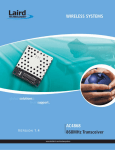
Notes:
www.e n e r g y f o c u s i n c .com
WaterLevV
™
Installation Manual
Model IGW 5000
This product has been tested to the requirements of CAN/CSA-C22.2 No. 61010-1, second
edition, including amendment 1, or a later version of the same standard incorporating the same
level of testing requirements.
( Cabled Model )
This product must be installed under the guidelines of the National Electric Code or the Canadian
Electric code.
Note: If used in a manner not specified by the manufacture, the protection provided by the
equipment may be impaired.
Pool and Spa Water Level
Monitoring System
Distributed by ENERGY FOCUS, INC.
32000 Aurora Road
Solon, OH 44139
1-800-327-7877
Manufactured by W at er Lev V Inc.
Montreal, Canada
Rev. 4 08042009
Unit Specifications
Thank you for purchasing the Industries newest and most
technologically advanced Pool / Spa water level monitoring
system on the market.
Your new Pool / Spa Water Level System is fully automatic.
The system incorporates several user alarms which indicate
both Water Level or flow issues and System monitoring such as
Low Battery monitoring and loss of water flow.
Please Read before Installation
Sensor Unit:
Power operation:
9 VDC Valve supply voltage
Operating Cycle:
Level Check every 1 hour
Operating Range:
40°F to 125°F / 5°C to 55°C
Model IGW-5000 Range:
75 ft / 23 meters of cable
Installation:
Adjustable height
Warranty:
1 Year
Valve control Unit:
Systems Contents:
Power Supply (Rain tight outdoor type):
120VAC 138mA / 9VDC 1A
rating Operating Cycle:
5 minute Valve on Time
Output Volume:
Approx. 32 Gallons / 120 Litres
Operating Temperature:
40°F to 125°F / 5°C to 55°C
Remove contents from shipping packaging and verify contents
are complete.
Inlet Fitting Type:
3/4” Male Garden Hose Fitting
Outlet Fitting Type:
Male 3/4” NPT
Before starting the installation verify that the pool is filled to the
desired level.
Water pressure:
15 – 100 PSI
System Alarms:
Low Battery
Sensor with 75ft cable, Sensor Mounting Bracket, Skimmer Lid
Bracket, Valve Control Unit with built in Check Valve, 2” x 2” x
¾” PVC “T” Fitting, ¾” Garden Hose Adapter, User’s Manual
and Installation Manual.
High Water
Please see Figure “A” for typical system configuration
No Flow / Possible Leak
Warranty:
1 Year
Maintenance:
If the system no longer maintains the water level, please check the following:
1.
Water Inlet screen may be blocked with dirt or debris.
Solution:
Shut off the water source and remove Inlet connection, then remove the
¾” – ¾” adapter. The Dirt screen is located in the Inlet port, remove, clean
and replace. Reconnect the water connection and turn on the water source.
* If Dirt Screen is not replaced damage to the valve may occur.
2.
Figure “A”
Lose of Power
Solution:
•
•
Verify that the Power Adapter is plugged and functioning
Power LED of the Valve Unit should be On
Control Unit LED definition as follows:
Sensor Installation
LED No. 1 Indicates Power On Status
Choose a location to install Sensor Bracket; some possible
locations are in the neck of the skimmer, behind the skimmer weir
or on any surface touching the water. Keep in mind to keep the
Sensor away from being hit or damaged from Childs play or
other objects.
LED No. 2 Indicates Data Received
LED No. 3 Indicates Valve activation
LED No. 4 Indicates Low Battery Alarm
( n/a on the IGW-5000 )
LED No. 5 Indicates High Level Alarm
( 4 Beeps every 6 minutes )
LED No. 6 Indicates Water Flow Error
( Warble Tone every 7 minutes )
You can attach the Sensor Bracket with ABS Pipe Glue or with
Stainless Steel screws supplied.
Install the Sensor in the Bracket and adjust Sensor
approximately 1/4” above Water level.
A Skimmer Lid Bracket is also supplied in the case that
the Sensor is to be placed attached to the Skimmer Lid.
Control Valve Reset Switch definition:
Press Reset Button for 1 second to silence Alarms.
Hold Reset Button for 3 seconds to Reset Alarms.
Hold Reset Button for 3 seconds to Reset Water Valve.
System Seasonal Power down procedure:
Disconnect the Valve Units power source or Power Supply
cable.
If you live in an area where Freezing is possible Disconnect,
Drain and or shut off the water source.
Figure “B”
Skimmer Lid Bracket
Figure “C”
Skimmer Bracket can be installed with ABS compatible
adhesives, such as ABS Pipe Cement, or Attach with Screws.
Sensor Cable Installation
Once the location of the Sensor has been determined you
will need to drill a ½” hole as near the top edge of skimmer
close above the Sensor.
Pass the Sensor wire through the Hole ( See Figure “D” )
System Functions
Sensor is in a Start-up test mode for the first 10 minutes
after Sensor is installed in the Sensor Bracket, this will
allow you to test the level by moving the Sensor unit up or down
on the bracket to test Valve activation. If further testing is
required simply remove sensor and re-insert back into the
bracket, this will restart the test mode.
( See Sensor LED definitions on the Last Page )
Low Water Level monitoring:
The WaterLevV System will automatically verify the Pool or
Spa’s water level every hour.
The system will automatically add water in 5 minute intervals
whenever a low level is detected.
High Water Level monitoring:
Figure “D”
Install a ½ PVC Electrical conduit between Skimmer and
Valve Unit Location. ( See Figure “E” )
If an extended High Water Level ( more than 12 hours ) is
detected the system will alert you, a Back Wash or drain may be
required to lower the water level.
If the High Level is minor, standard water dissipation over the
following days will automatically reset High Level Alarm and the
system will returns to normal status.
Low Battery Level detection:
( not available on the IGW-5000 )
Water Flow monitoring:
The system automatically monitors Water flow, If an extended
loss of water flow is detected a Flow Alarm will be triggered.
This alarm also can detect a leak in the Pool; an excessive
number of low Level demands may indicate a leak.
Figure “E”
With the help of a cable fish, gently pull the Sensor Cable
through the conduit.
Seal the Cable Hole in the Skimmer with Silicon
Sensor LED definitions as follows:
YELLOW indicates LOW LEVEL Detection
RED indicates HIGH LEVEL Detection
GREEN indicates Send Data
If additional testing time is required simply remove and replace
the Sensor back in its Bracket, this will restart the start-up
period.
Shut off the power to the Pool Pump and switch the Filter
control to Drain or Back Wash.
Locate the return line from the Pool pump to the Pool. Choose
a location on the return line to cut and install “T” fitting. ( See
Figure “F” )
Figure “F”
Glue “T” fitting with the ¾” Fitting pointing vertically upwards.
Let glue set for one to two minutes ( See Figure “G” )
Figure “J”
Apply Water source to verify there are no leeks.
Return Filter Control to normal position and turn on the Pool
Pump.
Installation is now complete.
Figure “G”
System Start-up
Sensor Unit has a built in Start-up mode which gives the
Installer time ( 10 min. ) to adjust the Sensor Level and visually
see LED’s display the Water Level Status.
Next apply 2 – 3 turns of plumber tape to the outlet of the
Valve unit.
Thread Valve Unit into the ¾” “T” fitting,
*
Tighten Valve by hand do not use Pliers or grips
*
Power Source and Sensor Connections
Water Source Connection
Remove the Blue Valve Cover, then remove the Cable Clip by
loosening the Phillips screw located on the outside of the Valve
Unit.
Remove the Clip and install the Power Supply Cable and
Sensor Cable. Insert Connectors with Cable pointing upwards
and then loop the cable downwards. ( See Figure “H” )
Replace Cable Clip and tighten Philip’s Screw to lock the Power
Cable in place.
Install Garden Hose adapter to Valve Unit Inlet.
Attach the short side of the Fitting to the Valve and the longer
side is to attach to your Water Source.
This connection is necessary to leave access the Water inlet
Screen Filter for future cleaning.
( See Figure “I” & “J” )
Figure “H”
If a permanent Water source is preferred use standard ¾” GHT
fitting to complete Inlet connection.
Figure “I”