1
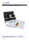
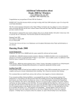
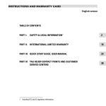
Moysinie Ver. 2.0.3
User Manual
Moysinie sl
CIF B84137009
C/Francisco Silvela 52 1º-A
28028 Madrid
www.moysinie.com
(+34) 91 151 63 13
[email protected]
Index
General ............................................................................................
Project Based Hierarchy ....................................................……………………
Zone input ........................................................................................
The zones’ drawing .........................................................................….
Zones import from AutoCAD.................................................................
Reinforcement Introduction .................................................................
Traditional Solution ............................................................................
Reinforcement area [mm2/m] ...........................................................…
Mesh Optimisation Parameters .............................................................
Mesh edit ..........................................................................................
Mesh Groups/Types storage ........................................……………………………
Bar Edit ............................................................ ...............................
New Mesh Type Creation ..............................................................………
Mesh Bending ....................................................................................
Clients Edit .......................................................................................
Printing Features ...............................................................................
Program Languages ...........................................................................
Diameter Setup .................................................................................
Additional Reinforcement ....................................................................
Printing out Additional Reinforcement ...................................................
Printing Out Mesh List ..............................................................………….
MeshBeam Module .............................................................................
New Beam Design ........................................................................…….
Long Bars introduction ............................................………………………………
Stirrups’ Distribution ..........................................................................
Non-rectangular Beam’s Section ..................................................………..
Creation of the AutoCAD Drawings ...............................................……….
Results exported to MS Excel ............................................……………………
3
6
6
6
7
12
12
13
14
15
16
16
16
16
18
18
19
19
20
24
25
26
28
30
32
35
39
41
2
Moysinie sl
CIF B84137009
C/Francisco Silvela 52 1º-A
28028 Madrid
www.moysinie.com
(+34) 91 151 63 13
[email protected]
General
Moysinie is software specialized in the steel reinforcement solutions for the
construction industry.
The program performs the calculations mutually with the automatic generations of
all interrelated drawings and tables, working out the following outcomes:
Optimal Mesh
The program is looking for the mesh, that will cover all zones (areas) with the
minimum of reinforcement steel. In other words, one mesh is to be chosen for all
the zones we have been optimising.
Evidently, presuming the same total number of zones, the result of a realisation of
more individual optimisations with less zones per process, is better concerning the
weight (is less), and poorer concerning the number of different types of meshes (is
greater). That because in principle, a different mesh will be chosen for each
different optimisation.
Therefore a distinct criteria will be chosen depending on the program user: e.g. in
case of a designer or a contractor, more independent optimisation processes will
be applied than if the user is a mesh producer.
Optimal Pre-defined Mesh
When the process of the mesh optimisation explained above is limited to the
previously defined mesh types of the project.
3
Moysinie sl
CIF B84137009
C/Francisco Silvela 52 1º-A
28028 Madrid
www.moysinie.com
(+34) 91 151 63 13
[email protected]
Additional Reinforcement
Possibility to introduce the bending schedule of the additional (loose) rebars for
each zone. Optionally, each bar can be drawn and marked on the zone layout
drawing.
Bent Mesh Based Elements
When some elements, such as
beams or columns, are to be
produced as a result of a mesh
bending.
4
Moysinie sl
CIF B84137009
C/Francisco Silvela 52 1º-A
28028 Madrid
www.moysinie.com
(+34) 91 151 63 13
[email protected]
Traditional Solution
The program calculates the weight of a traditional solution per zone, per direction,
and the total weight, generates bending schedules with the exact rebar location,
quantity, bar size, length, shape code, segment lengths and weight.
5
Moysinie sl
CIF B84137009
C/Francisco Silvela 52 1º-A
28028 Madrid
www.moysinie.com
(+34) 91 151 63 13
[email protected]
1. Project Based Hierarchy
All the calculations are associated to the Project and the results and drawings
are saved in the correspondent Project’s directory.
Any change of the project can be performed in any time.
After the project selection, pressing the button Project Edit, the widow of the
zones’ introduction will be opened, where the new zone can be added or
previously selected zone deleted.
From this window, pressing the Mesh & Traditional Solution button, the
program will proceed to the optimization process,
and pressing the Mesh Edit button will leave to the
pre-defined mesh types edition.
2. Zone input
The number of zones per project is not limited.
The zones’ introducing can be executed in any time - the new zone can be
added in the project by drawing, or importing from AutoCAD.
3. The zones’ drawing
The drawing of the zone is very simple and intuitive.
To draw the new zone press the button Draw Next Zone.
The new window will appear, to introduce the number of the
same zones (“1” by default) and the zone’s name (“Zone i”
by default).
6
Moysinie sl
CIF B84137009
C/Francisco Silvela 52 1º-A
28028 Madrid
www.moysinie.com
(+34) 91 151 63 13
[email protected]
The lines (zone’s limits) are orthogonal by default. Pressing the functional key
F8, the introducing is being changed from orthogonal to non-orthogonal and
vice verse.
During the zone drawing, when the mouse is being moving, the co-ordinates (in
meters) are being changing as integer numbers. However, the number (with
decimals) can be modified manually – first, press the TAB
key until the co-ordinate is selected (marked in blue), then
introduce the new value.
When the co-ordinate is correct, the line will be drawn by
pressing the ENTER key, or the Left Mouse button.
To undo the line drawing, press the Right Mouse button.
The zone drawing must be finished by CLOSING the polygon (zone’s border).
The last line that connects the last and the first point, should be drawn by
pressing simultaneously SHIFT key and Left Mouse button. So, when the last
point of the polygon (zone) is drawn, press SHIFT + Left Mouse button to draw
the last line, i.e., to close the polygon. After closing the zone (polygon), the
eventual hole in the zone can be drawn - the co-ordinates X and Y of a first
point are shown; by pressing the Left Mouse button, the line is starting to be
drawn. Again, the hole must be closed in the same way, pressing
simultaneously SHIFT and Left Mouse button.
To accept the drawing, press the button Drawing
Finished.
To delete the zone in any moment, press the Delete Zone button.
4. Zones import from AutoCAD
In any moment, any number of new zones can be imported from AutoCAD.
Between this and the next
green line, all the screens are
from the application AutoCad.
Zones are drawn or the existing
AutoCAD drawing is opened:
7
Moysinie sl
CIF B84137009
C/Francisco Silvela 52 1º-A
28028 Madrid
www.moysinie.com
(+34) 91 151 63 13
[email protected]
Important:
a) AutoCad drawing must contains only lines (not polylines, nor arcs, circles,
etc.). Obviously, every shape that comes in the original drawing, can be
approximated with lines. It is recommended to draw zones in a new layer
(e.g., we will call it MOYSINIE) over the original drawing, using only lines. At
the same time, we can exclude geometry details from the original drawing,
which are not important, such as small holes in the structure. When we
finish a drawing, we turn off all layers, except the one called MOYSINIE. Now
we have a drawing prepared for the application.
b) Co-ordinates should have positive values, and less then 1000(m).
c) Make sure that the zone(s) (and all holes if there are any) is/are closed
(every line is connected at both ends with the another line).
d) Check if lines that are very close to vertical or horizontal (90º and 270º, or
0º and 180º) are really vertical or horizontal; to be precise, assure that coordinates of both line points (X, or Y respectively), are equal. The easiest
way is to draw these lines using the AutoCad function key F8.
Zones that have been drawn should be written in the “log” file generated by
AutoCAD. Hereafter, this file will be called FichLog. All commands that follow will
be executed in AutoCAD.
Open FichLog for data entry. Type “LOGFILEMODE”, and introduce a value “1” (if it
is “0”, FichLog is closed, if it is “1”, FichLog is opened for the data entry):
Type a command “LIST”:
8
Moysinie sl
CIF B84137009
C/Francisco Silvela 52 1º-A
28028 Madrid
www.moysinie.com
(+34) 91 151 63 13
[email protected]
Now, AutoCAD will ask to select the zone – the message “Select objects:” will
appear:
Important: the command “LIST” must be entered before the selection of every
zone. To be precise, only one and entire zone is selected after the message
“Select objects:”. When all the lines of one zone are selected, press ENTER, and a
window with the zone’s co-ordinates will appear:
9
Moysinie sl
CIF B84137009
C/Francisco Silvela 52 1º-A
28028 Madrid
www.moysinie.com
(+34) 91 151 63 13
[email protected]
In the last text line the message “Press ENTER to continue” will appear, so
continue pressing ENTER until the word “Command:” appears:
Now, if there are more zones to be introduced, type “LIST” again, and follow the
same procedure.
When all zones are entered, close the FichLog by typing the command
“LOGFILEMODE” and entering the value “0”:
10
Moysinie sl
CIF B84137009
C/Francisco Silvela 52 1º-A
28028 Madrid
www.moysinie.com
(+34) 91 151 63 13
[email protected]
Finally, type the command “LOGFILENAME” and save (copy) the answer:
From here on, all the screens
are from the program
Moysinie.
Returning to the program Moysinie, to configure the
connection with AutoCAD, press the button AutoCAD
Settings. The text box will appear to introduce the name
(and the path) of the AutoCAD “log” file of the zone(s)
drawing. Paste the copied name in the box and press OK:
After AutoCAD setting, press the button Import Next
Zone(s) from AutoCAD. The new window will appear to
introduce the number of new zones to be imported from
AutoCAD, and afterwards, each zone will be shown. The
number of the same zones (“1” by default) and the zone name (“Zone i” by
default) must be confirmed, or introduced.
11
Moysinie sl
CIF B84137009
C/Francisco Silvela 52 1º-A
28028 Madrid
www.moysinie.com
(+34) 91 151 63 13
[email protected]
5. Reinforcement Introduction
Pressing the Mesh & Traditional Solution button in the Project Edit
window, the window of the reinforcement characteristics appears:
As the program calculates both mesh and traditional solutions, it is possible to
have two different types of reinforcements. This can be interesting in case we
want to substitute the traditional by a double mesh reinforcement, or if the
traditional and mesh reinforcement have different overlaps. In the example,
however, both traditional and mesh reinforcements are the same.
Moreover, it is possible to set up the standard bar length and the concrete cover.
By pressing the button Bar Size & Weight Setup, the bar diameters, weights and
bending diameters can be defined.
Different Reinforcements Types
After the bar sizes, spacing and overlapping of both directions are defined,
pressing the Save Reinforcement Type As... button, the reinforcement type
name should be introduced (e.g. Sup, Inf, ...). This is repeated as many times as
12
Moysinie sl
CIF B84137009
C/Francisco Silvela 52 1º-A
28028 Madrid
www.moysinie.com
(+34) 91 151 63 13
[email protected]
it is the number of different reinforcement types. The outputs are being stored in
the files named by the zone and reinforcement type (e.g. Zone 1-Sup, Zone 1Inf, Zone 2-Sup, ...).
To proceed to the optimization with the next reinforcement type (e.g. Inf), the
process of the current reinforcement type (Sup), should be terminated. This
means that the window with the mesh of the current optimization should be
opened (see 9. Mesh Edit). Pressing the Next Reinforc. Type button, starts the
optimization of the next reinforcement type (Inf).
One-Directional Mesh
If the reinforcement type corresponds with the 1D mesh of the direction “X”, mark
the corresponded boxes.
In such case, the overlapping in the direction “Y” disappears. The reinforcement
type should be saved as it was explained previously.
The number of different reinforcement types practically is not limited, so if it is the
case, the types of 1D and 2D meshes can be saved together.
6. Traditional Solution
Pressing the Traditional Solution button, the new window with the traditional
solution’s details will appear. The bending schedules can be checked and printed
out.
13
Moysinie sl
CIF B84137009
C/Francisco Silvela 52 1º-A
28028 Madrid
www.moysinie.com
(+34) 91 151 63 13
[email protected]
7. Reinforcement area [mm2/m]
When the optimization with pre-defined meshes is to be done, the zones
reinforcement area (ZRA) should be introduced in both directions (if omitted, will
be considered as 0, i.e. any mesh type will accomplish the target). In the
optimization process, the ZRA
will be compared with the
pre-defined meshes’
reinforcement areas (MRA),
and only if the MRA ≥ ZRA
(for each direction), the mesh
could be considered as a
possible solution.
The MRA (for each direction)
appear in the Mesh Properties
window (see 9. Mesh Edit):
14
Moysinie sl
CIF B84137009
C/Francisco Silvela 52 1º-A
28028 Madrid
www.moysinie.com
(+34) 91 151 63 13
[email protected]
8. Mesh Optimisation Parameters
When the Mesh Solution button is pressed, the following window appears:
If the bar sizes
and distances are
previously
introduced (see
5. Reinforcement
Introduction),
both Pre-defined
and Non-Predefined (No
Restraint) mesh
optimisation
process can be
executed, and if
the
reinforcement
areas have been
introduced (see
7. Reinforcement
area [mm2/m]),
only Pre-defined
mesh
optimisation can
be done.
If the No Restraint mesh is opted, the mesh length and width limits should be
entered. If not all zones are to be optimised (with the same mesh), select which
one are to be optimised together.
The last (edge) sheets could be cut to fit the zone edge, or “pushed” inside the
zone, and in that case no sheet cuts will be performed.
The Mesh Orientation in the selected zones layouts can be forced to the
horizontal or vertical direction. If the orientation is not forced (the 3rd option on
the screen), the program calculates the best mesh orientation for each zone.
If the Pre-defined mesh optimisation is opted, choose the Mesh Group from which
the meshes are to be chosen. If not all, choose Meshes to be examined.
15
Moysinie sl
CIF B84137009
C/Francisco Silvela 52 1º-A
28028 Madrid
www.moysinie.com
(+34) 91 151 63 13
[email protected]
9. Mesh edit
Pressing the Pre-defined Mesh Edit button,
window will be opened.
the mesh edit
Selecting the Mesh Group and Mesh Type (previously defined), the mesh drawing
appears:
Each bar can be modified separately (different diameter, length, position,
bending). It is necessary to mark the bar direction (Long Bar or Cross Bar), type
the Bar Number, and its properties will be shown, ready to be modified.
To create the Mesh Group, type the mesh group name, and press the button Add
below. Pressing the button Save/Add below the Mesh Type name, the displayed
mesh will be saved into the current Mesh Group.
16
Moysinie sl
CIF B84137009
C/Francisco Silvela 52 1º-A
28028 Madrid
www.moysinie.com
(+34) 91 151 63 13
[email protected]
a) Mesh Groups/Types storage
Every project has its own mesh groups and types. If it is necessary, by coping
all the files from the directory ...\Moysinie\Projects\Project XY\Mesh Type
to the directory
...\Moysinie\Projects\Project PQ\Mesh Type
the new project PQ will have the same mesh groups and types as the old
project XY.
b) Bar Edit
When the bar is selected, all three projections are shown painted in green.
c) New Mesh Type Creation
It is possible to enter a new
mesh type, by pressing the
button Draw New Mesh Type.
One bar in each direction will be
displayed. By coping and modifying them, the new mesh can be created.
d) Mesh Bending
The mesh can be bent in all four extremes, two times each one. The bending
can be realized in two ways:
d.1.)
“Bar-by-Bar Bending”. In the Bar Edition process where one by bar
is being selected, the values of the bar segment (length) to be bent
and the bending angle can be introduced/modified.
d.2.)
“All-Bars-in-Line Bending”. Choosing the direction (Long Bar or
Cross Wire) and the option 1st Bend in Line,
or 2nd Bend in Line, the corresponding text
boxes are opened to introduce the Length to
Bend and the Bending Angle. The illustration of
the Bend in Line is shown below:
Length B
d
2n
An
gle
t
1s
in
ne
nd
Be
in
Li
ne
th
ng
Le
1s
tA
ng
l
e
2n
d
nd
e
B
Li
A
"Left" for the Longitudinal Section
"Right" for the Longitudinal Section
"Bottom" for the Cross Section
"Top" for the Cross Section
17
Moysinie sl
CIF B84137009
C/Francisco Silvela 52 1º-A
28028 Madrid
www.moysinie.com
(+34) 91 151 63 13
[email protected]
It is obvious that it is necessary to do the 1st Bend in Line before the 2nd Bend
in Line. Moreover, if at least one bar is already bent once or twice on the same
side, the 1st Bend in Line on that side cannot be performed. Equally, if at least
one bar is already bent twice on the same side, the 2nd Bend in Line on that side
cannot be performed.
So, the easiest way to bend the mesh is to start with the plane mesh, bend it
using 1st Bend in Line, where (see the previous illustration),
Length to Bend = Length A + Length B.
Then, using 2nd Bend in Line bend it again, where
Length to Bend = Length B.
Afterwards, if it is necessary, bend some bars separately, using “Bar-by-Bar
Bending” as it is shown below:
Length B
2n
d
d
2n
nd
e
B
An
g le
1s
t
in
ne
i
L
nd
e
B
in
ne
i
L
18
Moysinie sl
CIF B84137009
C/Francisco Silvela 52 1º-A
28028 Madrid
www.moysinie.com
(+34) 91 151 63 13
[email protected]
10.
Clients Edit
Pressing the button Clients Edit the new window is opened,
and it is possible to add/remove/edit a client. In any stage,
when the Project is opened, clicking over
the Client’s name is possible to change or modify it. When the
New Project is being introducing, the Client’s name can be
searched, or
introduced
new one
(and later on modified), or
omitted (and later on
introduced).
11.
Printing Features
Program generate the Microsoft Excel sheet and print it out on any installed
printer. The printing can be done within any window (Mesh Placement, Mesh
Properties, Bending Schedule). However, if it is necessary to print more (or all)
project zones, and/or more or all mesh types, clicking the
Print Project button on the initial window, the Printing Out
window will be opened:
19
Moysinie sl
CIF B84137009
C/Francisco Silvela 52 1º-A
28028 Madrid
www.moysinie.com
(+34) 91 151 63 13
[email protected]
The header of a print out shows the Project and the Client’s information, and the
footer, the drawing and the Company’s details. The Company details, as a logo
image, named Logo.jpg should be placed in the directory …\Moysinie\Misc, where
from the program will call it.
12.
Program Languages
It is possible to change the program
the change, after choosing the language,
the program.
13.
language. To produce
it is necessary to restart
Diameter Setup
Pressing the Bar Size & Weight Setup
button, the
Diameter Setup window appears. Typing the bar diameter,
the weight and the bending diameter are automatically
calculated. However these values can be modified to any
number.
20
Moysinie sl
CIF B84137009
C/Francisco Silvela 52 1º-A
28028 Madrid
www.moysinie.com
(+34) 91 151 63 13
[email protected]
14.
Additional Reinforcement
Every zone can have a bending schedule of the additional reinforcement.
By choosing the zone to be edited, the zone drawing (with the additional
reinforcement layout if there is any) appears:
21
Moysinie sl
CIF B84137009
C/Francisco Silvela 52 1º-A
28028 Madrid
www.moysinie.com
(+34) 91 151 63 13
[email protected]
If a new bar is to be added, by clicking the button Add the Bar, the new window
is opened. We introduce the bar parameters (POS, quantity, diameter, shape,
segments and angles):
The Shape is a number of the bar segments (from 1 to 6). Segments are named A,
B, C, … F. The angles between segments are α, β, γ, δ and ε. During the segments
introduction, the bar drawing is being executing. Every segment has its own colour
(both number and drawing). It is possible to have automatically all angles = 90º
(as in the example). In any moment is possible to change any bar parameter.
When the bar introduction is finished, if the box Include the Bar in the
Reinforcement Plan is checked, the bar will be placed in the zone layout:
22
Moysinie sl
CIF B84137009
C/Francisco Silvela 52 1º-A
28028 Madrid
www.moysinie.com
(+34) 91 151 63 13
[email protected]
The new bar (POS 34) is green, and the co-ordinates X and
Y are shown. If the bar has to be rotated, click the right
mouse button, and the new box will appear:
If type 70, the bar will be rotated for 70 degrees. If the
correct rotation was 90, by
clicking the right mouse button
again, the total angle will be
shown (in this case 70). Now, type
20 (to complete 90).
When X, Y and angle are correct, click the left mouse button to accept the bar
position:
23
Moysinie sl
CIF B84137009
C/Francisco Silvela 52 1º-A
28028 Madrid
www.moysinie.com
(+34) 91 151 63 13
[email protected]
However, in any moment, bar characteristics and/or bar position can be modified.
Just click over the bar POS (for example POS 26),
and the Bar Window will be opened:
After the bar correction, press the Confirm Change button. If the box Include
the Bar in the Reinforcement Plan is unchecked, this position will not be
drawn.
Then again, in any moment clicking the Edit Bending Schedule
button (in ADDITIONAL REINFORCEMENT window), and checking
the box Include the Bar in the Reinforcement Plan , it will be
possible to place the bar into the zone drawing.
24
Moysinie sl
CIF B84137009
C/Francisco Silvela 52 1º-A
28028 Madrid
www.moysinie.com
(+34) 91 151 63 13
[email protected]
If the box Include Mesh Drawing is checked, the mesh placement will be shown:
15.
Printing out Additional Reinforcement
The additional reinforcement (AR) list and drawing
(with or without the Mesh layout included) can be
printed.
The AR list includes the bar characteristics as well as
its drawing:
25
Moysinie sl
CIF B84137009
C/Francisco Silvela 52 1º-A
28028 Madrid
www.moysinie.com
(+34) 91 151 63 13
[email protected]
16.
Printing Out Mesh List
The Project’s mesh lists can be printed out, too.
The list can be grouped by mesh type or not
(zone by zone).
In any case, to print out the mesh list, it is
necessary to generate (include) the mesh
drawing into the zone.
In the MESH PROPERTIES window (after the
optimization), it is necessary to click the Save
Mesh in Project button (see 8. Mesh edit):
The mesh list shows mesh characteristics:
NºL and NºC are the number of longitudinal and cross bars. ØL and ØC are
diameters, DL and DC are distances and mm2/mL and mm2/mC are the
reinforcement areas for respective direction.
In case when the diameters and distances are not equal, the average ones are
calculated as per:
Ø = √((∑Øi2)/n)
D = (∑ Di)/(n-1)
Where n is number of bars (of the respective direction).
26
Moysinie sl
CIF B84137009
C/Francisco Silvela 52 1º-A
28028 Madrid
www.moysinie.com
(+34) 91 151 63 13
[email protected]
17.
MeshBeam Module
This module is used when some elements, such as beams or columns, are to be
produced as a result of a mesh bending.
Zone selection:
As in the Additional Reinforcement, when the zone is selected (in this case,
Zone 1), its beams are shown (in this case, only one beam named B-1):
Fig. Beams Layout
Moysinie sl
CIF B84137009
C/Francisco Silvela 52 1º-A
28028 Madrid
www.moysinie.com
(+34) 91 151 63 13
[email protected]
27
Clicking over the beam name, the beam window will be opened:
To see the mesh, click the Mesh button and the mesh will be shown:
28
Moysinie sl
CIF B84137009
C/Francisco Silvela 52 1º-A
28028 Madrid
www.moysinie.com
(+34) 91 151 63 13
[email protected]
The mesh can be modified and saved as any other mesh. Also, it can be saved as
a beam and placed in the corresponding zone, by pressing the Save the Mesh &
Place the Beam button (placing the beam is equal as an additional bar placing the moving and rotating to the final position).
The lines of the bending are the black ones (in this case 5 of them), and the
distances are given on the right side of the drawing (in this case 120 + 289 + …).
a) New Beam Design
To introduce a new beam, click the Add Beam button (see the fig. Beams
Layout). The window will be opened:
After entering beam name, the working stirrup diameter should be introduced.
Automatically, the bending diameter is appearing. However, the bending diameter
can be altered. If the Rectangular Stirrups box is checked, only beam base,
height and hook are to be introduced:
29
Moysinie sl
CIF B84137009
C/Francisco Silvela 52 1º-A
28028 Madrid
www.moysinie.com
(+34) 91 151 63 13
[email protected]
The hook angle (135º) is shown automatically. It is the same as in the previously
introduced beam. Surely, it can be modified. Checking the Different Colors box,
the stirrup segments will be colored differently, checking the Dimensions box, the
stirrup’s dimensions will be shown:
30
Moysinie sl
CIF B84137009
C/Francisco Silvela 52 1º-A
28028 Madrid
www.moysinie.com
(+34) 91 151 63 13
[email protected]
b) Long Bars introduction
b-1) Stirrup’s Segments Order
To proceed with the long bars, the stirrup’s segments order will be
explained. This stirrup consists of 11 segments (6 straight segments, and
5 curved segments between 2 straight ones). The segments’ order is the
order of bending, displayed clicking over the Segment Numbers box:
When the stirrup’s segment is introduced (in this case, number between 1
and 11), the drawing of the corresponding part is highlighted.
b-2) Long Bar Position
The long bar can be placed on any straight segment’s part, or in the
center of the curved segment.
If e.g., the 7th stirrup’s segment is selected, by introducing Ø20 and
distance from bending=0, the bar will be shown as above. The distance
from bending for each straight segment is a distance from the previous
curved segment. In this case, it is a distance from a curved segment 6 on
the right side. The Segment’s Length is shown: 144mm (=200-40-2xØ8),
so the possible long bar position from the bending is between 0 and
144mm. Pressing the Save Bar button, the bar will be saved.
31
Moysinie sl
CIF B84137009
C/Francisco Silvela 52 1º-A
28028 Madrid
www.moysinie.com
(+34) 91 151 63 13
[email protected]
The bar will be colored red and the diameter will be shown.
b-3) Long Bars Introduction by Typing
To proceed introducing long bars on the same segment, type the new
diameter (e.g. 16), and the distance from the previous bar (70):
(Note: only the 1st long bar of each segment must be introduced typing
the distance from the bending, and not from the previous bar).
b-4) Change a Stirrup’s Side
By clicking the corresponding box, the selected bar will change the
stirrup’s side:
b-5) Long Bars Introduction with Mouse
To select the bar, click the left mouse button over the bar diameter of any
bar (segment will be detected automatically), and move the bar to the
desired direction. The distance from the clicked bar (56) is shown:
32
Moysinie sl
CIF B84137009
C/Francisco Silvela 52 1º-A
28028 Madrid
www.moysinie.com
(+34) 91 151 63 13
[email protected]
If the diameter is to be changed, click the right mouse button, and the
diameter text box will appear:
Type the (new) diameter and press the ENTER to continue.
- To save the bar, press the left mouse button,
- to unselect the bar, press the ESC button,
- to delete some previously introduced bar, first select it and then press
the DEL button.
All these operations can be done by typing at the left side of the window:
introduce the desired bar number, and then press corresponding (e.g.
Delete Bar) button.
Note: long bars can be introduced with the mouse only if the box
Dimensions is checked:
c) Stirrups’ Distribution
After the beam section is finished (e.g. 2Ø20 bottom layer, 2Ø16 upper layer),
the beam length (5000mm) is introduced, and the drawing is shown:
33
Moysinie sl
CIF B84137009
C/Francisco Silvela 52 1º-A
28028 Madrid
www.moysinie.com
(+34) 91 151 63 13
[email protected]
In the example, the first stirrups will be 5 Ø8/100:
The stirrups will be shown green. If it is correct, press Save Stirrups button.
The stirrups will be colored blue and the distances and diameters will be shown:
The same process proceeds any number of times (every stirrup can be
different, on the different distance from the previous one). Repeating the above
process, the stirrups’ distribution will be as following:
To delete a stirrup, select it by typing its number (e.g. 11). It will be selected
(colored green). If it should be deleted, press the Delete Stirrup button, and
finally the beam will be as per below:
To see the generated mesh, press the Mesh button, and it will be shown:
34
Moysinie sl
CIF B84137009
C/Francisco Silvela 52 1º-A
28028 Madrid
www.moysinie.com
(+34) 91 151 63 13
[email protected]
If it is necessary, the mesh can be modified, and when it is finished, by
pressing the Save the Mesh & Place the Beam button, the layout window is
opened, and the beam can be placed. In the example, the beam B-2 will be
placed (and rotated for 30º):
35
Moysinie sl
CIF B84137009
C/Francisco Silvela 52 1º-A
28028 Madrid
www.moysinie.com
(+34) 91 151 63 13
[email protected]
d) Non-rectangular Beam’s Section
The beam’s section can have any form. If it is not rectangular, the check box
should be unmarked:
For every stirrup’s segment, introduce the angle of bending and the segment
length. Evidently, the angle for the first segment is not the angle of bending,
but the angle of the rotation (position).
Starting with angle=90 and segment=300, the first stirrup’s segment will be
drawn:
36
Moysinie sl
CIF B84137009
C/Francisco Silvela 52 1º-A
28028 Madrid
www.moysinie.com
(+34) 91 151 63 13
[email protected]
Proceeding with angle/segment = (-135/300; 180/200; -90/100; -45/150;
-135/150), the “beam” section will be drawn:
The long bars definition is already shown in the rectangular beam example. So,
after the long bars and the stirrups’ definition, the beam will be as per below:
37
Moysinie sl
CIF B84137009
C/Francisco Silvela 52 1º-A
28028 Madrid
www.moysinie.com
(+34) 91 151 63 13
[email protected]
Finally, the mesh drawing is designed:
38
Moysinie sl
CIF B84137009
C/Francisco Silvela 52 1º-A
28028 Madrid
www.moysinie.com
(+34) 91 151 63 13
[email protected]
18.
Creation of the AutoCAD Drawings
Moysinie creates the AutoCAD drawings (dxf files) of the mesh placement for all
the optimized zones, and saves them in the correspondent project directory:
Click over the desired zone, to open the AutoCAD drawing.
Click the Zoom Extents button of AutoCAD, and the zone will appear:
39
Moysinie sl
CIF B84137009
C/Francisco Silvela 52 1º-A
28028 Madrid
www.moysinie.com
(+34) 91 151 63 13
[email protected]
Moysinie creates the AutoCAD drawings of the saved mesh types, too. If the mesh
has been saved within the Mesh Group (see 9. Mesh Edit), the file dxf will have the
name such as GroupName-TypeName.dxf. If the mesh has been saved as a result
of the optimization process, it will be saved without the group name.
40
Moysinie sl
CIF B84137009
C/Francisco Silvela 52 1º-A
28028 Madrid
www.moysinie.com
(+34) 91 151 63 13
[email protected]
19.
Results exported to MS Excel
All the tables and drawings can be exported to Microsoft Excel permitting the
personal appearance of the outputs.
41
Moysinie sl
CIF B84137009
C/Francisco Silvela 52 1º-A
28028 Madrid
www.moysinie.com
(+34) 91 151 63 13
[email protected]