1
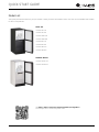
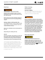
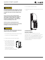
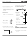
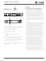
QUICK START GUIDE
1000 Series
•
CLR1215
•
115 V / 60 Hz
QUICK START GUIDE
u-line.com
WELCOME TO U-LINE
Congratulations on your U-Line purchase. Your product comes from a company with over five decades and three generations
of premium modular ice making, refrigeration, and wine preservation experience. U-Line continues to be the American
leader, delivering versatility and flexibility for multiple applications including residential, light commercial, outdoor and marine
use. U-Line’s complete product collection includes modular Wine Captain® Models, Beverage Centers, Clear Ice Machines,
Crescent Ice Makers, Glass & Solid Door Refrigerators, Drawer Models, Freezers, and Combo® Models.
U-Line has captivated those with an appreciation for the finer things with exceptional functionality, style, inspired innovations
and attention to even the smallest details. We are known and respected for our unwavering dedication to product design,
quality and selection. U-Line is headquartered in Milwaukee, Wisconsin with a west coast office located in Laguna Beach,
California and European support in Dublin, Ireland. U-Line has shipped product to five continents for over two decades and is
proud to have the opportunity to ship to you.
PRODUCT INFORMATION
Looking for additional information on your product? User Guides, Quick Reference Guides, CAD Drawings, Compliance
Documentation, and Product Warranty information are all available for reference and download at u-line.com under
Documentation.
PROPERTY DAMAGE / INJURY CONCERNS
In the unlikely event property damage or personal injury is suspected related to a U-Line product, please take the following
steps:
1. U-Line Customer Care must be contacted immediately at +1.800.779.2547.
2. Service or repairs performed on the unit without prior written approval from U-Line is not permitted. If the unit has been
altered or repaired in the field without prior written approval from U-Line, claims will not be eligible.
SERVICE INFORMATION
Answers to Customer Frequently Asked Questions are available at u-line.com under Customer Care or you may contact our
Customer Care group directly, contact information below.
GENERAL INQUIRIES
SERVICE & PARTS ASSISTANCE
U-Line Corporation
Monday - Friday 8:00 am to 5:30 pm CST
8900 N. 55th Street
T: +1.800.779.2547
Milwaukee, Wisconsin 53223 USA
F: +1.414.354.5696
Monday - Friday 8:00 am to 4:30 pm CST
Service Email: [email protected]
T: +1.414.354.0300
Parts Email: [email protected]
F: +1.414.354.7905
Email: [email protected]
u-line.com
CONNECT WITH US
Designed, engineered and assembled in WI, USA
QUICK START GUIDE
Contents
1
Model List
2
Safety and Warning
2
Environmental Requirements
3
Electrical
3
Water Hookup
6
Drain
8
Door Swing
8
General Installation
9
Integrated Panel Installation
11
Control Operation
11
First Use
11
Ice
13
Sabbath Mode
13
Warranty
u-line.com
QUICK START GUIDE
u-line.com
Model List
This guide provides the basics to get you started. Looking for more information? Visit u-line.com to view detailed User Guides
for all U-Line products.
Clear Ice
U-CLR1215S-00A
U-CLR1215S-40A
U-CLR1215INT-00A
U-CLR1215INT-40A
U-CLR1215B-00A
U-CLR1215B-40A
U-CLR1215W-00A
U-CLR1215W-40A
Outdoor Series
U-CLR1212SOD-00A
U-CLR1212SOD-40A
Visit http://www.u-line.com/product-literature/userguides or
scan this QR code to view all user guides online.
1
QUICK START GUIDE
u-line.com
Safety and Warning
This unit is designed to operate between 50°F (10°C) and
NOTICE
the unit’s ability to reach low temperatures and/or reduce
100°F (38°C). Higher ambient temperatures may reduce
ice production on applicable models.
Please read all instructions before installing,
operating, or servicing the appliance.
For best performance, keep the unit out of direct sunlight
and away from heat generating equipment.
Use this appliance for its intended purpose only and follow
these general precautions with those listed throughout this
guide:
In climates where high humidity and dew points are
present, condensation may appear on outside surfaces.
This is considered normal. The condensation will
SAFETY ALERT DEFINITIONS
evaporate when the humidity drops.
Throughout this guide are safety items labeled with a
Danger, Warning or Caution based on the risk type:
! CAUTION
! DANGER
Damages caused by ambient temperatures of
40°F (4°C) or below are not covered by the
Danger means that failure to follow this safety
warranty.
statement will result in severe personal injury or
death.
OUTDOOR UNITS
This unit is designed to operate between 50°F (10°C) and
100°F (38°C). Higher ambient temperatures may reduce
! WARNING
the unit’s ability to reach low temperatures and/or reduce
ice production on applicable models.
Warning means that failure to follow this safety
statement could result in serious personal injury
or death.
For best performance, keep the unit out of direct sunlight
and away from heat generating equipment.
! CAUTION
In climates where high humidity and dew points are
present, condensation may appear on outside surfaces.
Caution means that failure to follow this safety
This is considered normal. The condensation will
statement may result in minor or moderate
evaporate when the humidity drops.
personal injury, property or equipment damage.
! CAUTION
Environmental Requirements
Damages caused by ambient temperatures of
115 V UNITS
40°F (4°C) or below are not covered by the
This model is intended for indoor/interior applications only
warranty.
and is not to be used in installations that are open/
exposed to natural elements.
2
QUICK START GUIDE
u-line.com
Electrical
Water Hookup
INDOOR MODELS
! WARNING
PREPARE PLUMBING
Please use the braided stainless steel water supply line
SHOCK HAZARD — Electrical Grounding
which comes attached. The water line is fitted with a
Required. Never attempt to repair or perform
standard 1/4" (6.35 mm) compression fitting.
maintenance on the unit until the electricity has
been disconnected.
! WARNING
Never remove the round grounding prong from
the plug and never use a two-prong grounding
Prior to installation, determine if this product
adapter.
contains a gravity style drain or factory installed
drain pump. Products without a drain pump may
Altering, cutting or removing power cord,
only use a gravity style drain. Failure to connect
removing power plug, or direct wiring can cause
water supply or drain line connections properly
serious injury, fire, loss of property and/or life,
may result in water leakage, personal injury,
and will void the warranty.
and/or property damage. Disconnect power and
turn off water to the unit before attempting to
alter these connections. These connections are
Never use an extension cord to connect power to
the responsibility of the owner and must be
the unit.
connected per local plumbing code. If you are
uncertain of how to safely and properly install
Always keep your working area dry.
this product, contact a licensed plumber.
NOTICE
Water Supply Connection
Electrical installation must observe all state and
! CAUTION
local codes. This unit requires connection to a
grounded (three-prong), polarized receptacle
Review, obey, and understand the local
that has been placed by a qualified electrician.
plumbing codes before you install your unit.
Connect to the cold water supply. The water
The unit requires a grounded and polarized 115 VAC,
pressure should be between 20 and 120 psi (138
60 Hz, 15A power supply (normal household current). An
and 827 kPa). The water line MUST have a shut-
individual, properly grounded branch circuit or circuit
off valve on the supply line.
breaker is recommended. A GFCI (ground fault circuit
interrupter) is usually not required for fixed location
appliances and is not recommended for your unit because
it could be prone to nuisance tripping. However, be sure
to consult your local codes.
3
QUICK START GUIDE
u-line.com
4. Turn on water and check for leaks.
! CAUTION
5. Route water supply line in cable clamp and secure with
Do not use any plastic water supply line. The line
screw.
is under pressure at all times. Plastic may crack
or rupture with age and cause damage to your
home.
Do not use tape or joint compound when
attaching a braided flexible water supply line
that includes a rubber gasket. The gasket
provides an adequate seal – other materials
could cause blockage of the valve.
Failure to follow recommendations and
instructions may result in damage and/or harm,
flooding or void the product warranty.
! CAUTION
Turn off water supply and disconnect electrical
OUTDOOR MODELS
supply to unit prior to installation.
PREPARE PLUMBING
The water valve uses a standard 1/4" (6.35 mm)
1. Turn off water supply and disconnect electrical supply
compression fitting. U-Line recommends using accessory
to product prior to attempting installation.
water hook up kit – part # WATERHOOKUP. The kit
includes a 10' (3 m) braided flexible water supply line and
a brass hose fitting. When using a 1/4" (6.35 mm) O.D.
2. Locate the desired cold water supply location.
soft copper supply line use the brass nut and sleeve
included with the unit.
3. Locate braided stainless steel
water supply line and connect
to your cold water supply. The
water line should be looped into
2 coils. This will allow the unit
to be removed for cleaning and
servicing. However, make
certain that the tubing is not
pinched or damaged during installation.
4
QUICK START GUIDE
u-line.com
provides an adequate seal – other materials
! WARNING
could cause blockage of the valve.
Prior to installation, determine if this product
Failure to follow recommendations and
contains a gravity style drain or factory installed
instructions may result in damage and/or harm,
drain pump. Products without a drain pump may
flooding or void the product warranty.
only use a gravity style drain. Failure to connect
water supply or drain line connections properly
may result in water leakage, personal injury,
! CAUTION
and/or property damage. Disconnect power and
turn off water to the unit before attempting to
alter these connections. These connections are
Turn off water supply and disconnect electrical
the responsibility of the owner and must be
supply to unit prior to installation.
connected per local plumbing code. If you are
uncertain of how to safely and properly install
Use caution when handling back panel. The
this product, contact a licensed plumber.
edges could be sharp.
Water Supply Connection
1. Turn off water supply and disconnect electrical supply
to product prior to attempting installation.
! WARNING
2. Remove the grille/access panel in the front and the
Connect to potable water supply only.
back panel.
3. Locate water
! CAUTION
valve in the front
of the unit and
Review, obey, and understand the local
thread water
plumbing codes before you install your unit.
supply line
Connect to the cold water supply. The water
through.
pressure should be between 20 and 120 psi (138
and 827 kPa). The water line MUST have a shutoff valve on the supply line.
NOTICE
Route the water
supply line
! CAUTION
through the unit
so it does not come into contact with any
Do not use any plastic water supply line. The line
internal components other than the solenoid
is under pressure at all times. Plastic may crack
valve. Normal operation creates some vibration.
or rupture with age and cause damage to your
A water supply line contacting an internal
home.
component or cabinet wall can cause excessive
noise during operation or damage to the line.
Do not use tape or joint compound when
attaching a braided flexible water supply line
that includes a rubber gasket. The gasket
5
QUICK START GUIDE
u-line.com
Drain
4. On the back panel,
break away filler feature
in bushing with flat
Model numbers including “-00” or “-07” do not include a
screwdriver.
factory installed drain pump.
Model numbers including “-40” or “-47” include a factory
Remove
ZLWKɠDW
screwdriver
installed drain pump.
DRAIN CONNECTION
5. Thread water line
through back panel hole
! CAUTION
(with bushing).
If your U-Line unit did not come with a factory
installed drain pump you must use a gravity
style drain connection. For assistance in
determining if your unit has a pump please
contact U-Line. The floor drain must be large
6. Turn on water supply and check for leaks.
enough to accommodate drainage from all
attached drains. Follow these guidelines when
installing drain lines to prevent water from
7. Reinstall back panel and grille/front access panel.
flowing back into the ice maker storage bin and/
or potentially flowing onto the floor, which may
8. Install retaining clip.
result in personal injury or property damage.
NOTICE
Drain can NOT be located directly below the unit.
Unit has a solid base that will not allow the unit
to drain below itself.
There is a possibility that hose connections may
have loosened during shipment.
Verify all connections and fittings are free from
leaks.
6
QUICK START GUIDE
u-line.com
FACTORY INSTALLED DRAIN PUMP
GRAVITY DRAIN
If your drain line will run up to a stand pipe, disposal or
spigot assembly, or does not otherwise meet the
requirements for a gravity drain, you may have ordered a
Normal
Proper Drain
pre-installed U-Line P60 drain pump.
If you need to install a P60 drain pump into your unit, see
With Trap
Poor Drainage, Water Will Back Up
DRAIN PUMP section in the User Manual.
See below for typical installations requiring a drain pump.
With Trap and Vent
Proper Drain
Stand Pipe
P60 Pump Required
A gravity drain may be used if:
Drain line has at least a 1" drop per 48" (approximately
2 cm drop per 100 cm) of run.
Waste
Drain line does not create traps and is vented per local
6KXW2ɞ
Valve
code.
Hot
Water
1. Cut the pre-installed drain tube to length.
2. Connect to your local plumbing per the local code.
Cold
Water
Waste
Disposal Assembly
P60 Pump Required
3. If necessary, insulate drain line to prevent
Air Gap
(Optional Hook-Up)
condensation.
! CAUTION
Waste
Failure to connect water supply or drain line
connections properly can result in personal
Hot
Water
injury and property damage. Gravity drain
connections must be routed downward from the
Cold
Water
6KXW2ɞ
Valve
rest of the unit at the rate of 1/4" per foot (1 cm
per 50 cm).
7
QUICK START GUIDE
u-line.com
General Installation
Y-Branch Tailpiece
P60 Pump Required
Air Gap
(Optional Hook-Up)
LEVELING INFORMATION
1. Use a level to
confirm the unit is
level. Level should
Waste
be placed along top
6KXW2ɞ
Valve
edge and side edge
as shown.
Cold
Water
Hot
Water
1
NOTICE
The maximum lift for the P60 drain pump is
10 feet. This must be done as close to the rear of
the unit as possible.
2. If the unit is not level, adjust the legs on the corners of
the unit as necessary.
Door Swing
Wall
Wall
1/4" Min.
(6 mm)
2-1/8" Min.
(54 mm)
Turn to Adjust
3. Confirm the unit is level after each adjustment and
repeat the previous steps until the unit is level.
90°
Door Swing
90°
Door Swing
INSTALLATION TIP
If the room floor is higher than the floor in the cutout
opening, adjust the rear legs to achieve a total unit rear
d
l
l
l
k
d
Units have a zero clearance for the door to open 90°,
h
height of 1/8" (3 mm) less than the opening’s rear height.
Shorten the unit height in the front by adjusting the front
when installed adjacent to cabinets.
legs. This allows the unit to be gently tipped into the
opening. Readjust the front legs to level the unit after it is
Stainless Steel and black and white models require 2-1/8"
correctly positioned in the opening.
(54 mm) door clearance to accommodate the handle if
installed next to a wall.
Integrated models require 1/4" (6 mm) clearance if
installed next to a wall. Allow for additional space for any
knobs or pulls installed on the integrated panel/frame.
8
QUICK START GUIDE
u-line.com
INSTALLATION
NOTICE
1. Plug in the power/electrical cord.
Due to differences in floor construction or
surrounding cabinetry, the panel may not sit
flush with the top of the door/drawer.
2. Gently push the unit into position. Be careful not to
entangle the cord or water and drain lines.
Panel
Door
3. Re-check the leveling, from front to back and side to
side. Make any necessary adjustments. The unit’s top
surface should be approximately 1/8" (3 mm) below
the countertop.
4. Install the anti-tip bracket.
6. Secure integrated
panel to door/drawer
Bar
Clamp
using clamps. A
5. Remove interior packing material and wipe out the
robust tape may also
inside of the unit with a clean, water-dampened cloth.
be used. U-Line
recommends the use
of bar clamps to
Integrated Panel Installation
secure the panel to
1. Fully open door/drawer.
using tape, be
the door/drawer. If
Door/Drawer
Wood
Panel
certain the tape will
not damage panel
2. Starting at corner, pull
finish upon removal.
gasket away from door/
drawer.
7. Using a 7/64" (3 mm)
drill bit, drill 6 pilot
3. Continue to pull gasket
Bar
Clamp
holes into the wood
free from gasket channel.
panel 1/2" (12 mm)
deep using the holes in the door/drawer frame as a
4. Upon removal, lay gasket down on a flat surface.
guide.
5. The panel should be aligned with the outside edge
NOTICE
(opposite the hinge) and high enough to align with the
It is important to ensure that all drilled holes are
highest point in the door/drawer.
drilled to the correct depth in order to avoid
splits in the wood when hardwood is installed.
Align Top Of Panel With Highest Point Of Door/Drawer
8. Locate 6 of the #6x 1-1/4" (32 mm) screws provided
with your unit.
Align Panel
Against
Door/Drawer
Edge First
9
QUICK START GUIDE
u-line.com
9. Using a Phillips screwdriver, place one screw into each
of the 6 pilot holes and screw down. Do not overtighten
screws.
10.Be sure the screws force their way past the opening on
the gasket channel and sit flush against the bottom of
the channel.
Integrated Panel
Integrated Panel
11.Remove clamps from door/drawer.
NOTICE
If panel requires additional adjustment after
removing clamps, slightly loosen each screw and
adjust panel as necessary. Tighten screws upon
completion.
12.Starting at the corners, re-install the gasket into the
gasket channel in the frame. Make sure the gasket is
fully seated. This may take some force.
10
QUICK START GUIDE
u-line.com
Control Operation
Alert
Light Power Clean LED
Up Down
CONTROL FUNCTION GUIDE
FUNCTION
COMMAND
DISPLAY/OPTIONS
ON/OFF
Press
Unit will immediately turn ON or OFF.
Adjust ice thickness
See “Ice” section
View temperature in unit
Press
Toggle between F/C
Hold
Sabbath Mode
See “Sabbath Mode” section
and release
and
and
The display will flash and then toggle from set point
together and release
to temperature in unit.
for five seconds
The display will beep and display unit temperature.
Silent Mode (ice
production suspended for
Hold
and
Hold
for five seconds
Display will show “OFF”.
3 hours)
Clean Mode
First Use
Ice
All U-Line controls are preset at the factory. Initial startup
ICE CUBE THICKNESS ADJUSTMENT
requires no adjustments.
Interval - As Required
NOTICE
NOTICE
Ice thickness adjustment should only be made
U-Line recommends discarding the ice produced
one increment at a time. Allow ice maker
during the first two to three hours of operation
production to stabilize for 24 hours before
to avoid possible dirt or scale that may dislodge
rechecking ice thickness.
from the water line.
The ice cube thickness is factory set for best overall
When plugged in, the unit will begin operating under the
performance. The factory setting is designed to maintain
factory default settings. If the unit was turned off during
an ice bridge of approximately 1/16" to 1/8" (1.6 mm to
installation, simply press
3.2 mm) under normal conditions, resulting in a dimple of
and the unit will immediately
switch on. To turn the unit off, press
approximately 1/4" to 1/2" (6.4 mm to 12.7 mm) in
and hold for 5
seconds and release.
11
QUICK START GUIDE
u-line.com
depth. A fuller cube with less of a dimple results in a
Ice thickness adjustments are made using the control
thicker ice bridge. As the ice bridge becomes thicker, the
panel as follows:
tendency for the cubes to stay together as a slab
increases. A bridge thicker than 1/8" (3.2 mm) may cause
1. To enter the thickness adjustment mode:
cubes to overfill the ice bucket.
• Press and hold
for 5 seconds.
• The display will switch to “0” to confirm the
thickness adjustment mode has been selected.
DIMPLES
The factory setting is “0,” and the total range of
adjustment is -5 to +5 (ideal range is -1 to +1). Use
raise the setting and thicken the ice bridge, or
ICE BRIDGE
to
to lower
the setting to thin the ice bridge.
Ice Bridge and Dimples
Ice cubes in any given batch will vary, so it is necessary
to choose cubes from the sample area for comparison
when making adjustments.
Cube Types
1/4" TO 1/2"
(6.4 mm to 12.7 mm)
DIMPLE
1/16" TO 1/8"
(1.6 mm to 3.2 mm)
ICE BRIDGE
THIN BRIDGE
DEEP DIMPLE
THICK BRIDGE
LITTLE OR
NO DIMPLE
12
QUICK START GUIDE
u-line.com
Warranty
L
U-LINE CORPORATION LIMITED WARRANTY
Sabbath Mode
1. U-Line Corporation (“U-Line”) warrants each U-Line
product to be free from defects in materials and
1
2
3
4
5
6
workmanship for a period of one year (two years on
Modular 3000 Series) from the date of purchase.
U-Line further warrants the sealed system (consisting
of the compressor, condenser, evaporator, hot gas
bypass valve, dryer, and connecting tube) in each
U-Line product to be free from defects in materials and
Up
workmanship for a period of five years from the date of
Select
purchase.
2. During the initial one year warranty period (two years
on Modular 3000 Series) for all U-Line products U-Line
Down
shall: (1) repair any product or replace any part of a
product; and (2) for all Marine, RV, and Domestic
U-Line Clear Ice Machine models are Star-K certified and
U-Line products sold and serviced in the United States
can be used during the Sabbath. View a full list of Star-K
(including Alaska and Hawaii) and Canada, U-Line
certified U-Line units at www.star-k.org.
shall be responsible for the labor costs performed by a
U-Line authorized service company, incurred in
connection with the replacement of any defective part.
To prepare the unit for the Sabbath:
During years two through five of the warranty period
for the sealed system, U-Line shall: (1) at U-Line’s
1. Press
and hold the until the unit turns off.
option repair or replace any part of the sealed system;
and (2) for all Marine, RV, and Domestic U-Line
products sold and serviced in the United States
2. No new ice will form when the unit is off, but previously
(including Alaska and Hawaii) and Canada, U-Line shall
made ice will still be accessible/present for over 24
be responsible for the labor costs incurred in
hours. Pump equipped models will continue to remove
connection with the replacement of any defective part
water as needed even if the unit is off.
of the sealed system. All other charges, including
transportation charges for replacements under this
Sabbath Mode remains active until
is pressed again
warranty and labor costs not specifically covered by
and the unit turns on.
this warranty, shall be the responsibility of the
purchaser. This warranty extends only to the original
purchaser of the U-Line product. The Product
Registration Card included with the product should be
promptly completed by you and mailed back to U-Line,
or you can register on-line at www.u-lineservice.com.
13
QUICK START GUIDE
u-line.com
water shall also cause this warranty to be void,
3. The warranty listed above does not apply to floor
display models. The warranty for these models shall
including flooding of the area in proximity of the unit
be 30 days from the date of retail purchase and only if
greater than 1/8" deep in water, hurricanes, splashing
U-Line’s Product Registration Card included with the
of pool water, or directing a spray from a hose or
unit is completed and mailed back or electronically
similar device into and around the unit.
submitted to U-Line. This 30 day warranty does not
apply to cosmetic damages. A proof of purchase may
7. If a product defect is discovered during the applicable
be required.
warranty period, you must promptly notify either
U-Line at 8900 N. 55th Street, Milwaukee, Wisconsin
53223 USA or at +1.800.779.2547 or the dealer from
4. The following conditions are excluded from this limited
warranty: use of cleaners other than the recommended
whom you purchased the product. In no event shall
stainless steel cleaners and U-Line Clear Ice Maker
such notification be received later than 30 days after
cleaner; installation charges; damages caused by
the expiration of the applicable warranty period. U-Line
disasters or acts of God, such as fire, floods, wind, and
may require that defective parts be returned, at your
lightning; damages incurred or resulting from shipping,
expense, to U-Line’s factory in Milwaukee, Wisconsin,
improper installation, unauthorized modification, or
for inspection. Any action by you for breach of
misuse/abuse of the product; customer education
warranty must be commenced within one year after
calls; food loss and spoilage; door and water level
the applicable warranty period.
adjustments (except during the first 30 days from the
date of installation); defrosting the product; adjusting
8. THIS LIMITED WARRANTY IS IN LIEU OF ANY AND ALL
the controls; door reversal; and cleaning the
OTHER WARRANTIES, EXPRESS OR IMPLIED,
condenser.
INCLUDING ANY IMPLIED WARRANTY OF
MERCHANTABILITY OR IMPLIED WARRANTY OF
FITNESS FOR A PARTICULAR PURPOSE, ALL OF WHICH
5. U-Line products are designed to operate in ambient
ARE DISCLAIMED. U-Line’s sole liability, and your
temperatures between 50°F and 100°F unless
exclusive remedy, under this warranty is set forth in
otherwise noted in the product manual. Exposure to
the paragraphs above. U-Line shall have no liability
temperatures outside this range may cause
whatsoever for any incidental, consequential, or
degradation of performance and issues, such as lower
special damages arising from the sale, use, or
ice production or spoiled contents, that are not
installation of the product or from any other cause
covered under the terms of this warranty as a result of
whatsoever, whether based on warranty (express or
that exposure. U-Line product may not be subjected to
implied) or otherwise based on contract, tort, or any
temperatures below 40°F without following the
other theory of liability.
winterization and vacation shutdown procedures in the
user guide.
Some states do not allow limitations on how long an
implied warranty lasts or the exclusion or limitation of
6. U-Line’s Outdoor Limited Warranty, set forth in this
incidental or consequential damages, so the above
Paragraph 6 shall apply to U-Line models deemed
limitations may not apply to you. This warranty gives you
suitable for outdoor use by Underwriters Laboratory
specific legal rights, and you may also have other rights
(“UL”) as noted in the U-Line Product Catalog, U-Line’s
which vary from state to state.
website, and/or on the serial tag located inside the
product.
Warranty 6/2014 Rev.G
A. Outdoor product may come into contact with rain by
virtue of outdoor use. Exposure to other sources of
Copyright © 2014 U-Line Corporation. All Rights Reserved.
Publication Number 30421 7/2015 Rev.B
14