1
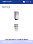
INSTALLATION GUIDE
®
MODULAR 3000 SERIES
120V, 3018CLR MODELS
U-3018CLROL-00
U-3018CLROL-01
U-3018CLROL-40
U-3018CLROL-41
U-3018CLRS-00
U-3018CLRS-01
U-3018CLRS-40
U-3018CLRS-41
THE MODULAR 3000 SERIES ARE INTENDED FOR BUILT-IN INSTALLATIONS ONLY
The American Built-In Undercounter Leader Since 1962
U-LINE.COM
Table of Contents
1 - Safety Precautions
Safety Alert Definitions.........................................................................................................................................1
General Precautions ..............................................................................................................................................1
2 - Inspect & Plan
Product Registration .............................................................................................................................................2
Product Description..............................................................................................................................................2
Tools/Materials Required .....................................................................................................................................2
Exterior Cleaning ...................................................................................................................................................2
3 - Prepare Site
Electrical Specifications .........................................................................................................................................3
Cut-Out Dimensions.............................................................................................................................................3
3018CLR Series ........................................................................................................................................... 3
4 - Product Dimensions
3018 Series ..............................................................................................................................................................4
5 - Door Swing Dimensions
Other Site Requirements .....................................................................................................................................5
Side-By-Side Installation............................................................................................................................. 5
Power Supply ............................................................................................................................................... 5
Environmental Requirements ................................................................................................................... 5
6 - 3000 Series Doors
Door Alignment and Adjustment.......................................................................................................................6
7 - 3000 Series Overlays
Overlay / Frame Overlay Panel...........................................................................................................................7
Panel Preparation ........................................................................................................................................ 7
Panel Installation.......................................................................................................................................... 7
Overlay Grille .........................................................................................................................................................9
Prepare and Install Overlay ...................................................................................................................... 9
Overlay Grille Dimensions ....................................................................................................................... 9
8 - 3000 Series Anti-Tip Bracket
Anti-Tip Bracket Installation..............................................................................................................................10
9 - Level & Install
Leveling Information ............................................................................................................................................11
Installation..............................................................................................................................................................11
Installation Troubleshooting.................................................................................................................. 11
10 - Prepare Plumbing
1/4" Copper Water Supply Connection.........................................................................................................12
U-Line Water Hookup Kit Connection..........................................................................................................13
11 - Drain Connection
Gravity Drain ........................................................................................................................................................14
Factory Installed Drain Pump............................................................................................................................14
Drain Connection ................................................................................................................................................15
Final Installation ....................................................................................................................................................15
General Precautions
1 Safety Precautions
Use this appliance for its intended purpose only and follow these
general precautions with those listed throughout this guide:
NOTICE
• PLEASE READ all instructions before installing,
operating, or servicing the appliance.
• Proper installation procedures must be followed when
completing an installation or relocation of a unit. An
INSTALLATION GUIDE for the unit, providing complete
installation information, is available from U-Line
Corporation direct. Consult the installation guide before
any installation begins. U-Line contact information
appears on the rear cover of this guide.
• This unit requires connection to a dedicated 15 Amp
grounded (three-prong), polarized receptacle, installed by
a qualified electrician, compliant with applicable electrical
codes.
Safety Alert Definitions
Throughout this guide are safety items labeled with a Danger,
Warning or Caution based on the risk type:
! DANGER
RISK OF CHILD ENTRAPMENT. Before you throw away your
old refrigerator or freezer, take off the doors and leave shelves
in place so children may not easily climb inside.
! WARNING
• SHOCK HAZARD - Electrical Grounding Required.
• Never attempt to repair or perform maintenance on
the unit until the electricity has been disconnected.
• Never remove the round grounding prong from the
plug and never use a two-prong grounding adapter.
• Altering, cutting of power cord, removal of power cord,
removal of power plug, or direct wiring can cause
serious injury, fire and/or loss of property and/or life,
and will void the warranty.
• Never use an extension cord to connect power to the
unit.
• Always keep your working area dry.
! DANGER
Danger means that failure to follow this safety statement will
result in severe personal injury or death.
! WARNING
Install provided Anti-Tip kit on all 3000 series units.
Serious personal injury could occur.
! WARNING
Warning means that failure to follow this safety
statement could result in serious personal injury or death.
! CAUTION
Caution means that failure to follow this safety statement
may result in minor or moderate personal injury, property
or equipment damage.
! CAUTION
• Use care when moving and handling the unit. Use gloves
to prevent personal injury from sharp edges.
• If your model requires defrosting, DO NOT use an ice pick
or other sharp instrument to help speed up defrosting.
These instruments can puncture the inner lining or
damage the cooling unit. DO NOT use any type of heater
to defrost. Using a heater to speed up defrosting can
cause personal injury and damage to the inner lining.
NOTICE
• Do not lift unit by door handle.
• Never install or operate the unit behind closed doors. Be
sure front grille is free of obstruction. Obstructing free
airflow can cause the unit to malfunction and will void the
warranty.
• Failure to clean the condenser every six months can cause
the unit to malfunction. This could void the warranty.
• Do not Block any internal Fans.
Use only genuine U-Line replacement parts. Imitation parts
can damage the unit, affect its operation or performance
and may void the warranty.
u-line.com
1
Tools/Materials Required
2 Inspect & Plan
• Screwdrivers — slotted, Phillips, and T-25 Torx head
• Level
Product Registration
You have received a carton containing your 3000 series unit with a
package inside containing a Quick Start Guide and a Registration
Card. Please complete and mail the Product Registration Card. You
may also register the unit online at u-line.com. Go to the Customer
Service tab and click on Product Registration. Once your unit is
installed, keep the Quick Start Guide in a safe place for future
reference.
Product Description
• Pliers
Exterior Cleaning
NOTICE
Stainless door panels, handles and frames can discolor when
exposed to chlorine gas, pool chemicals, salt water or
cleaners with bleach.
• Keep your Stainless unit looking new by cleaning with a good
quality all-in-one stainless steel cleaner/polish on a monthly basis.
For best results use Claire Stainless Steel Polish and Cleaner,
which can be purchased from U-Line Corporation (Part numbers
173348). Frequent cleaning will remove surface contamination
that could lead to rust. Some installations may require cleaning on
a weekly basis.
This installation guide covers the following models.
U-3018CLROL-00
U-3018CLROL-01
U-3018CLROL-40
U-3018CLROL-41
• Do not clean with steel wool or abrasive pads.
U-3018CLRS-00
• Do not use cleaners that are not specifically intended for
stainless steel on stainless surfaces (this includes glass,
tile and counter cleaners).
U-3018CLRS-01
U-3018CLRS-40
• If any surface discolors or rust appears, clean it quickly with BonAmi or Barkeepers Friend Cleanser and a non-abrasive cloth.
Always clean in the direction of the grain. Always finish this
process with Claire Stainless Steel Polish and Cleaner or
comparable product to prevent further problems.
U-3018CLRS-41
Inspection
Unwrap and inspect the unit on a flat, level surface capable of
supporting its entire weight. If necessary, remove protective film from
Stainless Steel models.
• Glass surfaces may be cleaned with standard household window
cleaners.
! CAUTION
Rust that is allowed to linger can penetrate into the surface
of the stainless steel and complete removal of the rust may
not be possible.
2
u-line.com
Cut-Out Dimensions
3 Prepare Site
3018CLR Series
Your U-Line product has been designed exclusively for a built-in
installation. When built-in, your unit does not require additional air
space for top, sides, or rear. However, the front grille must NOT be
obstructed.
Preferred location for
3018CLR drain, water
line and receptacle is
in adjacent cabinet.
The Modular 3000 Series units are engineered with a variety of
adjustment features to help ensure a seamless installation. adjustable
doors, leveling legs and grille will assist in fine tuning the installation.
All 3000 Series models fully integrate into overlay/face frame, inset or
European/frameless cabinet styles and install seamlessly into standard
24" depth cabinet base.
33-7/8"
to
34-7/8"
24"
5/8"
NOTICE
• Unit can NOT be installed behind a closed cabinet door.
• U-Line products are designed and manufactured to be
seamlessly installed in the specified cut-out openings
shown, and variance to the floors or cabinetry must be
accounted for in your installation.
17-3/4"
Electrical Specifications
! WARNING
SHOCK HAZARD — Electrical Grounding Required.
• Never remove the round grounding prong from the plug
and never use a two-prong grounding adapter.
• Never use an extension cord to connect power to the
unit.
NOTICE
Electrical installation must observe all state and local codes.
This unit requires connection to a grounded (three-prong),
polarized receptacle that has been placed by a qualified
electrician.
The unit requires a grounded and polarized 115 VAC, 60 Hz, 15A
power supply (normal household current). An individual, properly
grounded branch circuit or circuit breaker is recommended. GFCI
(ground fault circuit interrupter) is usually not required for fixed
location appliances and is not recommended for your unit because a
GFCI could be prone to nuisance tripping. However, be sure to
consult your local codes.
See Cut-Out Dimensions for recommended receptacle location.
u-line.com
3
4 Product Dimensions
3018 Series
23-1/4"
33-11/16"
to
34-11/16"
3-5/8" to 4-5/8"
17-3/4"
Solid Overlay Door
24"
33-11/16"
to
34-11/16"
3-5/8" to 4-5/8"
17-3/4"
Stainless Steel Solid Door
4
u-line.com
Other Site Requirements
5 Door Swing Dimensions
Side-By-Side Installation
Units have a zero clearance when the door to open 90°. Overlay
models will need additional space for any knobs or pulls installed on
the overlay panel / frame. Stainless Steel models require 2" door
clearance to accommodate the handle if installed next to a wall.
Wall
Cut-out width for a side-by-side installation is the total of the widths
listed under Cut-Out Dimensions in each unit’s Installation Guide.
No trim kit is required. However, a 1/4-inch (6.4 mm) of space needs
to be maintained between the units to ensure unobstructed door
swing.
Units must operate from separate, properly grounded electrical
receptacles placed according to each unit’s electrical specifications
requirements.
Power Supply
20-3/4"
(527 mm)
The unit requires a grounded and polarized 115 VAC, 60 Hz, 15A
circuit (normal household current). See Electrical Specifications.
Environmental Requirements
The units are designed to operate between 50°F (10°C) and 100°F
(37°C). High ambient temperatures (100°F [37°C] or higher) may
reduce the unit’s ability to reach low temperatures and/or may also
reduce the ice production rate for those models with icemakers.
20-1/8"
(511 mm)
90°
Door Swing
For best performance, keep the unit out of direct sunlight and away
from heat generating equipment.
In climates where high humidity and dew points are present,
condensation may appear on outside surfaces. This is considered
normal. The condensation will evaporate when the humidity drops.
Space Required
For any Knobs or Pulls
Overlay
2" MIN
(51 mm MIN)
Wall
20-3/4"
(527 mm)
90°
Door Swing
20-1/4"
(514 mm)
Stainless
u-line.com
5
3. Gently pull bottom of wrap away from door.
6 3000 Series Doors
4. The wrap hinges on top of the door. Carefully pull wrap away and
then up. See below.
Door Alignment and Adjustment
Align and adjust the door if it is not level, or is not sealing properly. If
the door is not sealed the unit may not cool properly, or excessive
frost or condensation may form in the interior.
Step 2
Door Top
NOTICE
Properly aligned, the door’s gasket should be firmly in
contact with the cabinet all the way around the door (no
gaps). Carefully examine the door’s gasket to assure that it is
firmly in contact with the cabinet. Also make sure the door
gasket is not pinched on the hinge side of the door.
! CAUTION
• Do not attempt to use the door to raise or pivot your unit.
This would put excessive stress on the hinge system.
• Pay special attention to the Cable Arm. Make sure not to
over extend or damage it during door alignment.
Step 1
Stainless Models (Removing Wrap)
Door Bottom
1. Open door completely.
2. Using a Phillips screwdriver, remove the two wrap screws from the
bottom of the stainless steel door wrap.
5. Remove cable from display by pressing
in the release tab on the cable
connector.
Press Tab Down
Alignment and Adjustment
Wrap Screws
1. Using a T-25 Torx Bit, loosen each
pair of Torx head screws on both the
upper and lower hinge plate.
2. Square and align door as necessary.
3. Tighten Torx head screws on hinge.
4. Re-connect display and re-install stainless steel wrap.
Cable Arm
T-25 Torx Screw
T-25 Torx Screw
6
u-line.com
7 3000 Series Overlays
Overlay Panel Dimensions
Overlay / Frame Overlay Panel
BACK SURFACE MUST HAVE AMPLE FLAT SURFACE
TO MOUNT OVERLAY PANEL FLAT AND WITHOUT
INTERFERENCE
NOTICE
Due to differences in surrounding cabinetry the panel may
not perfectly align with door. The procedure below is
designed to provide a finished overlay panel that seamlessly
integrates with surrounding cabinetry.
3/4"
(19 mm)
17-1/2"
(445 mm)
Panel Preparation
A full overlay door panel completely covers the door frame and
provides a built-in appearance.
NOTICE
• The door panel must not weigh more than 20 lbs (9.1 kg).
• It is important to ensure that all drilled holes are drilled to
the correct depth in order to avoid splits in the wood
when hardware is installed.
• Appliance will need up to 34-1/2" (876 mm) to the under
side of the counter to leave room for leveling adjustments.
30"
(762 mm)
1. Cut the panels to the dimensions listed in the diagram below.
2. Optional: Stain or Finish panel to desired stain or color. Be sure to
closely follow the instructions provided by the manufacturer.
NOTICE
If finishing frame overlay, both sides of overlay must be
finished in order to prevent warping.
Solid Overlay
3. Optional: Install handles and hardware.
Panel Installation
1. Fully open door,
2. Starting at corner, pull gasket
away from door.
3. Continue to pull gasket free
from gasket channel.
4. Upon removal, lay gasket down
on a flat surface.
u-line.com
7
NOTICE
Make certain the display cable remains securely seated in
the inner door channel, see below.
Inner Door
Channel
Display
Cable
6. Secure overlay to door
using clamps. A robust
tape may also be used.
U-Line recommends the
use of bar clamps to
securely clamp the
overlay to the door. If
using tape be certain the
tape will not damage
overlay finish upon
removal.
7. Using a 7/64" drill bit,
drill 6 pilot holes into
the wood panel
1/2" (13 mm) deep using
the holes in the door
frame as a guide.
5. The frame should be aligned with the outside edge (opposite the
hinge) and high enough to align with the highest point in the door.
Align Top Of Panel With Highest Point Of Door
Align Frame
Against
Door Edge
First
8. Locate 6 of the #6x
1-1/2" screws provided
with your unit.
9. Using a Phillips
screwdriver, place one
screw into each of the 6
pilot holes and screw
down. Do not
overtighten screws.
Bar
Clamp
Door
Wood
Panel / Frame
Bar
Clamp
10. Be sure the screws force
their way past the opening on the gasket channel and sit flush
against the bottom of the channel.
NOTICE
Due to differences in floor construction or surrounding
cabinetry, the frame may not sit flush with the top of the
door.
Frame
Door
Overlay Panel
Overlay Panel
11. Remove clamps from door.
NOTICE
If frame requires additional adjustment after removing
clamps, slightly loosen each screw and adjust frame as
necessary. Tighten screws upon completion.
12. Starting at the corners, re-install the gasket into the gasket channel
in the frame. Make sure the gasket is fully seated. This may take
some force.
8
u-line.com
Overlay Grille
1-1/2"
A
The 3000 series grille is fully adjustable and can be set to match your
surrounding cabinetry dimensions. In addition to its adjustability, an
overlay may also be installed to truly provide a seamless appearance.
Prepare and Install Overlay
1"
1. Use the dimensions provided in the diagram Overlay Grille
Dimensions to cut and shape your grille overlay. Recommended
overlay thickness is between 1/4" (6.4 mm) and 3/8" (9.5 mm).
Dimension A will vary from 3-1/2" (89 mm) to 4-1/2" (114 mm)
based on your toe kick height.
Apply Tape To Shaded Area
4. Remove backing paper from double sided tape.
1-1/2"
5. Carefully align grille over overlay and press into position.
u-line.com
3018 Models
17-3/4"
3. Apply double sided tape to the backside of the overlay grill. Use the
diagram below for reference. U-Line recommends 3M™ VHB™
tape, a high strength bonding tape.
14-3/4"
2. Finish your grille overlay to match your surrounding cabinetry.
Finish front, back and edges to prevent warping. Carefully follow
the manufacturer’s recommendations for finish application and cure
times.
Dimension A may vary from a minimum of 3-1/4" to a maximum 4-1/4" depending on toe kick height.
Measure toe kick height and cut overlay to same dimension.
Overlay Grille Dimensions
9
3018CLR Side Mount
8 3000 Series Anti-Tip Bracket
Left View Of Cabinet
Right View Of Cabinet
Anti-Tip Bracket Installation
! CAUTION
The anti-tip bracket must be installed to prevent the unit
from tipping when doors are fully opened, or excess weight
is placed on the front of the unit.
The anti-tip bracket has multiple mounting choices, depending on
your particular cabinet arrangement. Using the following instructions,
secure the anti-tip plate to the unit and then to your cabinets. Find
the anti-tip bracket kit included inside your unit.
3018CLR Top Mount
Side mount configurations work well if you have a granite countertop
or do not wish to mount the bracket to the underside of your
countertop.
1. Align the bracket to the hinge side of your unit as shown above.
2. Align the anti-tip plate with the holes provided on the unit. Using
the 2 supplied black #8 x 1/2" screws, install screws through the
plate into the unit using a #2 Phillips head screwdriver.
3. Completely slide the unit into its position in the opening. Be
certain unit height is properly adjusted. (See LEVEL & INSTALL.)
Top mount configurations work well with fully secured wood or
laminate countertops.
1. Align the bracket on top of your unit as shown above.
4. Open the door completely. Make certain the door clears the
surrounding cabinetry.
2. Align the anti-tip plate with the holes provided on the unit. Using
the 2 supplied black #8 x 1/2" screws, install screws through the
plate into the unit using a #2 Phillips head screwdriver.
5. Using the anti-tip bracket as a template, use a 3/32" drill bit to drill
pilot holes, 5/8" deep into cabinetry frame.
3. Completely slide the unit into its position in the opening. Be
certain unit height is properly adjusted. (See LEVEL & INSTALL.)
Attach to the cabinet using the 2 supplied screws after leveling.
4. Open the door completely. Make certain the door clears the
surrounding cabinetry.
5. Using the anti-tip bracket as a template, use a 3/32" drill bit to drill
pilot holes, 5/8" deep into bottom of countertop.
Attach to the cabinet using the 2 supplied screws after leveling.
10
u-line.com
9
Installation
9 Level & Install
1. Plug in the power cord.
Leveling Information
2. Gently push the unit into position. Be careful to not entangle the
electrical cord, water line and drain line.
It is recommended that the unit is level once installed.
1. Use a level to check the
levelness of the unit from
front to back and from side
to side. Level should be
placed along top edge and
side edge as shown.
3. Re-check the leveling, from front to back and side to side. Make
any necessary adjustments. The unit’s top surface should be
approximately 1/8" (3.2 mm) below the countertop.
4. Install the 6 cabinet mounting screws for the anti-tip bracket.
5. Remove the tape from the glass shelves and wipe out the inside of
the unit with a clean, water-dampened cloth.
1
Installation Troubleshooting
Q: Problem
The door remains open unless it is pushed closed.
2
2. If the unit is not level, remove grille and adjust feet as necessary.
Use included tool to adjust the height of the rear leveler feet. Turn
screw clockwise to raise the rear foot, counter-clockwise to lower.
3. Check the levelness after each adjustment and repeat the previous
steps until the unit is level.
A: Solution
The hinges should be self-closing when the door is open
approximately 8" (203 mm). If this is not the case, make sure nothing
is caught in the hinge closing mechanism. Also, re-check leveling from
front to back of the unit and readjust if necessary. Make sure that
pivot plate is installed correctly.
Q: Problem
The custom overlay door was designed to align with the rest of the
cabinet doors, but the unit has crept forward.
A: Solution
Rotate Forward Feet to Adjust
Make sure that the electrical cord, water supply line or drain line is
not obstructing the installation.
Rotate Clockwise to raise rear leg.
Rotate Counter-Clockwise to lower leg.
INSTALLATION TIP
If the room floor is higher than the floor in the cut-out opening,
adjust the rear feet to achieve a total unit rear height of 1/8" (3 mm)
less than the opening’s rear height. Shorten the unit height in the
front by adjusting the front feet. This allows the unit to be gently
tipped into the opening. Adjust the front feet to level the unit after it
is correctly positioned in the opening.
u-line.com
11
3. Remove front panel of unit. See image below for location of front
panel screws.
10 Prepare Plumbing
The unit requires a 1/4" O.D. soft copper supply line, or flexible
water supply kit from U-Line (Part No. WATERHOOKUP).
Remove screws
(one on each side)
to access behind
the front panel
! WARNING
Prior to attempting installation, determine if this product
contains a gravity style drain or factory installed drain
pump. Products without a drain pump may only use a
gravity style drain. Failure to connect water supply or
drain line connections properly may result in water
leakage, personal injury, and/or property damage.
Disconnect power and turn off water to the unit before
attempting to alter these connections. Please consult
U-Line or your installation instructions for further details.
These connections are the responsibility of the owner and
must be connected per local plumbing code. If you are
uncertain of how to safely and properly install this
product, contact a licensed plumber.
Water Connections:
! CAUTION
Review, obey, and understand the local plumbing codes
before you install your unit. Connect to the cold water
supply. The water pressure should be between 20 and
120 psi. The water line MUST have a shut-off valve on the
1/4" supply line.
! CAUTION
Front Panel
4. Locate the desired cold water supply location.
5. Attach a 1/4" copper line to this
location and route the tubing to the
appliance. Leave approximately 8' of
water line to be coiled behind the
appliance. The water line should be
looped into 2 coils. This will allow
the line to flex when removing the
unit for cleaning and service. Do not
kink or pinch the coiled line.
6. Take the end of the copper tubing
and put the line through the hole in the back panel.
7. Then take the end of the copper tubing and feed it through the
opening between the condenser and the side of the unit. The
copper tubing should be within two inches of the top of the
compartment.
• U-Line requires the use of copper tubing for installation or
the U-Line water hookup kit available at www.u-line.com.
This kit includes a flexible water supply connecting hose
and brass fitting.
• Do not use any plastic water supply line. The line is under
pressure at all times. Plastic may crack or rupture with
age and cause damage to your home.
• Do not use Teflon tape or joint compound on the water
fitting. The rubber washer provides an adequate seal.
Other materials could cause blockage of the valve.
• Failure to follow recommendations and instructions may
result in damage and/or harm, flooding or void the
product warranty.
1/4" Copper Water Supply Connection
! CAUTION
Turn off water supply and disconnect electrical supply to
unit prior to attempting installation.
1. Turn off water supply and disconnect electrical supply to product
prior to attempting installation.
2. Remove back panel of unit.
12
u-line.com
Water inlet line
should be within 2
inches of the top of
the compartment
8. Locate the U-Line supplied hose fitting. Ensure the end on the
copper tubing has been cut straight and is free of burrs. Slide the
compression nut and ferrule onto the copper tubing as shown
below.
4. Take one end of the braided line and feed it through the front of
the unit between the condenser and the right side of the unit. This
tubing should be within two inches of the top of the compartment.
Water inlet line
should be within 2
inches of the top of
the compartment
9/16" Wrench
1/4" Copper Water
Supply Line
Ferrule
Compression Nut
7/16" Wrench
From Water Supply
to Ice Maker
9. Feed the complete assembly into the garden fitting and tighten.
Attach to the water valve located in the front of the unit.
10. Gray hooks are located in the front of the condenser and behind
the condenser. Use these to secure the copper tubing to be within
two inches of the top of the unit.
11. Turn on water and check for leaks.
5. Take the end of the braided line and put the line through the hole
in the back panel.
6. Locate the desired cold water supply location.
7. Attach the end of the braided line to this cold water supply
location. Leave approximately 4' of water line to be coiled behind
the appliance.
8. Attach the garden hose connection from the kit to the front of the
unit.
12. Re-attach back panel and front panel.
U-Line Water Hookup Kit Connection
! CAUTION
Turn off water supply and disconnect electrical supply to
unit prior to attempting installation.
1. Turn off water supply and disconnect electrical supply to unit
prior to attempting installation.
9. Attach the front of the braided line to this garden hose connection.
Ensure that there is still approximately 4' of water line is coiled
behind the appliance. The water line should be looped in 2 coils.
This will allow the line to flex when removing the unit for cleaning
and servicing. Do not kink or pinch the coiled line.
10. Turn on water supply and check for leaks.
11. Re-attach back panel and front panel.
2. Remove back panel of unit.
3. Remove front panel of unit. See image below for location of front
panel screws.
Remove screws
(one on each side)
to access behind
the front panel
Front Panel
u-line.com
13
11 Drain Connection
! WARNING
The 3018CLR requires access to either a gravity or pump fed drain.
! CAUTION
If your U-Line unit did not come with a factory installed
drain pump you must use a gravity style drain connection.
For assistance in determining if your unit has a pump please
contact U-Line. The floor drain must be large enough to
accommodate drainage from all attached drains. Follow
these guidelines when installing drain lines to prevent water
from flowing back into the ice maker storage bin and/or
potentially flowing onto the floor, which may result in
personal injury or property damage.
Failure to connect water supply or drain line connections
properly can result in personal injury and property
damage. Gravity drain connections must be routed
downward from the rest of the unit at the rate of 1/4" per
foot.
Factory Installed Drain Pump
• If your drain line will run up to a stand pipe, disposal or spigot
assembly, or does not otherwise meet the requirements for a
gravity drain, you may have ordered the 3018CLR with a preinstalled U-Line P60 drain pump.
• If you need to install a P60 drain pump into your unit, see Locally
Installed Drain Pump on page 15.
• See below for typical installations requiring a drain pump.
NOTICE
Stand Pipe
P60 Pump Required
Drain can NOT be located directly below the unit. Unit has a
solid base that will not allow the unit to drain below itself.
NOTICE
Waste
There is a possibility that hose connections may have
loosened during shipment.
Shut-Off
Valve
Gravity Drain
Hot
Water
Normal
Proper Drain
Cold
Water
Waste
Disposal Assembly
P60 Pump Required
Air Gap
(Optional Hook-Up)
With Trap
Poor Drainage, Water Will Back Up
Waste
With Trap and Vent
Proper Drain
Hot
Water
A gravity drain may be used if:
Cold
Water
Shut-Off
Valve
• Drain line has at least a 1" (25.4 mm) drop per 48" (1219 mm) of
run (1/4" [6.4 mm] per foot).
• Drain line does not create traps and is vented per local code.
Y-Branch Tailpiece
P60 Pump Required
Air Gap
(Optional Hook-Up)
1. Cut the pre-installed drain tube to length.
2. Connect to your local plumbing per the local code.
3. If necessary, insulate drain line to prevent condensation.
Waste
4. Test the drain system per the test procedure under Final
Installation.
Shut-Off
Valve
Hot
Water
14
u-line.com
Cold
Water
Final Installation
NOTICE
The maximum lift for the P60 drain pump is 10 feet. This
must be done as close to the rear of the unit as possible.
NOTICE
Before installing your U-Line 3045CLR with factory-installed
U-Line P60 pump, it is extremely important to check and
test all hose connections at the drain pump.
NOTICE
NOTICE
In the event of a power outage, restricted drain or pump
failure, the failure to use the U-Line P60 drain pump could
result in substantial water leakage and pooling with severe
and costly water damage and related consequential
damages and harm.
1. Plug in unit and put into OFF mode by holding the power key for
5 seconds.
2. Turn on the water supply and ensure the connections are free of
leaks.
There is a possibility that hose connections may have
loosened during shipment.
Test Hose Connections:
3. Pour 1 gallon of water into the bin and ensure all the connections
and fittings are free from leaks.
1. Place a suitable container beneath the pump’s discharge tube. The
container must be able to hold a minimum of one gallon.
4. Begin to push the appliance into the desired cabinet opening. The
copper tubing should remain in 2 coils behind the unit.
2. Plug the ice maker power cord into a properly grounded, polarized
electrical outlet.
3. Place the unit into OFF mode by holding the power key for 5
seconds. Failure to power down the ice maker will cause it to begin
a fill cycle which will run for 3 minutes.
4. Verify pump operation by pouring one gallon of water into the ice
storage bin of the ice maker. The pump should energize and pump
the water into the container.
5. At this time, verify that all tube and clamp connections are tight
and leak-free.
6. Unplug unit power cord from electrical outlet.
NOTICE
Normal operation creates some vibration. A water supply
line contacting the cabinet may cause excessive noise during
operation, or damage the line. Make certain the water line is
not in contact with the cabinet and is routed using the preinstalled clips.
5. While pushing the unit into the opening, continuously reroute the
drain tube and water line to avoid kinks. The most common
installation pulls the slack into an adjacent cabinet or basement
area.
6. When installation is complete and unit is secured in the opening,
pour 1 gallon of water into the unit and ensure the water drains
from the bin and there is no water leakage in and around product.
Drain Connection
! WARNING
To prevent accidental electrocution and / or slipping,
make certain the floor surfaces surrounding the unit are
dry at all times.
1. Route pre-installed drain tube and cut to length. Connect to local
plumbing per code. Common fittings and clamps have been
included for your convenience. Avoid dips or sags in the drain line
and ensure the maximum lift is under 10' (3 m).
2. Insulate the drain line, if necessary to prevent condensation.
3. Test the drain system per the test procedure under Final
Installation.
! CAUTION
Failure to properly perform the installation of water supply
and drainage connections may result in water leakage, which
can damage the unit, damage other property and result in
personal injury through electrocution and/or slips and falls.
As a result, failure to properly install and connect the water
supply and drainage connections shall serve to void U-Line’s
warranty on the supplied equipment. In no event shall
U-Line be responsible for direct, indirect, incidental,
consequential or any other damage arising from improper
water supply and drain installation and/or connections.
Locally Installed Drain Pump:
If a gravity drain connection is not possible, and you have not
purchased a 3018CLR without a factory installed pump, we strongly
recommend the use of the U-Line P60 drain pump.
The U-Line P60 drain pump is available through your dealer, with
complete installation instructions.
u-line.com
15
INSTALLATION GUIDE
®
PRODUCT INFORMATION
Complete Installation Guides, Use and Care Guides, Specifications & Features and Benefits, CAD Drawings,
Overlay Panel/Frame and Toe-Kick Specifications and Instructions, Compliance Documentation and Applicable
Energy Guides are available for reference and download at u-line.com.
SERVICE INFORMATION
Please consult your Use and Care Guide for troubleshooting information. Answers to Customer Frequently Asked
Questions are available at u-line.com under Customer Service. You may contact U-Line directly:
GENERAL INQUIRIES:
SERVICE ASSISTANCE:
U-Line Corporation
P.O. Box 245040
Milwaukee, Wisconsin 53224-9540 U.S.A.
Phone 1-414-354-0300
FAX 1-414-354-7905
Email: [email protected]
u-line.com
Phone 1-800-779-2547
FAX 1-414-354-5696
Email: [email protected]
u-lineservice.com
PARTS ASSISTANCE:
E-mail: [email protected]
BUILDING ON THREE GENERATIONS OF INNOVATION
For over five decades and through three generations, U-Line continues to be the leader in innovation, quality and
performance in the premium built-in undercounter ice making, refrigeration and wine preservation market. U-Line
has captivated those with an appreciation for the finer things with exceptional functionality, style, inspired
innovation and attention to even the smallest details. We are known and respected for our unwavering dedication
to product design, quality and selection.
In 1962, Henry Uihlein founded U-Line Corporation as an outgrowth of Ben-Hur Freezer Company and was the first
to develop and patent an automatic stand-alone undercounter residential ice maker. His foresight and determination
to develop new ideas and to succeed when there were no clear guidelines or solutions are evident today. The newest
Uihlein generation continues to build upon the family’s innovative legacy at the Milwaukee, Wisconsin based business
by providing continuity and vision from which new designs and technology continue to be born.
Today the complete U-Line product collection includes Ice Makers, Ice Machines, Wine Captain® Models, Combo®
Models, Refrigerator / Freezers, Refrigerators, Drawer Models and Beverage Centers. The U-Line brand offers
products in the 1000 Series, 2000 Series and the Modular 3000 Series. The 1000 Series offers a more targeted
priced product with appropriate features, while the 2000 Series offers upscale features, advanced technology and
specialized product families. Our Modular 3000 Series provides sleek design and versatile temperature settings with
our U-Select® control. U-Line’s approach to its breadth of products, multiple price points and features allows a
choice and product that will fit any lifestyle.
DESIGNED, ENGINEERED AND ASSEMBLED IN WISCONSIN, USA
The American Built-In Undercounter Leader Since 1962
U-LINE.COM
©2013 U-Line Corporation
Publication Number 30385 5/2013 Rev.B