1
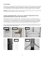
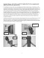
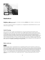
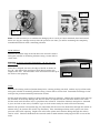
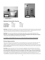
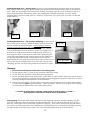
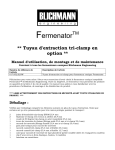
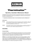
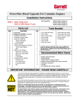
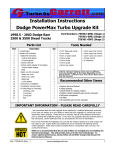
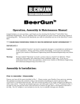
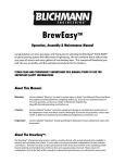
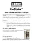
Fermenator tm NPT Models Operation, Assembly, Maintenance Manual F3-7, F3-14, F3-27 models and optional attachments Congratulations on your purchase, and thank you for selecting the FermenatorTM stainless conical fermentor from Blichmann Engineering. We are confident that it will provide you years of service and many gallons of outstanding beer and wine. This manual will familiarize you with the use, assembly, and the sanitation procedures for the product. **** PLEASE READ THOROUGHLY PRIOR TO USE FOR IMPORTANT SAFETY INFORMATION **** Unpacking: Please ensure that you have the following items packaged with your fermentor: 4 2 1 2 1 1 1 1 1 1 1 1 1 1 1 1 1 1 1 1 1 O-rings (27gal and 42gal model will have 2 smaller, 2 larger) Pressure relief valve o-rings (very small orange) Lid seal (large black seal installed on the lid) Ball valves O-ring retainer – (thin washer) Bottom dump fitting (1/2” NPT X 3/4” straight thread) 1/2” NPT 90 degree stainless steel street elbow 3/4-16 stainless steel hex nut (bottom dump) Racking arm fitting – ½” NPT X flare Racking tube (90 deg bent stainless tube) Racking tube nut Lid hatch (oval lid with handle) Pressure relief valve piston (stainless cylinder shaped part) Relief valve filter spring (installed on lid hatch) Large “T” nut (for V-band clamp) Airlock and stopper 1/2” NPT X 3/4” hose barb for bottom dump (nylon) 1/2” NPT X 3/8” hose barb (1/2” X 1/2” for 27gal model) for racking arm (nylon) 90 degree barbed elbow (3/8”) for connecting CO2 hose (nylon) 3/4” ID X 24” long hose for bottom dump Supplementary manual for installation of the F3-42 extension (if purchased) Note: some parts will be partially assembled to protect them during shipment. About This Manual: This manual is for the F3-7, 14.5, and 27gal NPT models and optional leg extensions and casters. If you purchased the optional 42gal modular extension for the 27gal model, or the complete 42gal model, you will have received a supplemental manual with the extension. This manual is broken down into the following sections: Assembly: Proper assembly procedures to ensure reliable, safe, leak-free operation of your FermenatorTM. Be sure to read the sanitizing section before the first use your FermenatorTM since most parts are sanitized before assembly. We recommend an initial assembly to familiarize you with the process prior to your first use. Sanitation: Steps to properly sanitize your fermentor before each use. Operation: Techniques to get the most out of your fermentor. Get years of service by properly maintaining and storing your fermentor. Storage & Maintenance IMPORTANT !! Warning: Sections labeled “Warning” can lead to serious injury or death if not followed. Please read these thoroughly and understand them completely before use. If you do not understand them or have any questions, contact your retailer or Blichmann Engineering (www.BlichmannEngineering.com) before use. Caution: Sections labeled “Caution” can lead to equipment damage or unsatisfactory performance of the equipment. Please read these sections thoroughly. If you have any questions, contact your retailer or Blichmann Engineering (www.BlichmannEngineering.com) before use. Assembly: Note: We recommend a trial assembly of your new FermenatorTM before using it to ferment so you are familiar with the procedures and are sure you have all the parts. When you are ready to use the fermentor for an actual brewing session, read the sanitizing procedures before assembling your FermenatorTM since many parts are sanitized before assembly. Note that some of the components have not been pre-assembled at the factory to prevent shipping damage. Threaded fittings All threaded fittings must be sealed with TeflonTM type pipe tape (recommended tape is in the back of this manual). Wrap each threaded fitting with 4-6 layers of good quality tape, particularly the lead thread. This will allow you to get a good seal without using excessive tightening force. Since you will not be sealing large pressures a “snug” fit is all that’s needed. Caution: Failure to use sealing tape, or over tightening, can cause thread galling (welding), which is not covered under warranty. If you feel any grinding while tightening stop immediately as this galling the threads! Threads, once galled, will not come apart! The key to long thread life is not over tightening, and using an adequate amount of thread sealing tape. 2 Bottom dump Assemble the elbow to the valve first, then the bottom dump fitting last as shown in Fig. 1. Be sure the handle of the valve faces up as in Fig. 2a and that the handle rotates outward. If you are using the optional leg extensions, it is not necessary to use the elbow, and will allow the trub and yeast to flow more freely. Simply install the valve directly on to the bottom dump fitting as shown in Fig 2b. If you are using the optional casters, assemble the bottom dump assembly as shown in Fig 2c so that the outlet does not interfere with the leg brace. You’ll be pressure testing all the fittings during the sanitation process, so if a leak is present you’ll be able to tighten it then. Install an o-ring (smaller o-ring for 27gal models) over the straight thread end of the bottom dump fitting, pressing it firmly against the bottom of the fitting. Place the o-ring retainer (stainless “washer”) over the o-ring (Fig. 1). Note that the o-ring and washer go on the OUTSIDE of the tank. Installing it on the inside of the tank will cause a steady leak to be present. Insert the fitting into the tank. Reaching in the tank, thread on the ¾”-16 stainless nut hand tight. Use a socket wrench with extension bar to tighten the nut until it bottoms-out, but be careful not to over tighten and damage the tank or threads. If you do not have a socket wrench, hold the nut still with your fingers and rotate the bottom dump assembly an additional ¼ to ½ turn (90 to 180 degrees) or until the fitting bottoms-out on the retaining ring. Fig. 2a Fig. 1 Fig. 2b Fig. 2c Caution: If you use use wrenches to tighten the o-ring fitting on the bottom dump do not over-tighten or you may damage the tank or the fitting. A snug fit is all that is needed to get a good seal. 3 Rotating racking arm Install the flare fitting on a valve, making sure the handle opens away from the tank. Install an o-ring in the o-ring groove on the flare end of the fitting. (Note: 27 gal models will use the larger o-rings on the racking arm. Insert the assembly into the hole in the conical side of the tank (see Fig. 4). Place the flare fitting nut on the racking tube and thread onto the flare fitting. Tighten the flare nut snugly with a wrench – do not over-tighten or you could inadvertently bend the tank while tightening. It is not necessary to excessively tighten the fitting to get a good seal. Install the tube in the same plane as the handle on the valve as in the photo (Fig. 3). This will allow you to use the handle as a guide to determine the position of the racking arm when draining the beer or wine. The racking arm should initially be positioned horizontally (below right). Fig. 3 Fig. 4 Tip: The only time it is necessary to rotate the racking arm is for the final racking of the finished beer. Limiting the rotation of the racking arm will reduce any possibility of a leak. Lid Assembly Place the U-shaped lid seal over the edge of the lid (not on the tank) with the small bead on the seal facing toward the lip of the tank as in Fig. 5. Place the lid on the tank and orient the hatch and airlock holes to your desired location. Be sure the lid is centered on the tank as much as possible. Place the V-band clamp around the lid and tank lip and start the T-nut on the clamp stud as in Fig. 6. The Vband clamp can be installed with either side up and with the clamp in any orientation. Note that the unit is shipped with a plain nut installed on the V-band to prevent shipping damage – it can be removed and discarded. Initially tighten the clamp to about 1/2” (13mm) of gap between the band segments (Fig. 7), then, using a rubber or wood mallet, gently tap the outside perimeter of the V-band clamp to seat the clamp firmly and evenly all the way around the lid seal. Start at the opposite side of the T-handle and work your way around to the handle. Retighten the clamp so the segment gap is less than 3/8” (13mm). Note: ALWAYS apply a dab of Vaseline or drop of oil on the threads of the draw bolt before each use to prevent wear and galling of the threads. Galled or warn threads are NOT covered under warranty. 4 3/8” (13mm) Max Gap Fig. 6 Bead Fig. 5 Fig. 7 Warning: Failure to correctly install and tighten the lid clamp can cause the lid to blow off during pressurization resulting in serious injury or death! Please contact your Authorized FermenatorTM Distributor or Blichmann Engineering (www.BlichmannEngineering.com) if you have any questions about proper assembly. Do not operate the unit until you are certain that you understand the proper installation procedure. Lid Hatch Install the pressure relief valve filter spring on the inside of the lid hatch as shown in Fig. 8. The purpose of this filter is to keep particles from clogging the relief valve, which may lead to a dangerous over-pressurization of the tank. Install lid in the oval hole in the lid (Fig 10). Place the small orange o-ring on the pressure relief valve piston (Fig. 9) and place it in the small hole in the lid as shown in the photo to the right (bottom). The weight of the piston will limit the pressure in the unit to 3 PSI. Warning: read the “Operation Section” prior to use to prevent Fig. 8 over pressurization of the fermentor !! It is critical that the pressure relief valve filter spring be installed on the lid to help prevent foreign material from clogging the pressure relief valve opening. Fig. 9 o-ring Fig. 10 5 Carry Handles The folding carry handles have been preinstalled on your fermentor. However, they have been tightened so they do not rotate in shipment and become damaged. Using two 7/16” wrenches, loosen the nylock nut so the handle moves freely. However, be sure the nut is still fully engaged on the bolt. The 7gal and 14.5gal models can be moved when full, but be sure to use 2 people to carry the 14.5 gal model. Warning: The 27gal model is too heavy to move when full. DO NOT attempt to move this unit when full. The carry handles are provided to move it only when empty. Optional Leg Extension Kits – F3-7, F3-14, and F3-27 models (For F3-42 see supplemental manual provided with that product) Assemble the legs and braces as shown in Fig. 11a, through 14 using the ¼-20 hardware provided. Note that the braces go on the inside of the leg. The washers also go on the inside of the leg as shown in Fig 13 and 14. It is recommended that you install all of the hardware finger tight first, and tighten the assembly when all fasteners are in place. This will allow slight adjustments of position as needed for ease of assembly. The leg extensions allow for gravity draining into a keg or bottling bucket. Note: it is not necessary to install the 90 degree street elbow on the bottom dump assembly when using the leg extension kit (ref Fig. 11a and Fig. 11b). This will allow the trub and yeast to flow more freely from the dump valve (see photo below left). Fig. 11a Fig. 11b Fig. 12 Fig. 13 Fig. 14 6 Optional Casters - F3-7, F3-14, and F3-27 models (For F3-42 see supplemental manual provided with that product) To assemble the casters, begin by pre-assembling the brackets as shown in Fig. 15 using two ¼-20 X ½” long bolts and washers. It is recommended that you install all of the hardware finger tight first, and tighten the assembly when all fasteners are in place. This will allow slight adjustments of position as needed for ease of assembly. Insert the large carriage bolts through the bracket and into the hole in the caster. Place a lock washer and nut on the bolt and finger tighten as shown in Fig 16. Invert your FermenatorTM and place on a soft surface to prevent scratching the lip. Place a caster assembly over each leg and hold in place with two ¼-20 X ¾” long bolts as shown in Fig. 17. Do not install nuts or washers at this time. Place the leg braces on the inside of the leg one at a time, installing washers and nuts on the bolts finger tight as shown in Fig. 18. Note that the braces go on the inside of the leg. Tighten all of the fasteners at this time, and invert the Fermenator onto the wheels. The wheels are non-marking to protect your floors, and feature a wheel lock to keep the unit in place and prevent accidental movement. Warning: Keep all wheels locked at all times unless moving the unit. Be sure all obstacles are out of the path of the Fermenator, especially small objects which will wedge under the wheels and cause it to suddenly stop moving. This will present a tipping hazard! While moving, keep both hands on the unit, and move slowly to prevent accidental tipping. When the unit is in its final location, lock all the wheels by depressing the wheel lock (Fig. 19) with your foot. Lock washer & nut Fig. 15 Fig. 16 Fig. 17 Fig. 18 7 Fig. 19 Sanitation: Caution: do NOT use any cleaner or sanitizer containing chlorine such as bleach. Over time, this will pit and erode stainless steel. Any other non-chlorine sanitizer is acceptable to use. IodophorTM or StarSanTM both work very well and do not require rinsing. Initial Cleaning: Prior to the first use, and after each subsequent use, scour the lid and tank with ordinary dish detergent (or any non chlorine based cleanser) such as PBW (Powdered Brewery Wash) and a ScotchbriteTM type green scouring pad. Do not use a steel wool scouring pad as the metal particles will rust on the surface of the parts. Rinse well and allow to dry thoroughly. Drying thoroughly allows the protective CrO2 layer to naturally re-form on the surface of the stainless steel. Scrub the fittings with a nylon brush and detergent, or soak in a solution of hot PBW. It is also acceptable to boil fittings and seals to sterilize them, however, remove the black vinyl grips from the valve handles and do not boil the grips. If you are not going to immediately use the fermentor, dry the fittings and seals thoroughly, and store them in a new plastic zip-lock bag (see storage section). Before each use: Fittings: Soak all fittings, valves, o-rings and lid seal in a sanitizing solution or boil in water for 10 min if you have not already done so after the last use (see storage section). Be sure to remove the black vinyl grips from the valve handles and do not boil the grips. To ensure that the inside pocket of the ball valve seal gets sanitized properly, fully close the valve, then open it until you see a small “cat’s-eye” opening as in Fig. 20. Or, if you wish, you can easily disassemble the valve completely for cleaning and sanitizing (Fig. 21). It is recommended that you completely disassemble the valves for a thorough cleaning after approx every 6 uses to prevent any contamination issues. Complete disassembly takes only a few minutes. 8 Fig. 21 Fig. 20 Note: it is not necessary to re-sanitize the fittings prior to use if you have sanitized, dried and stored them in a bag (see storage section) after the previous use since you will be sanitizing the completely assembled fermentor with a sanitizing solution. Lid & Lid Seal: Sanitize the outside edge of the lid where the seal will contact with grain alcohol or sanitizing solution using a cotton ball or clean cloth. Warning! alcohol is extremely flammable – do not use near open flame! Place the U-shaped seal over the edge of the lid as shown in Fig. 22. One side of the seal has a small bead running the length of the seal. The bead side of the seal must face the lip of the tank to seal properly. Bead Fig. 22 Tank: Sanitize the sealing surfaces (bottom dump hole, rotating racking arm hole, and the top lip of the tank) with grain alcohol or sanitizing solution using a cotton ball or clean cloth. Assemble the fittings on the tank per the previous assembly instruction section. Fill the tank with about a gallon of water and then add your sanitizer. Adding the sanitizer first will trap the sanitizer in the dump fittings and will not allow it to spread into the rest of the water in the tank. Fill the tank until the water level is just below the lid hatch. Install the lid hatch and place a sanitized 3-piece air lock on the unit (a “bubbler” type air lock cannot easily be used to fill the fermentor). Remove the pressure relief piston (Fig. 23) and slowly fill the rest of the fermentor through the airlock as shown in Fig. 24 (remove the airlock cap and float). Pour sanitizing solution until it pours out of the pressure relief valve opening. Replace the relief valve piston and continue filling through the airlock until it is full. This has flooded all the internal surfaces with sanitizer and purged all the air out of the tank. 9 Fig. 24 Fig. 23 Important: Dry the outside of the tank with a cloth and if any fittings are leaking, tighten them as required, taking care not to bend the tank. If you are unable to resolve a leak problem please re-read the fitting assembly instruction thoroughly taking special note of the location of the o-rings and retainers. If you are still experiencing a leak, contact Blichmann Engineering as this is not normal. After the prescribed time has passed for your sanitizer to finish it’s job, open both valves and drain the tank. If you have used a sanitizer that must be rinsed, open the tank and rinse as recommended. Alternate Sanitizing Method: An alternate method to sanitize the tank and lid is by using a surface sanitizer. This uses significantly less sanitizer. The only surface sanitizer we recommend is StarSan which has been specifically formulated as both a flood and surface sanitizer. However, the surface sanitizer concentration is stronger. Refer to the product instructions for dilution rates. Iodophor and other sanitizers are not recommended for this procedure. When all the fittings and components have been removed from the tank and lid, spray the inside surface of the tank and lid with sanitizer and let sit for 10 min. Repeat for another 10 min, then assemble as described above. Note that the fittings and other seals and components should still be immersed in sanitizer prior to assembly. The only drawback with this method is that you can’t check for leaks prior to filling. However, the sealing system has been extremely reliable and leaks are very uncommon. You are now ready to ferment!! Note: You can CIP (clean in place) the fermentor if you have the equipment. However, complete disassembly only takes a few minutes and is much more thorough and takes less overall time. Therefore, we recommend this method in lieu of the CIP method. It is also possible to surface sanitize the inside of the conical and lid (eliminates filling, and also leak check) using StarSan in a concentration for surface sanitation. However, you will need to soak the fittings, valves, seals in sanitizer as surface sanitizing is not effective with these parts. Operation: The FermenatorTM has been designed to fit in a large refrigerator, and about any chest or upright freezer. If you plan to use it in a freezer or refrigerator, the CO2 gas from fermentation should be vented through the door or wall of the refrigerator. For primary fermentation, it is highly recommended that you use a blow-off tube (not included). Fit the 90 degree barbed elbow (included) into the stopper as shown in Fig. 25 after primary fermentation. Run the hose to the exterior of the unit and affix it to an airlock as shown in Fig. 26. 10 Fig. 25 Fig. 26 *** IMPORTANT *** Maximum Fermentables Capacity 7 gal model: 14.5 gal model: 27 gal model: 42 gal model: Beer 5.5 US gal 11 US gal 21 US gal 33 US gal Wine 6.0 US gal 12 US gal 21 US gal 33 US gal Warning: Exceeding these capacities can cause the fermentation material (krausen) to clog the pressure relief valve and airlock causing a dangerous overpressure of the fermentor. Approximately 30% excess capacity is required for krausen space for beer and approximately 20% for wine. Warning: Do not use loose whole hops, wood chips, grape skins, or other similar material in the fermentor. Use a hop bag to prevent loose material from plugging the pressure relief valve or airlock, which may cause a dangerous overpressure of the fermentor. In addition, these materials will clog the racking tube making draining the finished beer/wine difficult. It is highly recommended that you use a blow-off tube for primary fermentation! Bottom dump operation Now you’re about to see the real benefit to a conical fermentor: the ease of trub (cold break) and yeast removal for secondary fermentation or yeast harvesting and quick and sanitary removal of wort samples. Typically, cold break is removed just after wort chilling, but prior to pitching the yeast (allow time for settling to the bottom of the tank). Remaining trub and flocculated yeast can be removed after primary fermentation. Procedure: Connect the clear 3/4” ID X 24” long hose (supplied) to the bottom dump valve with the hose barb fitting provided and place the other end into a suitable container. If you are not harvesting the yeast the hose and fitting do not need to be sanitized. If you have a large amount of sediment or it has compacted over time, it may take one to two minutes for the flow to begin. Over time, yeast takes on the consistency of toothpaste (as opposed to molasses) and even commercial breweries have trouble with plugging. More frequent dumping earlier in the fermentation process will alleviate this. It is recommended to dump when primary fermentation has slowed, and then every few days until the yeast 11 has all been removed. Performing a protein rest (for wheat and under modified malts) and using proper techniques to leave trub in the boil kettle will reduce the amount of trub carried into the fermentor and improve the quality of your beer. Consult any homebrewing text for recommended procedures. If you are still having trouble with yeast cake compaction it is permissible to use pressure to provide additional force to remove the yeast. This is a common procedure in commercial breweries. See the “Racking finished beer – pressure pumping” section for instructions and warnings before attempting this! Caution: Remove the pressure relief piston on the lid hatch prior to draining beer/wort from the tank or you will suck the liquid out of the airlock and into the fermentor! The CO2 from the actively fermenting beer is generally sufficient to purge any ingested air from the tank. Hold the valve body to prevent it from rotating, and slowly open the valve until you have removed the trub or yeast (the valves have a locking tab that needs to be lifted before opening). Watch the flow through the hose and close the valve when the trub and yeast have been drained. Reinstall the pressure relief piston. That’s it! Harvesting yeast: If you’re harvesting the yeast, you’ll need to sanitize the hose and fittings first. The valve threads can easily be sanitized by a spray bottle of sanitizer a few minutes prior to installing the barbed fitting. Allow the trub to pass first, and collect the cream colored yeast. A wide mouthed glass jar 8-16 oz works well. If you have CO2 available, purge the jar of oxygen before use. With proper sanitization techniques, yeast can be stored for 2-3 months and harvested up to 4 times in a typical homebrew environment. Since you’ll have plenty of yeast to pitch (reactivate in a starter if more than 2 weeks old) you’ll find your ferments starting faster and progressing much more quickly. Rotating Racking arm Operation This feature is used for taking wort samples during the fermentation process and for racking the finished beer into kegs or a bottling bucket. Caution: Remove the pressure relief piston on the lid hatch prior to draining beer/wort from the tank or you will suck the liquid out of the airlock and into the fermentor! The CO2 from the actively fermenting beer is generally sufficient to purge any ingested air from the tank. Wort sample: Hold the valve body to prevent it from rotating, and slowly open the valve until you have removed the sample. (the valves have a locking tab that needs to be lifted before opening). It is not necessary to rotate the racking arm to remove a wort sample. Limiting rotation of the racking arm will reduce the possibility of a leak. You do not need to connect a hose or barb to the valve to take a sample…just hold the sample tube up to the valve. Sanitize the valve with a spray bottle of sanitizing solution after use and dry with a paper towel or clean cloth, or just let it drip-dry. 12 Racking finished beer – gravity drain: Connect a clear sanitized hose and hose barb to the racking arm valve as shown in Fig. 27. The included nylon barbs seal well without Teflon tape so sanitation is easy. Hold the valve body to prevent it from rotating, and slowly open the valve, draining it into your keg or bottling bucket. Then slowly rotate the racking arm assembly downward as in Fig. 28-29, stopping when you see a yeast pick-up. That’s it! If you never see a yeast pick-up, leave it in the full down position. Fig. 29 Fig. 28 Fig. 27 Racking finished beer – CO2 pressure pumping: Connect drain hose as for gravity racking. Install 90 degree barbed elbow into airlock stopper as shown in Fig 30. Turn regulator pressure setting to zero PSI and close CO2 shutoff valve. Then connect hose to CO2 tank. Open racking arm valve, open CO2 shutoff valve and SLOWLY increase pressure on the CO2 regulator to a maximum of 3 PSI (6 ft of lift above racking arm) until beer or wine begins to flow. A slow flow rate will reduce disturbing the yeast cake and sediment and carrying into your keg. When you are getting toward the bottom of the tank be sure to lift the outlet end of the beer/wine hose above the surface of the beer or wine in the keg or bottling bucket to prevent the CO2 gas from “burping” the beer out of your keg when the fermentor is empty. Fig. 30 CO2 pressure Warning: Do not exceed 3 PSI (6 ft of lift above the racking arm) Do not tamper with, or press on the pressure relief valve piston Do not leave the fermentor unattended during pumping Do not use loose whole hops, wood chips, grape skins, or other similar material in the fermentor. Use a hop or grain bag to prevent loose material from plugging the pressure relief valve or airlock causing a dangerous overpressure of the fermentor. Ensure that the surfaces of the pressure relief valve piston and seat are free from fermentables or other material prior to pressurization. Clean as needed. Failure to do so may cause sticking and subsequent malfunction of the relief valve system. *** Failure to follow these warnings could result in serious injury or death *** This fermentor is NOT to be used for force carbonation! Dry-hopping: Do not use loose whole leaf hops for dry-hopping! Not only will they possibly clog the pressure relief valve, the leaves tend to clog the racking arm. If you use whole hops be sure to use a hop bag. Pellet hops can be used with or without a hop bag. In all cases, using a hop bag will reduce the carry-over of hop particles in the finished beer and harvested yeast. Boiling the bag before placing the hops inside is an easy way to reduce the risk of introducing bacteria in to the fermentor. 13 Wine Makers: The FermenatorTM is an outstanding vessel in which to ferment wine. The sealing system is far superior to wine tanks and is completely impervious to oxygen. Most stainless wine fermenting tanks have a loose fitting lid for primary fermentation (to vent gas) and a floating lid for secondary fermentation (to prevent oxygen infiltration). This floating lid has an inflatable seal with a “bicycle pump” and may leak over time. It is also a source for bacterial contamination from the fermentation material on the walls of the fermentor. Warning: Be 100% sure fermentation activity has completely ceased by verification with a hygrometer. The hygrometer measurement should not change over a period of two weeks prior to replacing the airlock with a solid stopper. Wine-maker Warning: Loose oak chips or grape skins in the fermentor may clog the racking arm, bottom dump and overpressure relief system. (Ref “Dry-hopping” above). In addition, oak “saw dust” tends to clog the bottom dump fitting. Primary fermentation of musts “on the skins” is not recommended with a conical for these reasons. However, post press storage & maturation is an excellent application for a conical. After Use Cleaning and Storage: After use, rinse with hot water and completely disassemble the fermentor and fittings. Remove any remaining Teflon tape, and soak the fittings and seals in hot PBW solution or boil as in the sanitizing procedure. Remember to remove the black vinyl grips from the valve handles. Scrub the fermentor and lid with a Scotch-brite green scouring pad and ordinary dish detergent (or your favorite non-chlorine cleanser such as PBW) and rinse and dry thoroughly. It is not necessary to remove the legs for normal cleaning. If you have to remove a leg for any reason, make careful note of the placement of the spacer and washers. Reassemble identically and do not over tighten the nut. Thoroughly dry all seals and o-rings and store them in a plastic bag and place inside the tank for the next use. Be sure to remove all the o-rings from the fittings to prevent from taking a “set”. Install the lid and V-band clamp (without seal) to prevent dust from settling inside the unit during storage. Note: it is not necessary to re-sanitize the fittings prior to the next use if you have stored them in a bag. Proceed directly to the assembly stage as you will be sanitizing them after assembly. 14 Maintenance: Inspect lid seal and o-rings before each use. If they have cuts, abrasion or have taken a permanent set replace them (see parts list below). Never scrub the seals or o-rings with an abrasive pad or cleanser. Warning: do NOT use any cleaner or sanitizer containing chlorine such as bleach. This will pit and erode stainless steel. If the ball valves ever begin to drip, remove the handle and tighten the packing nut under the handle. If this persists, replacement valve seal kits are available through your retailer. Contact your local Fermenator Distributor for replacement parts and lid seals. Replacement O-rings (a few dollars for 25 pc.) and a very high quality 3 mil Military Spec Teflon tape can be purchased through: McMaster-Carr (www.McMaster.com) or (404) 346-7000 Small O-ring cat. # Larger O-ring cat. # Relief valve piston O-ring cat # Teflon tape cat. # 9561K27 (for racking arm on 7/14.5gal models and bottom dump on all models) 9561K31 (for racking arm on 27gal model) 9396K13 6802K33 Warranty: Blichmann Engineering products are warranted to be free of defects in materials and workmanship for a period of 1yr from the date of purchase (proof of purchase required). Specifically excluded from this warranty are o-rings, normal wear and tear, damage from abuse, misuse, failure to follow cleaning and maintenance procedures, and thread galling or breakage from over tightening or failure to use Teflon thread tape where instructed. Blichmann Engineering is not responsible for incidental or consequential damage arising from use or misuse of this product. This product is intended for home use only. No warranty or guarantee of suitability (express or implied) is given for commercial use of this product. Blichmann Engineering must be notified within 7 days of the delivery date of any hidden shipping damage. Owner is responsible for shipping damage outside of this time period. Customer is responsible to keep all original packing material for warranty returns – Blichmann Engineering, LLC is not responsible for damage from improperly packaged warrantee returns and these repair costs will be the responsibility of the customer. Resolution of warranty claims will be by repair or replacement and will be the decision solely of Blichmann Engineering. Shipping costs for warrantee returns are covered only for the contiguous United States. User is responsible for packaging costs and shipping damage if not returned in original packing. Approval for return (RMA) must be provided by Blichmann Engineering prior to any return. 15 F3 NPT Owners Manual – V9 Blichmann Engineering, LLC 2011 16