1
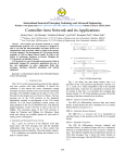
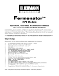
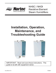
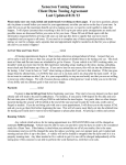
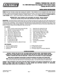
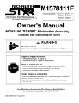
®
VICTOR X OPEN TRACK TURBOCHARGING SYSTEM
For 1994-1995 Acura Integra DOHC Vtec B18C1 - Catalog #1508
and 1996-2001 Acura Integra DOHC Vtec B18C1 - Catalog #1511
INSTALLATION INSTRUCTIONS
PLEASE study these instructions carefully before beginning this installation. Most installations can be accomplished with common tools and
procedures. However, you should be familiar with and comfortable working on your vehicle. If you do not feel comfortable performing this
installation, it is recommended to have the installation completed by a qualified mechanic. If you have any questions, please call our Technical
Hotline at: 1-800-416-8628, 7:00 am - 5:00 pm, Pacific Standard Time, Monday through Friday or e-mail us at [email protected].
IMPORTANT NOTE: Proper installation is the responsibility of the installer. Improper installation
will void your warranty and may result in poor performance and engine or vehicle damage.
PLEASE complete and mail your warranty card. Be sure to write the model number of this product in the "Part #____" space. THANK YOU.
DESCRIPTION: The Edelbrock Victor X Turbocharging System is intended for high boost pressure, off-highway applications in conjunction with
user provided and tuned engine management. The Garrett GT-28RS ball-bearing turbocharger can provide boost pressures up to 28 PSIG
(Pressure reading at boost gauge) on a modified B18C1 engine. The kit includes all of the components necessary for the mechanical installation
of the turbocharger system. The turbocharger is pre-assembled as one unit with a Ni-resist cast exhaust manifold and exhaust elbow, and inlet
oil and coolant lines for a simple installation. The system also includes an air-to-air intercooler, Tial blow-off valve, a Victor X intake manifold, and
all of the required fasteners, fittings, hoses, gaskets, and piping. NO ENGINE MANAGEMENT IS PROVIDED. An engine fitted with this kit using the
stock, un-modified engine management will not function properly, and damage to the engine WILL OCCUR.
BEFORE BEGINNING: Someone who has a basic knowledge of automobile repair and modification and is familiar with and comfortable with
working on their vehicle can accomplish the mechanical installation of this kit using common tools and procedures. However, successful operation
of the engine with this turbocharger kit requires a working knowledge of the set-up and tuning of an engine management system. The required
modifications to your engine and fuel delivery system are dependent on the boost pressure and power output you desire to run. For boost levels
above 8 PSIG, aftermarket pistons, connecting rods, and valves are required to assure engine durability. High boost pressures and power output
will also require an aftermarket high-volume fuel pump such as Edelbrock #17938 (190 liter/hr), #17936 (255 liter/hr), or #17937 (255 liter/hr,
60+ PSI for high boost levels). Customer tunable engine management packages are available from multiple manufacturers such as: AEM,
Hondata, Motec, F.A.S.T., Accel DFI, Apex, etc., and will be available from Edelbrock MotoTron in the near future.
NOTE: Exposed fuel and oil will be present during this installation:
WARNING: WHEN WORKING AROUND GASOLINE OR OIL, WORK IN A WELL VENTILATED AREA,
AND KEEP ALL OPEN FLAMES, SPARKS AND OTHER SOURCES OF IGNITION AWAY FROM THE WORK AREA.
FAILURE TO DO SO CAN RESULT IN A FIRE OR EXPLOSION.
NOTE: Some procedures in the installation will require the vehicle being raised on jackstands or a lift.
WARNING: WHEN RAISING A VEHICLE, MAKE SURE THE VEHICLE IS ON LEVEL GROUND AND SUPPORTED
SECURELY BY JACKSTANDS. NEVER WORK UNDER A VEHICLE THAT IS SUPPORTED BY A JACK ONLY!
AFTER INSTALLATION, BEFORE STARTING THE VEHICLE: We recommend the use of a synthetic 10W30 motor oil. Mobil1 was used in our
testing. Before starting the vehicle, the oil drain hose should be disconnected from the oil pan and the engine should be turned over with the
starter until oil is running out of the oil drain hose (Note: This may take one or two minutes of intermittent cranking for the oil system to be primed
and for oil to reach the drain hose. To keep from damaging the starter, crank the engine in 20-30 second intervals, until oil reaches the drain
hose). This will ensure that the turbo is lubricated before the initial start-up. This should be done with the spark plugs removed and the fuel
management/ignition system DISABLED to prevent accidental spark. Along with synthetic oil, we strongly recommend using a colder spark plug
in the engine.
Catalog #1508, #1511
Rev. 1/06 - RS/mc
Page 1 of 10
©2006 Edelbrock Corporation
Brochure #63-0488
KIT CONTENTS
Qty.
Description
Individual Parts
❑1
❑1
❑1
❑1
❑1
❑1
❑1
❑1
❑1
❑1
❑1
❑1
❑1
❑1
Turbocharger / Exhaust Manifold / Exhaust Elbow / Oil-Water Line Assembly
Victor X Intake Manifold
Oil Supply Sandwich Adapter Assembly (Note: A ½” allen wrench is required for installation of the adapter)
Intercooler
Compressor Inlet Pipe, Cast Aluminum
Compressor Outlet Pipe, Cast Aluminum
Intercooler Inlet Pipe
Intercooler Outlet Pipe
Intake Manifold Inlet Pipe
Coolant Pipe (Lower Radiator Re-Routing)
Exhaust Down Pipe
Air Filter / Attachment Hose / Clamps Assembly
Blow Off Valve Assembly
Gasket, Intake Manifold
Hardware Kit
❑3
❑1
❑1
❑7
❑6
❑ 13
❑3
❑3
❑4
❑2
❑2
❑2
❑1
❑1
❑3
Fuel Rail Spacers
Nylon Plug (Compressor Inlet Pipe Temp Sensor Hole)
3/8-18 NPT Pipe Plug (Intake Manifold Inlet Pipe Temp Sensor Hole)
M8 x 1.25 Stainless Steel Stud (Exhaust Manifold To Cylinder Head)
M8 x 1.25 Stainless Steel Nut (Exhaust Manifold To Cylinder Head)
M8 Stainless Steel Split Washer
M10 x 1.5 Studs (Exhaust Downpipe to Turbo Outlet Elbow)
M10 x 1.5 Flange Nut (Exhaust Downpipe to Turbo Outlet Elbow)
M8 x 1.25, 25mm Long Bolt (Compressor Outlet Pipe to Intercooler Inlet Pipe)
¼-20 x ½” Hex Head Bolt (Turbo Oil Drain Adapter Fitting, Steel Oil Pan)
Socket Head Cap Screw, M8 x 1.25, 20mm Long (Turbo Oil Drain Hose to Turbo Oil Drain Flange)
M8 Spring Washer (Turbo Oil Drain Hose Mounting)
M8 x 1.25, 12-point Stainless Steel Nut (Exhaust Manifold to Cylinder Head)
M8 x 1.25, 12mm Long, Serrated Flange Hex Head Bolt (Compressor Inlet to Support Brace)
M6, 30mm Long Serrated Flange Hex Head Bolt, Black Oxide Finish (Fuel Rail)
Hose Kit
❑1
❑1
❑1
❑1
❑1
❑1
❑2
❑2
❑ 3ft.
❑ 7ft.
Clutch Line
Turbo Oil Drain Hose Assembly
2” Silicone Hose Coupling (Compressor to Compressor Outlet Pipe)
2 ½” - 3” Silicone Hose Coupling (Compressor Inlet Pipe to Compressor)
2 ½ - 2 5/8” Silicone Hose Coupling (Intake Manifold Inlet Pipe to Throttle Body)
2 ¼” Silicone Hose Coupling (Intercooler Outlet Pipe to Intake Manifold Inlet Pipe)
2 ¼” - 2 ½” Silicone Hose Couplings (Intercooler Inlet/Outlet Pipes to Intercooler)
1 ¼ - 1 3/8” Silicone Hose Coupling (Coolant Re-Route Pipe)
3/8” Cam Cover Breather Hose
¼” Red Silicone Hose, Wastegate & Blow-Off Valve
Catalog #1508, #1511
Rev. 1/06 - RS/mc
Page 2 of 10
©2006 Edelbrock Corporation
Brochure #63-0488
KIT CONTENTS (Continued)
Hose Clamp Kit
❑1
❑4
❑5
❑2
❑4
❑2
Hose Clamp, 2 9/16” - 3 ½”
Hose Clamps, 2 1/16” - 3”
Hose Clamps, 1 13/16” - 2 ¾”
Hose Clamps, 1 9/16” - 2 ½”
Hose Clamps, 1 5/16” - 2 ¼”
Hose Clamps, 5/16” I.D.
Gasket Kit
❑1
❑1
❑1
❑1
❑1
❑2
❑4
❑1
❑1
❑1
❑2
Throttle Body to Intake Manifold Gasket
Turbo Outlet Elbow to Exhaust Down Pipe Gasket
MAT Sensor Gasket
O2 Sensor Bung Gasket (Second O2 Sensor Bung)
Oil Drain Adapter Fitting Gasket
¼” Stato Seal Washer (Turbo Oil Drain Adapter)
12.3mm I.D. / 16.2mm O.D. / 1.5mm Thick, Aluminum Crush Washer (Fuel Banjo Fittings)
Compressor Outlet Pipe to Intercooler Inlet Pipe O-Ring
Turbocharger Oil Drain Flange O-Ring
Inlet Air Temperature Sensor Grommet
Lower Intercooler Mount Grommets
Fitting Kit
❑1
❑1
❑1
❑1
❑2
❑1
❑2
❑2
❑2
❑1
❑2
❑1
❑1
Throttle Cable Bracket
Turbo Oil Drain Adapter Fitting
10mm Barb to ¼”NPT Adapter Fitting
17mm Barb to 3/8”NPT Adapter Fitting
3/16” Barb to 1/8”NPT Adapter Fitting
¼”NPT to ¼”NPT Female Street Elbow
1/8”NPT Pipe Plugs
¼” Barb to 1/8”NPT Adapter Fitting
8mm Barb to 1/8”NPT Adapter Fitting
9mm Barb to ¼”NPT Adapter Fitting
8mm Barb to ¼”NPT Adapter Fitting
3/8” Barb to ¼”NPT Male Adapter Fitting
Plug, O2 Sensor Bung (Second O2 Sensor Bung)
Catalog #1508, #1511
Rev. 1/06 - RS/mc
Page 3 of 10
©2006 Edelbrock Corporation
Brochure #63-0488
INSTALLATION INSTRUCTIONS
INITIAL PARTS REMOVAL (See factory service manual for procedures where noted)
1. Begin by disconnecting the battery and draining the engine oil and coolant from the engine.
2.
Remove the front lower splash shield and front bumper cover, as per the factory service manual procedure. The front inner fender liners do
not need to be removed. You can allow the front inner fender liners to hang free, remaining attached to the rear of the front wheel well
openings. Remove the stock intake tube and upper/lower air box following the service manual instructions. Save the air box mounting bolts
and grommets. These will be used to mount the compressor piping to the chassis.
3.
Remove the lower radiator hose. Disconnect the upper radiator hose from the radiator only. Allow the upper radiator hose to remain attached
to the cylinder head coolant outlet. (NOTE: Remember to catch any draining coolant in a pan. If it is clean, it may be re-used after the
installation is complete. Otherwise, dispose of it properly and replace with fresh fluid after finishing the installation.)
4.
Remove the bolt holding the horn onto the center radiator support and move the horn to the side.
5.
Remove the driver’s side tie down bracket (tow hook) located behind the lower radiator support.
6.
Under the vehicle, remove the Oxygen Sensor from the factory lower exhaust header (B-Pipe), and move to the side. Disconnect the factory
B-Pipe from the Catalytic Converter, inspect the donut gasket for wear. If it is in good shape, it may be re-used. Disconnect the B-Pipe from
the upper exhaust header. Remove the bolts holding the metal pipe portion of the heater hose to the intake manifold support bracket. Remove
the lower bolts of the bracket. From above the vehicle, remove the exhaust manifold heat shield and upper exhaust manifold. If exhaust
manifold gasket is not damaged, set it aside to be re-used.
7.
Remove the radiator cooling fan (passenger side). (NOTE: The turbocharger/exhaust manifold assembly will not clear the factory fan. You
must permanently remove the passenger side fan, or install a low-profile, aftermarket fan in place of the passenger side fan.)
8.
If your vehicle is equipped with air conditioning, remove the upper and lower A/C line support brackets and remove the radiator upper retaining
brackets. Set these aside.
CLUTCH LINE INSTALLATION
1. Remove the A/C line support bracket (if equipped) on the passenger side inner fender (See Fig. 1A).
2.
Remove the clip from the clutch line at the passenger side fender and disconnect the flexible clutch line. Use a rag or a drip pan to catch
any dripping clutch fluid. (NOTE: Be careful not to drip fluid on painted surfaces. Clutch/Brake fluid will damage paint.)
3.
Disconnect the clutch hard line on the transmission from the clutch slave cylinder. Remove the bolts holding the clutch line bracket on the
transmission bellhousing, and remove the bracket and clutch lines as an assembly (See Fig. 1B). Re-install bracket bolts into the bellhousing
and torque to factory specifications.
4.
Install the supplied Russell braided clutch line. Remember to re-install the factory clutch line retaining clips at each end of the clutch line.
5.
Bleed the clutch to remove any air in the clutch system. Refer to your factory service manual for proper procedure.
Remove bolts and
remove bracket
Remove Bracket
Assembly From
Bellhousing
Fig. 1A
Catalog #1508, #1511
Rev. 1/06 - RS/mc
Fig. 1B
Page 4 of 10
©2006 Edelbrock Corporation
Brochure #63-0488
Use 1/4-20 x
1/2” bolts &
Stato-Seal
washers
Oil pan rail
1.125”
Fig. 2A
Locate between 3rd
& 4th bolt hole from
driver side
Fig. 2B
1.50”
Keep clear of baffle
Fig. 2D
Fig. 2C
OIL DRAIN ADAPTER INSTALLATION (NOTE: Removal of the oil pan is required to install the turbo oil drain adapter)
1. Remove the front and rear stiffening brackets connecting the block to the bell housing (See Fig. 2A). Remove the bellhousing cover. Using
a 10mm socket, remove the oil pan nuts and bolts and remove the oil pan. If necessary, gently tap on the oil pan with a rubber or plastic
mallet to loosen the seal between the oil pan and the engine block. Carefully remove and inspect the oil pan gasket. If it is not cracked or
torn, it may be re-used.
2.
3.
The Oil Drain Adapter requires the oil pan to be drilled. Mark the area to
be drilled. Center the drain hole below the third bolt hole from the
driver’s side on the front of the oil pan (See Fig. 2B), 1.5” from the Oil
Pan Rail (See Fig. 2C). Using a scratch awl, mark the center of each
bolt hole 9/16” away from the center of the center drain hole so the
distance between the bolt holes, from center to center, is 1.125” (Fig.
2C). Make sure this location will not interfere with the oil baffle inside
the pan. If needed, move the location slightly to avoid any interference
with the baffle (Fig. 2D).
1
5
3
Apply Liquid Gasket
6
Using a center punch, indent each drilling location to prevent the drill bit
from walking. Pre-drill each hole with a 1/8” bit. Secure the oil pan on
a work bench or on a drill press, and drill the outer bolt holes to ¼”. Drill
the center drain hole to ½”. Deburr the holes and thoroughly clean the
oil pan to remove metal shavings.
Oil Pump
4
2
Fig. 2E
4.
Install the Oil Drain Adapter onto the oil pan using the two ¼-20 x ½” bolts (We recommend using blue Loctite on the threads) and the two
¼” Stato-Seal washers on the inside of the oil pan, using the gasket on the outside of the pan (See Fig. 2D). Torque the bolts to 6-8 ft/lbs.
5.
Apply sealant (Permatex Ultra Grey or equivalent) to the oil pump to block, and passenger side cover to block mating surfaces (See Fig. 2E).
Re-install the oil pan. Finger tighten nuts 1-6 to hold the pan in place (See Fig. 2E). Install remaining bolts finger tight. Tighten all nuts/bolts
to 8-9 ft/lbs. Start with nuts 1-6, and tighten the remaining bolts in a clockwise manner, starting in the center and working your way out.
6.
Re-install the bellhousing cover and front and rear stiffening brackets. Torque the bolts to factory service manual specifications.
TURBOCHARGER / EXHAUST MANIFOLD ASSEMBLY INSTALLATION
1. Using a zip-tie or twine, carefully flex the upper and lower A/C lines and the radiator as far forward as possible and temporarily secure. Also
flex the upper radiator hose towards the engine and temporarily secure with zip-ties or twine. This will provide additional clearance to place
the turbocharger/exhaust manifold assembly into position.
2.
Install the seven supplied 8mm x 1.25 studs into the exhaust manifold bolt holes. Hand tighten only. (NOTE: Do not re-use the factory
exhaust bolts. Some vehicles may have factory installed studs. These may be re-used, or replaced with Edelbrock studs, if desired.)
3.
Being careful not to damage the oil feed and coolant lines, or the radiator fins, bring the
turbo assembly into position by lowering it into the engine compartment. It is helpful to
lower it into the gap created by tying the upper radiator hose back, and moving the
assembly towards the driver side and into position on the exhaust manifold studs. Use
the stock exhaust gasket. (NOTE: If the gasket is in good condition, it may be re-used.
The gasket should show no signs of leaking, cracks, missing pieces, or burnt areas. If
the gasket is not in good condition, it should be replaced. Thoroughly clean flange of any
old gasket material.) Using the supplied 8mm x 1.25 12-point nut on the center exhaust
manifold stud (See Fig. 3), and the six supplied 8mm x 1.25 6-point nuts, attach the
turbo assembly to the engine block. You may need to bend the dipstick tube slightly to
clear the exhaust manifold (See Fig. 3). Refer to the Honda Factory Service Manual for
torque values and sequence.
Catalog #1508, #1511
Rev. 1/06 - RS/mc
Page 5 of 10
12-Point Nut
Dipstick Tube
Fig. 3
©2006 Edelbrock Corporation
Brochure #63-0488
4.
In some instances, the A/C line (if equipped) near the wastegate actuator may be
touching or rubbing on the wastegate actuator. If this is the case, carefully use a
pry bar and apply smooth, even pressure to slowly flex the line away from the
wastegate actuator until there is approximately 1/4” clearance between the A/C
line and the actuator (See Fig. 4).
5.
Lay out the Coolant Lines and Oil Feed Line in their approximate routing locations.
The Oil Feed Line (the line with the 6AN female fitting) should head down and
towards the driver’s side, then up along the driver’s side inner fender and towards
the back of the engine, taking care not to route the line in the way of any moving
parts (such as: pulleys, timing belts, etc.). The coolant lines should be routed
down toward the passenger side, then up and toward the rear of the engine.
A/C Line
Wastegate
Actuator
Fig. 4
FACTORY INTAKE MANIFOLD REMOVAL
1. Relieve fuel pressure first by loosening the banjo bolt connecting the fuel line to the fuel filter. Place a shop towel or rag over the wrench
while loosening the banjo to soak up any fuel spray (See Fig. 5). When loosening or tightening the banjo bolt on the fuel filter can, use a
19mm wrench of the hex of the fuel filter can to counteract the torque of loosening or tightening the banjo bolt. This will prevent the fuel
filter can and bracket from being improperly loaded during loosening or tightening at the banjo bolt.
2.
3.
Disconnect the fuel injector wiring harness from the bracket on the fuel rail and unplug the harness
from the fuel injectors (Mark the locations of each plug on the harness to prevent improper connection
during reinstallation). Disconnect the Throttle Position Sensor plug, MAP Sensor plug, EVAP Purge
plug, and Idle Air Control Motor plug. Disconnect the purge line from the purge valve. Disconnect the
fuel return line from the steel chassis fuel line. Disconnect the fuel feed line from the fuel filter.
Disconnect the coolant lines from the throttle body and manifold flange. Disconnect the vacuum lines
at the rear of the manifold. The intake manifold support bracket does not need to be removed from
the intake manifold. It can be removed with the intake as an assembly since the bolts attaching it to
the block were removed previously. Remove the throttle cable. Remove the factory intake manifold
nuts. Remove the intake manifold assembly and set aside.
Fig. 5
Stuff the open intake ports in the cylinder head with paper towels to prevent any debris from entering the engine. Thoroughly clean the gasket
surface removing any remaining sealant or gasket material.
OIL SUPPLY ADAPTER INSTALLATION
1. With the intake manifold removed, there will be much more clearance to install the
Oil Supply Adapter. Remove the stock oil filter (Replace). Install the Oil Supply
Sandwich Adapter in place of the stock oil filter. Make sure the O-Ring is facing
toward the engine block, and the threaded stud with ½” hex opening is facing out.
Tighten with a ½” Allen Wrench. Make sure the blue fitting is facing toward the
driver’s side, pointing upward slightly, about the 10 o’clock position. On 1511
installations, route the supply line such that it will pass between the knock sensor
and the coolant line (See Fig. 6). Install a new oil filter. Route the oil supply line
to the sandwich adapter. Using a light coat of oil on the threads, tighten the female
fitting onto the blue fitting on the sandwich adapter.
Fig. 6
VICTOR X INTAKE MANIFOLD INSTALLATION
1. (NOTE: Use teflon paste on the threads of fittings or plugs before installing them into the intake manifold.) Install the vacuum fittings and
the stock Manifold Air Temperature (MAT) sensor (or supplied block off plate) on the underside of the Victor X intake manifold (See Fig. 7A).
The kit includes numerous vacuum fittings and plugs which may or may not be necessary for your application. We suggest installing at least
the following fittings in a typical installation (use supplied plugs as necessary to block unused holes):
❑
❑
❑
2.
3/16” Barb x 1/8” NPT (For Fuel Pressure Regulator)
❑ 8mm Barb x 1/4” NPT (For PCV)
1/4” Barb x 1/8” NPT (For Blow Off Valve)
❑ 9mm Barb x 1/4” NPT (For Purge Valve)
1/4” NPT Street Elbow & 10mm Barb x 1/4” NPT (For Power Brakes)
Install the water outlet fitting into the mounting flange, and install the 1/8” NPT x 8mm barb fitting (or 1/8” NPT Pipe Plug for 1511
installations) into the water outlet fitting (See Fig. 7B). (Refer to Fig. 7C for thread sizes and Fitting Descriptions).
Catalog #1508, #1511
Rev. 1/06 - RS/mc
Page 6 of 10
©2006 Edelbrock Corporation
Brochure #63-0488
#10
#1 #2 #3 #4 #5
#6
#11
#7 #8 #9
Fig. 7A
#1
#2
#3
#4
#5
#6
#7
#8
#9
#10
#11
1/8” NPT
1/8” NPT
1/4” NPT
1/8” NPT
1/8” NPT
MAT Sensor (Or supplied block off plate)
1/8” NPT
1/4” NPT
1/4” NPT
17mm Barb x 3/8” NPT (Water Outlet)
8mm Barb x 1/8” NPT (Throttle Body
Coolant Hose. Use 1/8” NPT Plug on 1510)
Fig. 7C
Fig. 7B
3.
Remove the idle air control motor (IAC) from the factory intake manifold and install onto the Victor X intake manifold. Remove the throttle
body (with MAP sensor attached), and two throttle body studs from the factory intake manifold. Using two nuts on the studs, and jamming
them, will help get the studs out of the stock intake manifold (See Fig. 8). Install the two throttle body studs into the Victor X intake manifold,
one on the upper right bolt hole of the throttle body mounting flange and one on the lower left bolt hole. Install the stock throttle body and
gasket onto the Victor X manifold. Remove the stock throttle cable bracket bolts, and install the supplied throttle cable bracket onto the Victor
X manifold using the stock bolts. Remove the EVAP Purge valve (You will need to mount the purge valve in another location. This may require
minor fabrication. There is no location on the Victor X manifold for the purge valve). Remove the stock
fuel rail/injectors/fuel pressure regulator and install onto the Victor X manifold using the stock hardware
(Inspect all O-Rings and Seals for wear, replace if necessary). If you wish to use the factory fuel
pressure regulator on the Victor X intake manifold, you will need to rotate it 180° so that the outlet is
now pointing toward the valve cover.
4.
Using the supplied gasket, install the Victor X manifold / throttle body / fuel system assembly onto the
engine (See Fig. 9). (Remember: Remove the paper towels or rags before installing the intake
manifold). After placing the Victor X manifold onto the intake studs, tighten all intake nuts. Follow the
factory service manual for proper torque values and tightening sequence. Re-connect all factory
sensors and vacuum hoses (NOTE: The IAC motor wiring harness may need to be extended.
Use two 18 gauge wires to extend the factory harness if necessary). Re-connect the factory
fuel injector wiring harness to the fuel injectors, and re-attach the harness to the fuel rail
bracket. Re-connect the stock throttle cable to the new bracket and following the factory
service manual, adjust the throttle cable for proper operation.
5.
Re-connect the Fuel Filter to Fuel rail hose. Connect the 90° banjo end to the fuel filter using
the factory banjo bolt. Use the new banjo sealing washers supplied in the kit. Connect the
fuel pressure regulator outlet to the fuel return line using the stock hose clamps.
INTERCOOLER AND INTERCOOLER PLUMBING INSTALLATION
1. Remove the bumper beam gusset on passenger side (black ABS plastic)
to access the bumper bolts (See Fig. 10). Remove the outer bumper
bolt (under gusset, goes through to the inner fender) and replace it with
the supplied 25mm long bolt. Using an 8mm nut, attach the horn to this
new bolt (See Fig. 10). Replace the bumper beam gusset.
2.
3.
Fig. 8
Attach the Oil Drain Hose Assembly to the turbo housing using the two
8mm x 1.25 (20mm long) Socket Head Capscrews and the two 8mm
spring washers. Be sure the Turbo Oil Drain flange O-Ring is in place.
(A bit of grease on the O-Ring helps to hold it in place). The bend in the
fitting at the turbo end should point toward the front of the vehicle.
Attach the female AN fitting to the Oil Drain Adapter on the oil pan.
Make sure the hose is not kinked.
Fig. 9
Gusset Removed
Relocate Horn to Rear
of Bumper Support
Install Grommets And Press
Intercooler Pins Into Place
Fig. 10
On vehicles with A/C, there is an A/C line in front of the power steering cooler line. This will need to be modified in order for the intercooler
to fit properly. Remove the bolts holding the power steering cooler line to the radiator support. Carefully flex the power steering line out of
the way, and carefully bend the A/C line by pushing it towards the radiator. It should sit between the power steering cooler line and the
radiator when the power steering cooler line is flexed back to its original position. Re-install power steering cooler line mounting bolts.
(NOTE: When modifying tubing, always CAREFULLY and SLOWLY bend the line to avoid damaging or kinking the tubing.)
Catalog #1508, #1511
Rev. 1/06 - RS/mc
Page 7 of 10
©2006 Edelbrock Corporation
Brochure #63-0488
4.
5.
Install the intercooler grommets into the
holes in the lower radiator support as
shown (See Fig. 10). Using a small
amount of silicone-based spray lubricant on
the grommets will make installation easier.
Mount the intercooler by pressing the pins
on the lower edge of intercooler into the
grommets (See Fig. 10). Attach intercooler
brace to center radiator support using
supplied 6mm x 1.0, black oxide, serrated
flange bolt and nut, and 1/4” zinc-plated
washer.
Bracket attaches to
the factory tie-down
bracket location
Attach Compressor Outlet Pipe to the compressor outlet using the supplied silicone connector
and the appropriate hose clamps. The outlet of the compressor outlet pipe should face toward
the driver’s side of the vehicle (See Fig. 11A). Attach the intercooler inlet pipe to the
compressor outlet pipe using the three 8mm x 1.25 (25mm long) bolts, O-Ring (Use a bit of
grease on the O-Ring to hold in place), and the three 8mm split lockwashers. Attach the
intercooler inlet pipe to the intercooler using a 2 ¼” to 2 ½” silicone coupling and the
appropriate hose clamps. Attach the bracket on the intercooler inlet pipe to the factory tiedown bracket location (which was removed earlier) using the factory bolt (See Fig. 11B).
Attach the intercooler outlet pipe to the intercooler with one of the 2 ¼” to 2 ½” silicone
couplings and the appropriate hose clamps. Bolt the support bracket on the pipe to the inner
fender using one of the factory lower airbox bolts.
6.
Install the Blow-Off Valve onto the intake manifold inlet pipe. Make sure the O-Ring is properly
seated on the Blow-Off Valve flange. Install the Blow-Off Valve and V-Band and tighten the VBand. Install the supplied banjo fitting onto the Blow-Off Valve using the supplied sealing
washers. Install a 1/4” barb to 1/8” NPT fitting (for wastegate actuator hose) into the hole near
the throttle body end of the intake manifold inlet pipe (See Fig. 12). Install the 3/8-18 NPT
pipe plug (Supplied) into the threaded fitting next to the wastegate fitting on the intake manifold
inlet pipe. Some aftermarket fuel management systems may require installing a CAT (Charge
Air Temp) sensor. This location may also be used for this purpose if the sensor uses 3/8-18
NPT threads (See Fig. 12). Use thread sealant on any fittings, sensors, or pipe plugs.
7.
Attach the intake manifold inlet pipe to the intercooler outlet pipe using the 2 ¼” silicone
coupling and the appropriate hose clamps. Attach the intake manifold inlet pipe to the throttle
body using one of the 2 ½” to 2 5/8” silicone couplings and the appropriate hose clamps.
Attach the intake manifold inlet pipe to the passenger side shock tower using one of the stock
air box bolts.
8.
Install the factory O2 sensor into the Exhaust Down-Pipe. Thread the three 10mm x 1.5 studs
into the exhaust elbow, hand tight. Making sure the exhaust down-pipe gasket is in place,
install the exhaust down-pipe onto the exhaust elbow using the provided 10mm x 1.5 flanged
nuts. Using the stock donut gasket (if in good condition), attach the exhaust down-pipe to the
stock catalytic converter using the factory bolts. Attach the down pipe to the lower exhaust
bracket using the factory nuts (See Fig. 13). If you are using a secondary O2 sensor, you may
install it into the additional hole in the down-pipe. If you are not using a secondary O2 sensor,
install the supplied plug, using anti-seize on the threads.
9.
If applicable, press the supplied nylon plug into the non-threaded hole on the compressor inlet
pipe. Install a 3/8” barb x ¼” NPT fitting into the threaded hole in the pipe. Fit the Compressor
Inlet Pipe to the compressor inlet using the supplied silicone coupling and clamps (See Fig.
14A). Do not fully tighten. Adjust the compressor Inlet pipe for alignment, and connect the
compressor inlet pipe to the brace on the Intake Manifold Inlet Pipe using the M8 x 1.25 (25mm
long) bolt (See Fig. 14B). Tighten all nuts/bolts and hose clamps. Connect Air Filter Assembly
to the compressor inlet pipe using the supplied silicone coupling and hose clamps.
10. Cut the 3/8” hose to length and connect it to the fitting on the compressor inlet pipe on one end
and to the valve cover breather port on the other end.
Catalog #1508, #1511
Rev. 1/06 - RS/mc
Fig. 11B
Fig. 11A
Page 8 of 10
Aftermarket Charge
Air Temperature
Sensor
Wastegate
Fitting
Fig. 12
Fig. 13
Fig. 14A
M8 Bolt
Fig. 14B
©2006 Edelbrock Corporation
Brochure #63-0488
COOLANT LINE AND VACUUM HOSE CONNECTIONS
1. Install supplied coolant hard pipe in place of the lower radiator hose, using the supplied silicone couplings and hose clamps (See Fig. 15).
2.
Route one of the coolant lines from the turbo to the throttle body. Cut to fit and connect the line to the fitting on the throttle body (See Fig.
16). On 1508 installations, route the other coolant line from the turbo to coolant fitting #11 from Fig. 7C. Cut to fit and connect at fitting
#11. On 1511 installations, route the line to the fitting under the distributor that originally connected to the hose running to the throttle body.
Use the supplied hose clamps to secure.
3.
Measure and cut to length the ¼” Red
Silicone Hose and connect the wastegate
to the fitting on the intake manifold inlet
pipe specified in step 6 of the “Plumbing
and Intercooler Installation” section.
Measure and cut to length the ¼” Red
Silicone Hose and connect the Blow-Off
Valve to the fitting on the intake manifold
specified in Fig. 7C.
Connect at
Throttle Body
Coolant
Hardpipe
Fig. 15
Fig. 16
BUMPER COVER AND FENDER LINER MODIFICATION AND FINAL PARTS REINSTALLATION
1. On the inside of the front bumper cover, material from the back side of the grill will need to be trimmed to clear the intercooler. Temporarily
place bumper cover on the vehicle and check for clearance. Using a cutoff wheel, trim areas that contact the intercooler. This may vary if
an aftermarket bumper cover has been installed. Factory turn signal lights will fit. However, brackets for turn signal lights in the bumper may
need to be modified. Temporarily place bumper cover on the vehicle again and check for clearance. Continue to trim as necessary.
2.
After fitting the bumper cover, temporarily place each fender liner in place and mark area where
interference with the intake piping occurs. Trim out material as needed (See Fig. 17).
3.
Install the fender liners and bumper cover following the Factory Service Manual instructions. Use
any remaining tie-wraps to secure any cut sections of the fender liners, if necessary.
4.
You will need to modify the radiator support brackets that were removed during the beginning of
this installation. It is beneficial to hold the radiator slightly forward of it’s original position to
provide clearance. Using a hammer or bench vise, carefully flatten the tab at the end of the
radiator support brackets. Elongate the bolt hole in each bracket towards the radiator side of the
bracket using a die grinder or file. Elongate the bolt holes by approximately 1/4”. Install the
brackets, leaving the bolts somewhat loose. Carefully flex the radiator as far forward as you can
and tighten the bolts (See Fig. 18). Remove the A/C line support bracket bolt. Carefully flex the
A/C line forward, sliding the bracket over to the left, and reattaching it to the body with the stock
bolt and the supplied M6 x 1.0 black oxide coated, serrated flange nut. Attach it to the unused
hole slightly left and forward of the stock bolt hole.
Trim Fender
Liner As
Needed
Fig. 17
5.
Re-connect the battery cables.
Elongate Bolt
Hole Towards
Radiator Side
6.
Fill the oil to the level recommended in the “Final Checklist” on page 10, and fill coolant to
Factory Service Manual specifications.
Flatten Tab
Fig. 18
Catalog #1508, #1511
Rev. 1/06 - RS/mc
Page 9 of 10
©2006 Edelbrock Corporation
Brochure #63-0488
FINAL CHECKLIST (NOTE: Do not start vehicle before completing this list.)
❑ Make sure that all fluids are at the recommended factory levels. However, the oil level should be kept at approximately 1/4 of the distance
from the low to high marks on the dipstick to help oil drainback from the turbocharger. Check oil level more often to make sure it does not
run below the low mark on the dipstick (See Fig. 19). (NOTE: As stated above, we recommend the use of a synthetic 10W30 motor oil.
Mobil1 was used in our testing.)
❑
Prime the turbocharger oil supply. Before starting the vehicle, the turbocharger oil drain hose
should be disconnected from the oil pan and the engine should be turned over with starter until
oil is running out of the oil drain hose. This will ensure that the turbo is lubricated before initial
start-up. This should be done with the spark plugs removed and the fuel management/ignition
system DISABLED.
NOTE: It may take one or two minutes of intermittent cranking for the oil system to
be primed and for oil to reach the drain hose. To keep from abusing the starter, crank
the engine in 20-30 second intervals, until oil reaches the drain hose.).
High
Mark
Keep level
between
Low and
1/4 Full
Low
Mark
Once oil flow is established, reconnect the turbocharger oil drain hose and Auxiliary Engine
Management Computer. Check the oil level again after priming the oil supply.
Fig. 19
❑ Make sure the oil drain hose has no kinks, and that portions of the hose do not hang more than slightly lower than the drain fitting in the oil
pan. This can cause a back-up of oil in the hose, preventing proper draining of oil from the turbo housing. This can result in small amounts
of oil being drawn into the turbine housing, causing oil smoke to be seen coming from the exhaust.
❑ Along with synthetic oil, we strongly recommend using a colder sparkplug in the engine.
❑ Start the engine and check for any vacuum, fuel, or oil leaks. If leaks exist, stop engine and repair leaks before running engine again.
❑ Use only high grade fuel appropriate for your planned boost levels and specific engine combination. Low grade fuel can cause pre-ignition
(knock), and possible engine damage, if used.
MAINTENANCE AND SERVICE
Follow your regular factory recommended service intervals. However, we recommend changing the oil every 3000 miles, as compared to the
factory recommended 7500 miles. Your specific application may require more frequent maintenance.
Edelbrock Corporation • 2700 California Street • Torrance, CA 90503
Tech Line: 800-416-8628 • E-Mail: [email protected]
Catalog #1508, #1511
Rev. 1/06 - RS/mc
Page 10 of 10
©2006 Edelbrock Corporation
Brochure #63-0488