1
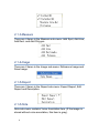
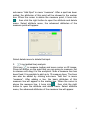
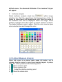
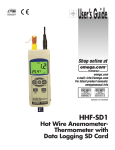
User’s Guide
SM
Extended Warranty
Program
Shop online at
OSXL160
IRSee Software
Version. 2.0
omega.com
e-mail: [email protected]
For latest product manuals:
omegamanual.info
System Requirements:
Windows 7/Windows XP
MADE IN CHINA
®
ENGINEERING, INC.
omega.com ®
800-TC-OMEGA (800-826-6342)
© COPYRIGHT 2011 OMEGA ENGINEERING, INC.
OSXL160
IRSee Software
OMEGAnet ® Online Service
omega.com
Internet e-mail
[email protected]
Servicing North America:
U.S.A.:
ISO 9001 Certified
Canada:
Omega Engineering, Inc., One Omega Drive, P.O. Box 4047
Stamford, CT 06907-0047 USA
Toll Free: 1-800-826-6342
TEL: (203) 359-1660
FAX: (203) 359-7700
e-mail: [email protected]
976 Bergar
Laval (Quebec), H7L 5A1 Canada
Toll-Free: 1-800-826-6342
FAX: (514) 856-6886
TEL: (514) 856-6928
e-mail: [email protected]
For immediate technical or application assistance:
U.S.A. and Canada: Sales Service: 1-800-826-6342/1-800-TC-OMEGA®
Customer Service: 1-800-622-2378/1-800-622-BEST®
Engineering Service: 1-800-872-9436/1-800-USA-WHEN®
Mexico/
Latin America:
En Español: 001 (203) 359-7803
[email protected]
FAX: 001 (203) 359-7807
e-mail: [email protected]
Servicing Europe:
Benelux:
Managed by the United Kingdom Office
Toll-Free: 0800 099 3344
TEL: +31 20 347 21 21
FAX: +31 20 643 46 43
e-mail: [email protected]
Czech Republic:
Frystatska 184
733 01 Karviná, Czech Republic
Toll-Free: 0800-1-66342
FAX: +420-59-6311114
France:
TEL: +420-59-6311899
e-mail: [email protected]
Managed by the United Kingdom Office
Toll-Free: 0800 466 342
TEL: +33 (0) 161 37 29 00
FAX: +33 (0) 130 57 54 27
e-mail: [email protected]
Germany/Austria: Daimlerstrasse 26
D-75392 Deckenpfronn, Germany
Toll-Free: 0800 6397678
FAX: +49 (0) 7056 9398-29
United Kingdom:
ISO 9001 Certified
TEL: +49 (0) 7056 9398-0
e-mail: [email protected]
OMEGA Engineering Ltd.
One Omega Drive, River Bend Technology Centre, Northbank
Irlam, Manchester M44 5BD United Kingdom
Toll-Free: 0800-488-488
TEL: +44 (0) 161 777-6611
FAX: +44 (0) 161 777-6622
e-mail: [email protected]
It is the policy of OMEGA Engineering, Inc. to comply with all worldwide safety and EMC/EMI
regulations that apply. OMEGA is constantly pursuing certification of its products to the European New
Approach Directives. OMEGA will add the CE mark to every appropriate device upon certification.
The information contained in this document is believed to be correct, but OMEGA accepts no liability for any
errors it contains, and reserves the right to alter specifications without notice.
WARNING: These products are not designed for use in, and should not be used for, human applications.
OSXL160
IRSee Software
User Manual
Please read carefully before first use
Contents
1.Software Installation ................................................... 1
Welcome to Use IRSee Report ...................................... 1
1.1 Introduction ................................................................. 1
1.2 System Requirements ............................................... 1
1.2.1 Hardware Requirements .................................. 1
1.2.2 Operating System Requirements.................... 1
1.3 Software Installation .................................................. 1
1.4 Starting-up Software.................................................. 4
2. IRSee Report User Interface...................................... 5
2.1 Main Menu and Toolbar ............................................ 5
2.1.1 File ....................................................................... 5
2.1.2 View..................................................................... 5
2.1.3 Measure.............................................................. 6
2.1.4 Image .................................................................. 6
2.1.5 Report ................................................................. 6
2.1.6 Note ..................................................................... 6
2.1.7 Temperature....................................................... 7
2.1.8 Window ............................................................... 7
2.1.9 Toolbar................................................................ 7
3.IRSee Report Introduction.......................................... 8
3.1 Add IR Image.............................................................. 8
3.2 Analyze IR Image....................................................... 8
3.2.1 Establish Analysis ............................................. 8
3.2.2 Adjust Measure Analysis................................ 12
3.3 Histogram .................................................................. 13
3.4 Save IR Image and add Reference....................... 13
3.5 Voice Annotation Playback..................................... 14
3.6 Temperature ............................................................. 14
3.7 Window ...................................................................... 14
4. Image Adjustment ................................................ 15
5. Report ................................................................... 15
i
1. Software Installation
Welcome to Use IRSee Report
1.1 Introduction
This IRSee Report version has a friendly user interface, 4
methods for measure analysis, and the function to save analysis
report in Microsoft Word format.
1.2 System Requirements
The files of the IRSee Report consist of IR image, visible light
(photo) and graphic file, all of which are far bigger than normal
text files, thus the following standards of the computer hardware
configuration should be met:
1.2.1 Hardware Requirements
z
z
z
z
CPU PENTIUM III with 1.4 GHz processor or faster
256 MB RAM or above
HD space above 20GB
Screen resolution above 1024 x 768
1.2.2 Operating System Requirements
IRSee Report is compatible with Microsoft Windows 2000, XP, or
Vista. It provides a multi-language version for users.
1.3 Software Installation
The instructions of IRSee Report installation and necessary
precautions before using this software will be given in detail
hereinafter:
1
Please follow the instructions when installing IR Analysis software
application. Place software CD-ROM into CD drive, and run
setup.exe in the CD root directory.
The default route is C:\Program Files\ IRSee Report. You can
change directory when installing.
Attention: users who are operating Vista please close user
account control to prevent warning.
z
After running setup.exe, the system shows a welcome
interface.
Select Next,
the system shows the default route. Press Browse to change
the route.
2
Select Next, the system will copy IRSee Report into PC. Or
select Back
Select Finish to confirm installation.
3
1.4 Starting-up Software
The following icon appears on Windows desktop after installing
IRSee Report.
Double click the icon to startup IRSee Report.
Open an image by menu: file/open or icon
4
in the toolbar.
Select a working language by menu: view/ Language.
IR Analysis software has 10 different working languages, namely:
English, Italian, Chinese (simplified & traditional), Japanese,
Russian, French, German, Korean, Spanish and Portuguese.
After selecting a language, a dialog box appears. Press YES to
confirm.
2. IRSee Report User Interface
IRSee Report is a standard Windows application and compatible
with Windows 2000, XP, and Vista. It supports all common
Windows operations.
2.1 Main Menu and Toolbar
There are 8 items in the main menu, namely: File, View, Measure,
Image, Report, Note, Temperature, and window.
2.1.1 File
There are 4 items in File sub-menu: New, Open, Close and Exit.
2.1.2 View
There are 4 items in View sub-menu: Toolbar, Status Bar, Line
Measure and Histogram.
5
2.1.3 Measure
There are 4 items in the Measure sub-menu: Add Spot, Add Line,
Add Rect. and Add Polygon.
2.1.4 Image
There are 2 items in the Image sub-menu: Reference Image and
Save Image.
2.1.5 Report
There are 3 items in the Report sub-menu: Export Report, Edit
Report and Description.
2.1.6 Note
Note sub-menu contains Voice Annotation item. (If the image is
stored without voice annotation, this item is gray).
6
2.1.7 Temperature
There are 2 items in this sub-menu: Celsius and Fahrenheit.
2.1.8 Window
There are 3 items in this sub-menu: new, cascade and tile.
2.1.9 Toolbar
7
3. IRSee Report Introduction
3.1 Add IR Image
Click button
in the toolbar or “File/open” to add an IR image.
If there are more than one image in one folder, use
button to select an image.
or
3.2 Analyze IR Image
3.2.1 Establish Analysis
Add an IR image to analyze it. There are 4 analysis methods:
Spot, Line, Area and Irregular Polygon analysis. The result
displays in the Marker box.
1.
Spot (added spot) analysis
in measure toolbar and move cursor on IR image.
Click icon
Click left button on the spot that you are going to measure. Now
the measure spots added in the IR image. It is possible to add up
to 20 measure spots. The spots also can be added by clicking
8
sub-menu “Add Spot” in menu “measure”. After a spot has been
added, the attributes of this point will be showed in the marker
box. When the cursor is above the measure point, it turns into
ˈ then click the right button to open the attribute and delete
menu. Select attribute menu, the advanced attributes of the
measure point will appear.
Select delete menu to delete that spot.
2.
Line (added line) analysis
in measure toolbar and move cursor on IR image.
Click icon
Press left button on the point that you are going to measure, not
to release until drag it to the end-point. Now a measure line has
been fixed. It is possible to add up to 10 measure lines. The lines
can also be added by clicking sub-menu “Add line” in menu
“measure”. After adding a line, the basic attributes of this
measure line will appear in the marker box. When the cursor is
ˈ then click the right
above the measure line, it turns into
button to open the attribute and delete menu. Select attribute
menu, the advanced attributes of the measure line will appear.
9
Select
display
highest/lowest
temperature
item,
the
maximum/minimum temperature will be showed in the measure
line. (icon γ denotes the maximum temperature and icon+
denotes the minimum temperature) Select delete menu to delete
that measure line.
If you want to get a visualized picture of the temperature trend of
the measure line, click “Line Measure” in sub-menu “View”.
When the cursor is on the black vertical line, it turns into , click
left button, not to release to drag the black vertical line and
change the cursor position accordingly.
Area (added Area) analysis
3.
10
Click icon
on measure toolbar and move cursor on IR image.
Press left button on the point that you are going to measure, not
to release until drag it to the end-point. Now an area has been
fixed. Up to 20 areas can be added. The areas can also be added
by clicking “Add area” in menu “Measure”. After an area has been
added, the attributes of this area will be showed in the marker box.
ˈ
When the cursor is inside the measure area, it turns into
then click the right button to open the attribute and delete menu.
Select attribute menu, the advanced attributes of the measure
area will appear.
Select “display highest/lowest temperature” item, the
maximum/minimum temperature will be showed in the measure
area. (icon γ denotes the maximum temperature and icon+
denotes the minimum temperature) Select delete menu to delete
that measure area.
Irregular Polygon (added Irregular Polygon) analysis
4.
on measure toolbar and move cursor on IR image.
Click icon
Click left button to fix the borderline of the Polygon, click right
button to confirm it. Up to 10 measure Polygons can be added.
The Polygons can also be added by clicking sub-menu “Add
Polygon” in menu “Measure”. After a Polygon has been added,
the attributes of this Polygon will be showed in the marker box.
ˈ
When the cursor is inside the measure Polygon, it turns into
click the right button to open the attribute and delete menu. Select
11
attribute menu, the advanced attributes of the measure Polygon
will appear.
5.
Isotherm analysis
within image
Select isotherm analysis check box
selection box. Set the upper/lower limit temperature of the IR
image by upper/lower limit temperature slide. Now the range of
the isotherm color will be displayed within the image. Press
isotherm analysis check box again to cancel isotherm analysis.
The default isotherm color is green. Click the color zone to open
color selection box and change the color.
3.2.2 Adjust Measure Analysis
When the cursor is in pickup state, press left button, not to
release, drag the cursor to move those analysis targets. In pickup
state, the cursor possesses the following forms:
Move measure spot.
1.
Move measure line.
2.
3.
Adjust the starting (ending) point.
4.
Move the whole area.
12
5. Adjust area. Select the measure area you are going to adjust,
click left button and 8 hot spots appear, drag those hot spots to
adjust the area size.
Move the whole polygon.
6.
7.
Adjust Polygon.
3.3 Histogram
The histogram shows the statistical information of the current
image temperature. When adjusting the temperature slide bar in
main window, the histogram changes accordingly. It is also
possible to change the histogram color by adjusting the
temperature slide bar in the histogram dialog box.
You can change the number of the current column in the
histogram by adjusting button
.
The functions of the buttons in the toolbar are as follow (from left
to right):
1. The ordinate switches between percentage and absolute
number.
2. The histogram color switches between gradual change and
consistency in red.
3. Switches between to show gridding background and not.
4. Save histogram as image in any format in common use.
5. Change histogram background color.
6. Switches between to show the exceeding column and not.
7. Reset the histogram as initial state.
3.4 Save IR Image and add Reference
Click reference image under image menu to open a box showed
in the following picture and add a visible light image:
13
Click “add image” button to add an image; Click “remove image”
button to delete an image. If a visible light image has been added,
it will be showed automatically in the report.
After finishing IR image analysis, click “save image” in image
menu to open the following box:
3.5 Voice Annotation Playback
If the IR image contains voice annotation data, the audio button
in measure toolbar is in active state, otherwise, it is in inactive
state (gray). Click this icon to open the voice dialog box. Click
play, pause, continue and stop to operate the voice record.
3.6 Temperature
Click pull-down menu Celsius/Fahrenheit in Temperature menu to
switch between Celsius and Fahrenheit. The default is Celsius.
3.7 Window
There are 3 sub-menus in the Window menu: new, cascade and
tile.
14
4. Image Adjustment
Click the pull-down menu at the right of “color palette”. There are
12 different color codes. The image will show in different color
according to different color code.
The slide bar below the image denotes the temperature the
camera has been set when taking IR images. The two ends of the
slide bar denote the upper/lower limit temperature of the color
code. Adjust upper/lower limit width of the color code to change
the image color.
5. Report
1. Edit Report
Click Edit Report sub-menu in Report menu to open edit dialog
box.
Filling in company name, company address and inspector name
in the form, click right button in the blank area of the LOGO line to
open add/delete image dialog box by using which User can
add/delete image. After filling, a user-defined report header is
created.
2. Description
Click Description submenu in Report menu to open Edit dialog
box.
15
The items hereinabove will be exported automatically in the
report.
3. Export report
Two kinds of reports can be exported: the default report and the
user-defined report. The default report contains information
header of OMEGA company. If end-users need header that
contains your own corporate information, please edit the report
and export that report.
The saving route of the document can be changed. After clicking
save button, the IR Analysis software will create a Word report
automatically. If reference image is not selected, the report
contains the following data: IR image, target parameter form,
result analysis form (which contains spot temperature, the
maximum/ minimum temperature of the line or the area),
temperature trend picture of line measure and histogram etc.
16
17
If reference image is selected, and the image has been added,
the report contains the following data: IR image, visible light
image, target parameter form, result analysis form (which
contains point temperature, the maximum/ minimum temperature
of the line or the area), temperature trend picture of line measure
and histogram etc.
18
19
If the computer has been installed with Microsoft Word software,
the reports can be edited in Word document.
20
WARRANTY/DISCLAIMER
OMEGA ENGINEERING, INC. warrants this unit to be free of defects in materials and workmanship for a
period of 13 months from date of purchase. OMEGA’s WARRANTY adds an additional one (1) month
grace period to the normal one (1) year product warranty to cover handling and shipping time. This
ensures that OMEGA’s customers receive maximum coverage on each product.
If the unit malfunctions, it must be returned to the factory for evaluation. OMEGA’s Customer Service
Department will issue an Authorized Return (AR) number immediately upon phone or written request.
Upon examination by OMEGA, if the unit is found to be defective, it will be repaired or replaced at no
charge. OMEGA’s WARRANTY does not apply to defects resulting from any action of the purchaser,
including but not limited to mishandling, improper interfacing, operation outside of design limits,
improper repair, or unauthorized modification. This WARRANTY is VOID if the unit shows evidence of
having been tampered with or shows evidence of having been damaged as a result of excessive corrosion;
or current, heat, moisture or vibration; improper specification; misapplication; misuse or other operating
conditions outside of OMEGA’s control. Components in which wear is not warranted, include but are not
limited to contact points, fuses, and triacs.
OMEGA is pleased to offer suggestions on the use of its various products. However,
OMEGA neither assumes responsibility for any omissions or errors nor assumes liability for any
damages that result from the use of its products in accordance with information provided by
OMEGA, either verbal or written. OMEGA warrants only that the parts manufactured by the
company will be as specified and free of defects. OMEGA MAKES NO OTHER WARRANTIES OR
REPRESENTATIONS OF ANY KIND WHATSOEVER, EXPRESSED OR IMPLIED, EXCEPT THAT OF
TITLE, AND ALL IMPLIED WARRANTIES INCLUDING ANY WARRANTY OF MERCHANTABILITY
AND FITNESS FOR A PARTICULAR PURPOSE ARE HEREBY DISCLAIMED. LIMITATION OF
LIABILITY: The remedies of purchaser set forth herein are exclusive, and the total liability of
OMEGA with respect to this order, whether based on contract, warranty, negligence,
indemnification, strict liability or otherwise, shall not exceed the purchase price of the
component upon which liability is based. In no event shall OMEGA be liable for
consequential, incidental or special damages.
CONDITIONS: Equipment sold by OMEGA is not intended to be used, nor shall it be used: (1) as a “Basic
Component” under 10 CFR 21 (NRC), used in or with any nuclear installation or activity; or (2) in medical
applications or used on humans. Should any Product(s) be used in or with any nuclear installation or
activity, medical application, used on humans, or misused in any way, OMEGA assumes no responsibility
as set forth in our basic WARRANTY/DISCLAIMER language, and, additionally, purchaser will indemnify
OMEGA and hold OMEGA harmless from any liability or damage whatsoever arising out of the use of the
Product(s) in such a manner.
RETURN REQUESTS/INQUIRIES
Direct all warranty and repair requests/inquiries to the OMEGA Customer Service Department. BEFORE
RETURNING ANY PRODUCT(S) TO OMEGA, PURCHASER MUST OBTAIN AN AUTHORIZED RETURN
(AR) NUMBER FROM OMEGA’S CUSTOMER SERVICE DEPARTMENT (IN ORDER TO AVOID
PROCESSING DELAYS). The assigned AR number should then be marked on the outside of the return
package and on any correspondence.
The purchaser is responsible for shipping charges, freight, insurance and proper packaging to prevent
breakage in transit.
FOR WARRANTY RETURNS, please have the
following information available BEFORE
contacting OMEGA:
1. Purchase Order number under which the product
was PURCHASED,
2. Model and serial number of the product under
warranty, and
3. Repair instructions and/or specific problems
relative to the product.
FOR NON-WARRANTY REPAIRS, consult OMEGA
for current repair charges. Have the following
information available BEFORE contacting OMEGA:
1. Purchase Order number to cover the COST
of the repair,
2. Model and serial number of the product, and
3. Repair instructions and/or specific problems
relative to the product.
OMEGA’s policy is to make running changes, not model changes, whenever an improvement is possible. This affords
our customers the latest in technology and engineering.
OMEGA is a registered trademark of OMEGA ENGINEERING, INC.
© Copyright 2011 OMEGA ENGINEERING, INC. All rights reserved. This document may not be copied, photocopied,
reproduced, translated, or reduced to any electronic medium or machine-readable form, in whole or in part, without the
prior written consent of OMEGA ENGINEERING, INC.
Where Do I Find Everything I Need for
Process Measurement and Control?
OMEGA…Of Course!
Shop online at omega.com SM
TEMPERATURE
䡺
⻬
䡺
⻬
䡺
⻬
䡺
⻬
䡺
⻬
Thermocouple, RTD & Thermistor Probes, Connectors, Panels & Assemblies
Wire: Thermocouple, RTD & Thermistor
Calibrators & Ice Point References
Recorders, Controllers & Process Monitors
Infrared Pyrometers
PRESSURE, STRAIN AND FORCE
䡺
⻬
䡺
⻬
䡺
⻬
䡺
⻬
Transducers & Strain Gages
Load Cells & Pressure Gages
Displacement Transducers
Instrumentation & Accessories
FLOW/LEVEL
䡺
⻬
䡺
⻬
䡺
⻬
䡺
⻬
Rotameters, Gas Mass Flowmeters & Flow Computers
Air Velocity Indicators
Turbine/Paddlewheel Systems
Totalizers & Batch Controllers
pH/CONDUCTIVITY
䡺
⻬
䡺
⻬
䡺
⻬
䡺
⻬
pH Electrodes, Testers & Accessories
Benchtop/Laboratory Meters
Controllers, Calibrators, Simulators & Pumps
Industrial pH & Conductivity Equipment
DATA ACQUISITION
䡺
⻬
䡺
⻬
䡺
⻬
䡺
⻬
䡺
⻬
Data Acquisition & Engineering Software
Communications-Based Acquisition Systems
Plug-in Cards for Apple, IBM & Compatibles
Data Logging Systems
Recorders, Printers & Plotters
HEATERS
䡺
⻬
䡺
⻬
䡺
⻬
䡺
⻬
䡺
⻬
Heating Cable
Cartridge & Strip Heaters
Immersion & Band Heaters
Flexible Heaters
Laboratory Heaters
ENVIRONMENTAL
MONITORING AND CONTROL
䡺
⻬
䡺
⻬
䡺
⻬
䡺
⻬
䡺
⻬
䡺
⻬
Metering & Control Instrumentation
Refractometers
Pumps & Tubing
Air, Soil & Water Monitors
Industrial Water & Wastewater Treatment
pH, Conductivity & Dissolved Oxygen Instruments
M5046/0711