1
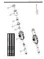
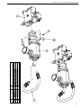
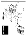
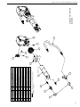
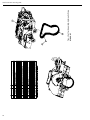
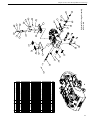
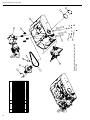
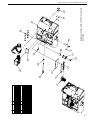
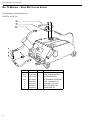
TRAV-L-CUTTER MODEL E & H/E STANDARD & ATMOSPHERIC 02-000-01,-02,-03,-04 E.H. Wachs 600 Knightsbridge Parkway Lincolnshire, IL 60069 www.ehwachs.com E.H. Wachs Part No. 02-MAN-01 Rev. A, March 2014 Copyright © 2014 E.H. Wachs. All rights reserved. This manual may not be reproduced in whole or in part without the written consent of E.H. Wachs. EU Declaration OF CONFORMITY WITH COUNCIL DIRECTIVE 2006/42/EC Issue Details: Directives: DATE: Place: 1/1/2011 E.H.Wachs, Lincolnshire, IL USA Machinery Safety Directive 2006/42/EC Conforming Machinery: Trav-L-Cutter: Model Number: 02-000-01, 02-000-02 Serial Number: Manufacturer: E.H. Wachs 600 Knightsbridge Parkway Lincolnshire IL 60069 USA Responsible Representative: Orbitalum Tools GmbH Josef-Schüttler-Str. 17, 78224 Singen Germany Tel. +49 (0) 7731 - 792 872 Fax +49 (0) 7731 - 792 566 Harmonised Standards & EN ISO 12100-1:2003 + A1:2009 Other Technical EN ISO 12100-2:2003 + A1:2009 Standards/Specifications EN 60201-1:2006 (for electric machines) Applied or Referenced: EN ISO 13857:2008 EN 982:1996 + A1:2008 (E) (for hydrailic machines) EN 983:1996 (for pneumatic machines) EN 13732-1:2006 EN ISO 14121-1:2007 EN ISO 13850:2008 (for pneumatic machines) Essential Health and Safety Requirements of Annex 1 of the Provisions with which Conformity is Declared: Machinery Directive We hereby certify that the machinery descrived above conforms to the provisions of Council Directive 2006/42/EC on the approximation of the laws of the Member States relating to the safety of machinery. Signed: Signatory: Pete Mullally Quality Manager E.H. Wachs Table of Contents Table of Contents Chapter 1: Introduction to the Equipment. . . . . . . . . . . . . . . . . . . . . . . . . . . . . . . . . . . . . . . . . . 1 Purpose of This Manual . . . . . . . . . . . . . . . . . . . . . . . . . . . . . . . . . . . . . . . . . . . . . . . . . . . . . . . . . . 1 How to Use The Manual. . . . . . . . . . . . . . . . . . . . . . . . . . . . . . . . . . . . . . . . . . . . . . . . . . . . . . . . . . 1 Symbols and Warnings . . . . . . . . . . . . . . . . . . . . . . . . . . . . . . . . . . . . . . . . . . . . . . . . . . . . . . . . . . . 2 Manual Updates and Revision Tracking. . . . . . . . . . . . . . . . . . . . . . . . . . . . . . . . . . . . . . . . . . . . . . 3 Equipment Description. . . . . . . . . . . . . . . . . . . . . . . . . . . . . . . . . . . . . . . . . . . . . . . . . . . . . . . . . . . 3 Compact Design, Easy Set-up . . . . . . . . . . . . . . . . . . . . . . . . . . . . . . . . . . . . . . . . . . . . . . 3 Standard Weld Prep Capability . . . . . . . . . . . . . . . . . . . . . . . . . . . . . . . . . . . . . . . . . . . . . . 3 Grooved, Mechanical Joint Preparation . . . . . . . . . . . . . . . . . . . . . . . . . . . . . . . . . . . . . . . 3 Offshore or Pipe Line Maintenance . . . . . . . . . . . . . . . . . . . . . . . . . . . . . . . . . . . . . . . . . . 3 Corrosion Resistant . . . . . . . . . . . . . . . . . . . . . . . . . . . . . . . . . . . . . . . . . . . . . . . . . . . . . . 4 Operates Anywhere . . . . . . . . . . . . . . . . . . . . . . . . . . . . . . . . . . . . . . . . . . . . . . . . . . . . . . 4 Safe, Cold Cutting . . . . . . . . . . . . . . . . . . . . . . . . . . . . . . . . . . . . . . . . . . . . . . . . . . . . . . . 4 Fast, Reliable . . . . . . . . . . . . . . . . . . . . . . . . . . . . . . . . . . . . . . . . . . . . . . . . . . . . . . . . . . . 4 Chapter 2: Safety. . . . . . . . . . . . . . . . . . . . . . . . . . . . . . . . . . . . . . . . . . . . . . . . . . . . . . . . . . . . . . . 5 Safe Operating Guidelines. . . . . . . . . . . . . . . . . . . . . . . . . . . . . . . . . . . . . . . . . . . . . . . . . . . . . . . . 5 Safe Operating Environment. . . . . . . . . . . . . . . . . . . . . . . . . . . . . . . . . . . . . . . . . . . . . . . . . . . . 6 Operating and Maintenance Safety. . . . . . . . . . . . . . . . . . . . . . . . . . . . . . . . . . . . . . . . . . . . . . . 6 Safety Alerts in This Manual. . . . . . . . . . . . . . . . . . . . . . . . . . . . . . . . . . . . . . . . . . . . . . . . . . . . 6 Protective Equipment Requirements. . . . . . . . . . . . . . . . . . . . . . . . . . . . . . . . . . . . . . . . . . . . . . 7 Protective Clothing . . . . . . . . . . . . . . . . . . . . . . . . . . . . . . . . . . . . . . . . . . . . . . . . . . . . . . . 7 Eye Protection . . . . . . . . . . . . . . . . . . . . . . . . . . . . . . . . . . . . . . . . . . . . . . . . . . . . . . . . . . 7 Hearing Protection . . . . . . . . . . . . . . . . . . . . . . . . . . . . . . . . . . . . . . . . . . . . . . . . . . . . . . . 7 Chapter 3: Machine Specifications . . . . . . . . . . . . . . . . . . . . . . . . . . . . . . . . . . . . . . . . . . . . . . . . 9 Chapter 4: Setup and Operating Procedures . . . . . . . . . . . . . . . . . . . . . . . . . . . . . . . . . . . . . . . 15 Wheel Settings . . . . . . . . . . . . . . . . . . . . . . . . . . . . . . . . . . . . . . . . . . . . . . . . . . . . . . . . . . . . . . . . 15 Chain Lengths. . . . . . . . . . . . . . . . . . . . . . . . . . . . . . . . . . . . . . . . . . . . . . . . . . . . . . . . . . . . . . . . . 16 Wheel Settings and Chain Length. . . . . . . . . . . . . . . . . . . . . . . . . . . . . . . . . . . . . . . . . . . . . . . . . . 17 Chain Length Calculations . . . . . . . . . . . . . . . . . . . . . . . . . . . . . . . . . . . . . . . . . . . . . . . . . . . . 17 Machine Installation . . . . . . . . . . . . . . . . . . . . . . . . . . . . . . . . . . . . . . . . . . . . . . . . . . . . . . . . . . . . 18 Operating the Machine . . . . . . . . . . . . . . . . . . . . . . . . . . . . . . . . . . . . . . . . . . . . . . . . . . . . . . . . . . 20 Special Instructions for Assembling 2” Wide Drive Chain. . . . . . . . . . . . . . . . . . . . . . . . . . . . 21 Operating Hints . . . . . . . . . . . . . . . . . . . . . . . . . . . . . . . . . . . . . . . . . . . . . . . . . . . . . . . . 22 Chapter 5: Maintenance. . . . . . . . . . . . . . . . . . . . . . . . . . . . . . . . . . . . . . . . . . . . . . . . . . . . . . . . 23 Lubrication Instructions . . . . . . . . . . . . . . . . . . . . . . . . . . . . . . . . . . . . . . . . . . . . . . . . . . . . . . . . . 23 E.H. Wachs Part No. 02-MAN-01, Rev. Ai Small LCSF O.D. Tracking Slide Chapter 6: Consumable Select Chart . . . . . . . . . . . . . . . . . . . . . . . . . . . . . . . . . . . . . . . . . . . . . 25 Data on Cutter Size. . . . . . . . . . . . . . . . . . . . . . . . . . . . . . . . . . . . . . . . . . . . . . . . . . . . . . . . . . . . . 25 Cutters. . . . . . . . . . . . . . . . . . . . . . . . . . . . . . . . . . . . . . . . . . . . . . . . . . . . . . . . . . . . . . . . . . . . . . . 27 Chapter 7: Troubleshooting Problems. . . . . . . . . . . . . . . . . . . . . . . . . . . . . . . . . . . . . . . . . . . . . 29 Chapter 8: Parts Lists & Exploded View Drawings. . . . . . . . . . . . . . . . . . . . . . . . . . . . . . . . . . 31 ii Part No. 02-MAN-01, Rev. A E.H. Wachs Chapter 1, Introduction to the Equipment Chapter 1 Introduction to the Equipment Purpose of This Manual This manual explains how to operate and maintain the Trav-L-Cutter. It includes instructions for set-up, operation, and maintenance. It also contains parts lists and diagrams, and troubleshooting instructions to help you order replacement parts and perform user-serviceable repairs. How to Use The Manual This manual is organized to help you quickly find the information you need. Each chapter describes a specific topic on using or maintaining your equipment. Use these instructions to operate and maintain the equipment. E.H. Wachs Part No. 02-MAN-01, Rev. A1 Small LCSF O.D. Tracking Slide Symbols and Warnings The following symbols are used throughout this manual to indicate special notes and warnings. They appear in the outside column of the page, next to the section they refer to. Make sure you understand what each symbol means, and follow all instructions for cautions and warnings. This is the safety alert symbol. It is used to alert you to potential personal injury hazards. Obey all safety messages that follow this symbol to avoid possible injury or death. WARNING A WARNING alert with the safety alert symbol indicates a potentially hazardous situation that could result in serious injury or death. CAUTION A CAUTION alert with the safety alert symbol indicates a potentially hazardous situation that could result in minor or moderate injury. A CAUTION alert with the damage alert symbol indicates a situation that will result in damage to the equipment. This is the equipment damage alert symbol. It is used to alert you to potential equipment damage situations. Obey all messages that follow this symbol to avoid damaging the equipment or workpiece on which it is operating. IMPORTANT An IMPORTANT alert with the damage alert symbol indicates a situation that may result in damage to the equipment. NOTE This symbol indicates a user note. Notes provide additional information to supplement the instructions, or tips for easier operation. 2 Part No. 02-MAN-01, Rev. A E.H. Wachs Chapter 1, Introduction to the Equipment: Manual Updates and Revision Tracking Manual Updates and Revision Tracking Occasionally, we will update manuals with improved operation or maintenance procedures, or with corrections if necessary. When a manual is revised, we will update the revision history on the title page. Current versions of E.H. Wachs Company manuals are also available in PDF format. You can request an electronic copy of this manual by emailing customer service at [email protected]. You may have factory service or upgrades performed on the equipment. If this service changes any technical data or operation and maintenance procedures, we will include a revised manual when we return the equipment to you. Equipment Description Compact Design, Easy Set-up Lightweight, low profile design needs only 10” to 12” of clearance and set up time is ten minutes or less. Once the adjustable drive chain is pinned together and tensioned around the pipe the machine is ready to operate. Standard Weld Prep Capability Weld preparation detail can be achieved from common 30º and 37-1/2º bevel on standard wall carbon steel. Grooved, Mechanical Joint Preparation The Trav-L-Cutter can simultaneously cut off and groove pipe in one cut. Cutters are available for Victaulic and other grooved coupling systems. Offshore or Pipe Line Maintenance The Wachs Hydraulic Trav-L-Cutter offers the inherent advantages of a completely sealed and self-lubricating closed loop system. The Model HE is particularly suited to field machining operations under the type of hostile conditions often found in pipe line maintenance and construction such as dirt, sand and water. It is a portable pipe cutting machine that can be used conveniently on offshore drilling rigs, pipe lines and on construction work in rivers and harbors. E.H. Wachs Part No. 02-MAN-01, Rev. A3 Small LCSF O.D. Tracking Slide Corrosion Resistant Corrosion from constant exposure to salt water can be minimized with an accessory package that includes extensive use of stainless steel fasteners, special bearings and seals and high zinc coating. Operates Anywhere With air or hydraulic power, the Trav-L-Cutter will operate on horizontal or vertical pipe, in the field or in the shop. It cuts and bevels in a mud filled ditch or under water, where it has been used in chambers and free diving to depths of 600 feet. Safe, Cold Cutting The Trav-L-Cutter can be used in explosive conditions, onnatural gas, crude, product and fuel lines. It has even been used to cut missile fuel cells. Fast, Reliable A standard wall pipe can be cut and beveled with a cutting speed of approximately 2 minutes per 1” of pipe diameter. Cutting time varies for heavier walls and harder alloys. Due to its rugged construction, it is not unusual to find machines still operating after 10 or 20 years of severe service. Included with your TRAV-L-CUTTER: • • • • 4 Operating Manual and Isometric Parts List, Operating Tools, and spare Chain Connecting Pins. Basic Mounting Chain for 6” dia. pipe Steel Storage Case 6-ft. Hose Whip with oiler (air only) Part No. 02-MAN-01, Rev. A E.H. Wachs Chapter 2, Safety Chapter 2 Safety E.H. Wachs takes great pride in designing and manufacturing safe, high-quality products. We make user safety a top priority in the design of all our products. Read this chapter carefully before operating the bridge slide. It contains important safety instructions and recommendations. FULL SAFETY INSTRUCTIONS AND GUIDELINES ARE IN THE MANUAL FOR YOUR Trav-L-Cutter MACHINE. Make sure you read and understand these safety recommendations and operating instructions before operating. Safe Operating Guidelines Follow these guidelines for safe operation of all E.H. Wachs equipment. Look for this symbol throughout the manual. It indicates a personal injury hazard. • READ THE OPERATING MANUAL. Make sure you understand all setup and operating instructions before you begin. Keep this manual with the machine. • INSPECT MACHINE AND ACCESSORIES BEFORE USE. Before starting the machine, look for loose bolts or nuts, leaking lubricant, rusted components, and any other physical conditions that may affect operation. Properly maintaining the machine can greatly decrease the chances for injury. • ALWAYS READ STICKERS AND LABELS. Make sure all labels and stickers are in place, clearly legible, and in good condition. Refer to “Safety Labels” later in this chapter for label locations on the machine. Replace any damaged or missing safety labels; see the ordering information at the end of this manual. • KEEP CLEAR OF MOVING PARTS. Keep hands, arms, and fingers clear of all rotating or moving parts. Always turn the machine off and disconnect the power source before doing any adjustments or service. E.H. Wachs Part No. 02-MAN-01, Rev. A5 Small LCSF O.D. Tracking Slide • SECURE LOOSE CLOTHING AND JEWELRY. Secure or remove loose-fitting clothing and jewelry, and securely bind long hair, to prevent them from getting caught in moving parts of the machine. • FOLLOW SAFE PROCEDURES FOR HANDLING LUBRICANTS. Refer to the manufacturer’s instructions and the Material Safety Data Sheets. Safe Operating Environment • Do not use this equipment in a potentially explosive atmosphere. Fire or explosion could result, with the risk of serious injury or death. • Provide adequate lighting to use the equipment, in accordance with worksite or local regulations. • KEEP WORK AREA CLEAR. Keep all clutter and nonessential materials out of the work area. Only people directly involved with the work being performed should have access to the area. Operating and Maintenance Safety • This equipment is to be operated and maintained only by qualified, trained personnel. • Make sure the equipment is stable when attached to the workpiece for the operation. Ensuring stability of the installed tool is the responsibility of the operator. • Make sure the workpiece is supported adequately for installation of the equipment. This includes supporting any workpiece “fall-off” section when severing the workpiece. Ensuring support of the workpiece is the responsibility of the operator. • Tooling on any cutting equipment—including lathe tools, saw blades, milling tools, etc.—may get very hot. Do not touch tooling until you have made sure it is cool enough to handle. • Wear gloves when removing or cleaning up chips and cutting debris. Chips can be very sharp and cause cuts. • Before performing any service on the equipment, disconnect the power source. Follow all lock-out/tag-out procedures required at the worksite. Safety Alerts in This Manual The following alerts are used throughout this manual to indicate operator safety hazards. In all cases, these alerts include a notice describing the hazard and the means to avoid or reduce risk. Carefully read all safety alerts. This icon is displayed with any safety alert that indicates a personal injury hazard. WARNING This safety alert, with the personal injury hazard symbol, indicates a potentially hazardous situation that, if not avoided, could result in death or serious injury. 6 Part No. 02-MAN-01, Rev. A E.H. Wachs Chapter 2, Safety: Safe Operating Guidelines CAUTION This safety alert, with the personal injury hazard symbol, indicates a potentially hazardous situation that, if not avoided, could result in minor or moderate injury. Protective Equipment Requirements Protective Clothing Wear safety shoes when operating or servicing the equipment. Serious injury could result from dropping the machine or its components. Do not wear gloves while operating the machine. Gloves can become entangled in moving parts, resulting in serious injury. Gloves may be worn when setting up the machine or cleaning up after the operation, but take them off when operating the machine. NOTE Gloves should be worn when cleaning up chips and other cutting debris. Chips can be very sharp and can cause serious cuts. Do not wear gloves when the machine is operating. Eye Protection Always wear impact-resistant eye protection while operating or working near this equipment. For additional information on eye and face protection, refer to Federal OSHA regulations, 29 Code of Federal Regulations, Section 1910.133., Eye and Face Protection and American National Standards Institute, ANSI Z87.1, Occupational and Educational Eye and Face Protection. Hearing Protection This equipment can produce noise levels above 80 dB. Hearing protection is required when operating the equipment. The operation of other tools and equipment in the area, reflective surfaces, process noises, and resonant structures can increase the noise level in the area. For additional information on hearing protection, refer to Federal OSHA regulations, 29 Code of Federal Regulations, Section 1910.95, Occupational Noise Exposure and ANSI S12.6 Hearing Protectors. E.H. Wachs Part No. 02-MAN-01, Rev. A7 Small LCSF O.D. Tracking Slide 8 Part No. 02-MAN-01, Rev. A E.H. Wachs Chapter 3, About This Manual Chapter 3 Machine Specifications Capacity: 6” through 72” (153 to 1829 mm) pipe, large diameter vessels. All schedules. Cutter Drive: Pneumatic: 4 H.P. Governed Air Motor coupled with worm gearbox Hydraulic: As above, with hydraulic motor. Cutter Speed: Pneumatic: 55 R.P.M. Internally adjustable from 35 to 55 R.P.M. for use on alloys that might become work hardened. Hydraulic; Adjustable 0-60 R.P.M. E.H. Wachs Part No. 02-MAN-01, Rev. A9 Small LCSF O.D. Tracking Slide Feed: Pneumatic: 3/4 H.P. Air Motor coupled through overload clutch, gearbox and chain reduction to final machine drive sprocket. Hydraulic: 4 H.P. Hydraulic Motor. Feed Method: Positive, non-slip chain drive Air Requirements: 100 cfm @ 90 psi (2,832 l/min @ 6.3 bar) Hydraulic Requirements: 15 gpm @ 1500 psi. (57 l/min @ 106 bar) Clearance: 10” to 12” (254 to 305 mm) radial, depending on pipe diameter. 20” axial (508 mm) Weight: Operating - 215 lbs. (97.7 kgs) Shipping-(typical) - 418 lbs. (190 kg) Dimensions: Length: 24” (61 cm) Width: 20” (51 cm) Height: 10-3/4” (28 cm) Controls: (Pneumatic and Hydraulic): Cutter on-off, feed on-off, with interlock to prevent machine feed unless cutter is turning. Adjustable Feed Speed Control (Hydraulic Only) Flow Control Valves. Separate controls provide adjustable feed and cutter speed. Forward/Reverse Valve. Permits machine to be backed up. Shipping and Storage Cased: 41 “ x 25” x 18” (104 x 63.5 x 45.7 cm) 10.7 cu. ft. (0.53 m2) Finish: Paint Hose Assembles (Hydraulic): 5/8” hose sets with quick couplers, in 45’ lengths Hydraulic Power Sources (Model HE): - Electric, Gasoline or Diesel Engine driven. Gang of Cutters for Beveling Pipe 1 R.H. Bevel, 1 Slitting Saw, and 1 L.H. Bevel 10 Part No. 02-MAN-01, Rev. A E.H. Wachs 3.13 [79.4] MIN. 6.25 [158.8] MAX. BLADE TRAVEL 9.48 240.7 19.76 502 2.37 60.2 15.00 381 9.69 246 6.13 155.6 3.62 92 .50 12.7 22.00 558.8 10.31 262 29.72 REF 754.9 6.75 171.5 4.25 108.1 25.30 642.6 DIMENSIONS IN BRACKETS ARE MILLIMETERS .66 TYP 16.8 Operating Envelope Trav-L-Cutter Assembly, Air Drive 02-000-01 17.43 REF 442.8 CUT LINE 16.56 420.5 CUT LINE 15.12 384.2 Chapter 3, About This Manual: Machine Specifications 11 9 11 1 1 1 1 1 1 1 2 1 1 1 1 1 1 1 1 4 1 1 3 1 1 2 1 1 1 1 1 1 5 4 2 5 1 2 1 1 1 1 QTY. 3/4" FEMALE NPT INPUT 02-010-00 02-027-01 02-029-00 02-031-00 02-033-00 02-035-00 02-037-00 02-124-00 02-163-00 02-164-00 02-166-00 02-171-00 02-185-00 02-191-00 02-192-00 02-212-00 90-044-53 90-058-02 90-058-04 90-058-05 90-058-51 90-059-51 90-059-53 90-098-01 90-098-04 90-098-05 90-098-06 90-098-57 90-098-58 90-150-08 90-153-10 90-154-07 90-155-51 90-161-07 90-161-10 90-165-52 90-218-01 90-218-03 90-218-10 1 2 3 4 5 6 7 8 9 10 11 12 13 14 15 16 17 18 19 20 21 22 23 24 25 26 27 28 29 30 31 32 33 34 35 36 37 38 39 12 PART NUMBER ITEM DESCRIPTION SPINDLE MOTOR 3 2 5 LABEL, PRESSURE-AIR (NOT SHOWN) HOSE, 1/2" HP X 30" LONG AIR MOTOR SUB-ASSEMBLY HOSE, TRAVEL MOTOR MANIFOLD, AIR MOTOR, TRAVEL-AIR CLAMP, AIR MOTOR HANDLE, AIR VALVE BODY, AIR FILTER FILTER ELEMENT (NOT SHOWN) AIR LINE LUBRICATOR INLET AIR HOSE WHIP, 3/4" X 2" LABEL, ON-OFF (NOT SHOWN) SHIM, GEAR BOX (NOT SHOWN) END PLUG FLOW CONTROL VALVE 1/4" SSS, 10-32 X 5/16 CP (NOT SHOWN) NIPPLE, 1/4 X 5 GALV LP COUPLING, 1/4 GALV LP 1/4 NPT F X 1/4 NPT M BRASS LP-90 ADAPTER, 1/4 NPT M X 1/4 NPT F SWIVEL-45 DISCONNECT, FEMALE 1/4 NPT M DISCONNECT, MALE 1/4 NPT M NIPPLE, 1/2 CLOSE LP BLACK (NOT SHOWN) ELBOW, 1/2-45 STREET ELBOW, 1/2-90 STREET ELBOW, 1/2-90 LP ADAPTER, 1/2 NPT F X 1/2 NPT F SWIVEL-STRAIGHT 1/2 HEX HP NIPPLE (NOT SHOWN) SHCS, 1/4-20 X 7/8 SS18-8 FHCS, 1/4-20 X 1 SS18-8 (NOT SHOWN) SSS, 1/4-20 X 3/4 SS18-8 (NOT SHOWN) WASHER, 1/4" HI COLLAR SS18-8 HHCS, 5/16-18 X 5/8 SS18-8 HHCS, 5/16-18 X 1 SS18-8 (NOT SHOWN) WASHER, 5/16 FLAT SS18-8 NIPPLE, 3/4 CLOSE LP (NOT SHOWN) ELBOW, 3/4-45 LP STREET BUSHING, 1-1/4 X 3/4 GLV REDUCING 23 4 FEED MOTOR 6 16 23 22 9 2 11 3 30 33 39 26 15 38 36 25 34 7 5 8 20 23 4 20 18 6 21 19 20 16 22 95 CFM [2690 l/min.] 125 PSI [8.6 bar] MAX. INPUT REQUIREMENTS TRAV-L-CUTTER AIR SYSTEM COMPONENTS 12 28 27 26 Chapter 3, About This Manual: Machine Specifications 12 3.13 [79.4] MIN. 6.25 [158.8] MAX. BLADE TRAVEL 10.12 256.9 19.76 502 15.00 381 2.37 60.2 9.69 246 6.13 155.6 3.62 92 27.18 REF 690.2 22.00 558.8 6.75 171.5 4.25 108.1 26.07 662.1 10.31 262 1.35 REF 34.2 .66 TYP 16.8 Operating Envelope Trav-L-Cutter Assembly, Hydraulic Drive 02-000-02 18.28 REF 464.4 CUT LINE 16.56 420.5 CUT LINE 15.12 384.2 12.49 317.2 DIMENSIONS IN BRACKETS ARE MILLIMETERS Chapter 3, About This Manual: Machine Specifications 13 14 02-009-00 02-027-01 02-199-00 02-200-00 02-201-00 02-202-00 02-203-00 02-204-00 02-205-00 02-206-01 02-211-00 02-212-00 02-213-00 02-214-01 02-215-00 02-218-00 02-298-00 90-029-44 90-058-51 90-058-52 90-058-56 90-058-57 90-058-58 90-098-52 90-098-53 90-098-55 90-098-58 90-098-60 90-098-79 90-150-07 90-153-12 90-161-10 90-161-27 90-165-01 90-165-52 90-171-07 90-171-08 1 2 3 4 5 6 7 8 9 10 11 12 13 14 15 16 17 18 19 20 21 22 23 24 25 26 27 28 29 30 31 32 33 34 35 36 37 SPINDLE MOTOR 5 PART NUMBER ITEM 2 1 2 1 1 1 1 1 1 1 1 1 1 1 3 1 1 1 1 1 2 2 2 2 1 1 4 3 2 2 5 4 4 2 2 2 4 4 QTY. DESCRIPTION 2 11 1/2" MALE NPT INPUT/OUTPUT 15 LABEL, PRESSURE-HYD. (NOT SHOWN) HOSE, 1/2" HP X 30" LONG MOTOR COUPLING, DRIVE PIN HYDRAULIC MOTOR, CARRIAGE DRIVE HYDRAULIC MOTOR, CUTTER SPINDLE ADAPTER, CUTTER SPINDLE MOTOR COUPLING, MOTOR (NOT SHOWN) DRIVE MOTOR ADAPTER BRACKET, MOUNTING-DRIVE MOTOR SHIM, HYDRAULIC GEAR BOX (NOT SHOWN) 1/2" FLOW CONTROL VALVE FLOW CONTROL VALVE 1/4" 1/4" 4-WAY VALVE REVERSING 1/4" HP HOSE ASSEMBLY 1/2" ON/OFF VALVE MANIFOLD LABEL, TRAV-L-CUTTER HYD. (NOT SHOWN) KEY 1/8 X 1/2 #3 WOODRUFF (404) (NOT SHOWN) ADAPTER, 1/4 NPT M X 1/4 NPT F SWIVEL-45 ADAPTER, 1/4 NPT M X 1/4 NPT F SWIVEL-90 ELBOW, 1/4-90 HP STREET BUSHING, 1/2 X 1/4 HP REDUCING (NOT SHOWN) NIPPLE, 1/4 HEX H.P. NIPPLE, 1/2" X 2" SCH 80 A106 B NIPPLE, 1/2" X 2-1/2" SCH 80 A106 B ADAPTER, 1/2" NPT M X 1/2" NPT F SWIVEL-90 1/2 HEX HP NIPPLE ADAPTER, 1/2" NPT F X 1/2" NPT F-90 ADAPTER, 1/2 NPT M X 1/2 ORB M - STRAIGHT SHCS, 1/4-20 X 3/4, SS18-8 FHCS, 1/4-20 X 1-1/4 SS18-8 (NOT SHOWN) HHCS, 5/16-18 X 1 SS18-8 (NOT SHOWN) HHCS, 5/16-18 X 2-3/4 SS18-8 (NOT SHOWN) NUT, 5/16-18 HEX SS18-8 (NOT SHOWN) WASHER, 5/16 FLAT SS18-8 HHCS, 3/8-16 X 3/4 SS18-8 HHCS, 3/8-16 X 7/8 SS18-8 (NOT SHOWN) 16 14 12 4 FEED MOTOR 14 2 13 14 28 26 25 24 27 11 5 36 6 26 27 29 29 16 23 13 12 23 20 19 20 9 4 14 14 21 21 14 8 2000 PSI [138 bar] MAX. 15 GPM [57 L/MINUTE] INPUT REQUIREMENTS TRAV-L-CUTTER HYDRAULIC SYSTEM COMPONENTS 26 15 30 Small LCSF O.D. Tracking Slide Chapter 4, Setup and Operating Procedures Chapter 4 Setup and Operating Procedures Wheel Settings PIP E Ø 14.00” – 19.99” (356-508mm) M M AC AC HI HI NE NE TR TR AV E L AV E L PIP E Ø 6.00” – 13.99” (152-355mm) WHEEL POSITION 3 & 4 WHEEL POSITION 3 & 5 PIP E Ø 36.00” – 47.99” (914-1219mm) M AC M HI AC NE HI TR NE TR AV E L AV E L PIP E Ø 20.00” – 35.99” (508-914mm) WHEEL POSITION 2 & 5 WHEEL POSITION 2 & 6 M AC HI NE TR AV E L PIP E Ø 48.00” – 72.00” (1219-1829mm) WHEEL POSITION 1 & 6 E.H. Wachs Part No. 02-MAN-01, Rev. A15 Small LCSF O.D. Tracking Slide Chain Lengths PIPE SIZE 6” 8” 10” 12” 14” 16” 18” 20” 24” 30” 36” 42” 48” 54” 60” 72” TYPE DI/S¹ PIPE DIA. S 6.625” (168mm) Di 6.90” (175mm) S 8.625" (219mm) Di 9.05" (230mm) S 10.75" (273mm) Di 11.10" (282mm) S 12.75" (324mm) Di 13.20" (335mm) ADD ON LENGTH² PART NUMBER TOTAL LENGTH 0 02-457-06 42” (1067mm) ACCUMULATED CHAIN ASSEMBLIES N/A 5” (127mm) 02-457-08 47” (1194mm) 8” (203mm) 02-457-10 55” (1397mm) 02-450-10 6” (152mm) 02-457-12 61” (1549mm) 02-450-12 2” (51mm) 02-457-14 63” (1600mm) 02-450-14 6” (152mm) 02-457-16 69” (1752mm) 02-450-16 7” (179mm) 02-457-18 76” (1930mm) 02-450-18 S 14.00" (356mm) Di 15.30" (389mm) S 16.00" (406mm) Di 17.40" (442mm) S 18.00" (457mm) Di 19.50" (495mm) S 20.00" (508mm) 2" (51mm) 02-457-20 78" (1981mm) 02-450-20 Di 21.60" (549mm) 7" (179mm) 02-457-20-D 83" (2108mm) 02-450-20-D S 24.00" (610mm) 91" (2312mm) 02-450-24 Di 25.80" (655mm) S 30.00" (762mm) Di 32.00" (813mm) S 36.00" (915mm) Di 38.30" (973mm) S 42.00" (1067mm) 13” (330mm) 02-457-24 20” (508mm) 02-457-30 17” (432mm) 02-457-36 19” (482mm) 02-457-42 96" (2438mm) 111" (2819mm) 02-450-30 116" (2946mm) 128"(3251mm) 02-450-36 133" (3378mm) 147" (3734mm) 02-450-42 Di 44.50" (1130mm) S 48.00" (1219mm) 17" (432mm) 02-457-48 164" (4166mm) 02-450-48 Di 50.80" (1290mm) 21" (533mm) 02-457-48-D 173" (4394mm) 02-450-48-D S 54.00" (1372mm) Di 57.26" (1454mm) 20” (508mm) 02-457-54 152" (3861mm) 184" (4674mm) 194" (4928mm) 02-450-54 S 60.00" (1524mm) 18" (458mm) 02-457-60 202" (5131mm) 02-450-60 Di 61.61" (1565mm) 13" (330mm) 02-457-60-D 207" (5258mm) 02-450-60-D S 72.00" (1829mm) 38" (965mm) 02-457-72 240" (6096mm) 02-450-72 ¹ S - STEEL PIPE MEASUREMENTS - PER ASME B36.19M-2004 DI- DUCTILE-IRON PIPE MEASUREMENTS - PER ANSI/AWWA C151/A21.51-91 ² REQUIRES 42” (1067mm) BASE CHAIN AND ALL PREVIOUS ADD ON LENGTHS 16 Part No. 02-MAN-01, Rev. A E.H. Wachs Chapter 4, Setup and Operating Procedures: Wheel Settings and Chain Length E TR AV EL Wheel Settings and Chain Length M AC H IN WACHS TRAV-L-CUTTER STEEL WHEEL SETTINGS & CHAIN LENGTH PIPE DIAMETER 6” 8” 10” 12” 14” 16” 18” 20” 24” 30” 36” 42” 48” 54” 60” 72” ADD ON LENGTH IN MM 0 5 127 8 203 6 152 2 51 6 152 7 179 2 51 13 330 20 508 17 432 19 482 17 432 20 508 18 458 38 965 TOTAL IN MM 42 1067 47 1194 55 1397 61 1549 63 1600 69 1752 76 1930 78 1981 91 2312 111 2819 128 3251 147 3734 164 4166 184 4674 202 5131 240 6096 DUCTILE WHEEL POSITION 3&4 3&5 2&5 2&6 1&6 ADD ON LENGTH IN MM 0 5 127 8 203 6 152 2 51 6 152 7 179 7 179 13 330 20 508 17 432 19 482 21 533 20 508 13 330 X TOTAL IN MM 42 1067 47 1194 55 1397 61 1549 63 1600 69 1752 76 1930 83 2108 96 2438 116 2946 133 3378 152 3861 173 4394 194 4928 207 5258 X 6” 8” 10” 12” 14” 16” 18” 20” 24” 30” 36” 42” 48” 54” 60” 72” PIPE DIAMETER Chain Length Calculations You can calculate the required chain length for any size pipe using the following formulas. Pipe O.D. Wheel Positions Chain length Formula 6.0”-13.99” (168-355 mm) 3 and 4 3.235 x (Pipe Diameter in Inches) + 19.06” 3.235 x (Pipe Diameter in mm) + 484 mm 14”- 19.99” (356-507 mm) 3 and 5 3.204 x (Pipe Diameter in Inches) + 16.33” 3.204 x (Pipe Diameter in mm) + 415 mm 20”-35.99” 508-914 mm 2 and 5 3.175 x (Pipe Diameter in Inches) + 14.98” 3.175 x (Pipe Diameter in mm) + 380 mm 36”-47.99” (915-1218 mm) 2 and 6 3.162 x (Pipe Diameter in Inches) + 12.82” 3.162 x (Pipe Diameter in mm) + 326 mm 48”-72” (1219-1829 mm) 1 and 6 3.149 x (Pipe Diameter in Inches) + 12.61” 3.149 x (Pipe Diameter in mm) + 320 mm Note that there is some overlap in acceptable wheel positions between size ranges. E.H. Wachs Part No. 02-MAN-01, Rev. A17 Small LCSF O.D. Tracking Slide Machine Installation The Wachs Trav-L-Cutter (TLC) is shipped from the factory completely assembled and lubricated. It is only necessary to mount the machine, install the cutting wheel and connect the power supply. Please observe the following warning stickers located on the TLC before proceeding to operate machine. Figure 4-1. Machine Installation 1. Refer to the Section on Wheel Setting and Chain Lengths and determine the proper wheel position for the size of pipe to be cut. If the wheel assemblies are not in the proper slots, the eight 1/2” socket head cap screws (Part No. 90-090-17) shown in figure 1 should be removed and the wheel assemblies taken from the carriage.Place the wheel assemblies in the proper slots in the carriage. Make sure the protruding dowel pins (Part No. 90-076-20) are inserted in the dowel pin holes. Replace the eight 1/2” socket head cap screws and tighten securely. 2. Check and make sure the cutter spindle is in its uppermost position. To raise the cutter spindle, loosen the thumbscrew (Part No. 90-059-04) and slide feed screw lock (Part No. 02-008-00) back. With the aid of the socket wrench turn the feed screw in a counter clockwise direction until the cutter spindle is raised to its highest position. 3. From the Section on Wheel Setting and Chain Length, select the combination of chain segments to make up the required length of chain. Each segment of chain is marked for easy identification. 18 Part No. 02-MAN-01, Rev. A E.H. Wachs Chapter 4, Setup and Operating Procedures: Machine Installation Starting with the basic length of chain marked 6 (42” long section) add the necessary chain segments to make up the proper length. When assembling the segments of chain to the basic length be sure they are assembled male end to female end. Don’t try to join ends where numbers come together. The lengths of the chain will engage freely if they are clean. The chain segments are coupled with special chain connecting pins (Part No. 02-158-00) furnished with the chain. When connecting the chain segments it is best that they be placed on a flat surface to simplify the joining of the links. Use the lineup pin (Part No. 02-159-00) to get the joining links in proper alignment. When the chain links are aligned push the lineup pin out of the chain by inserting a connecting pin from the opposite side. 4. Turn the chain tension screw (Part No. 02-081-01) counter clockwise to move the chain tension idler sprocket to its innermost position. 5. Thread the assembled chain through the machine as shown in the section on Wheel Setting and Chain Length (inside cover). Leave six inches protruding on valve end of machine – balance of chain on other end. 6. Place the machine on the pipe and join the open ends of the chain with a connecting pin as shown in sketch for chain assembly (Figure 3, p. 16). To assist in getting chain square on pipe, rock machine after chain has been connected but before it has been tightened. CAUTION During chain connection, one person should hold cutter steady on pipe. Failure to do so could cause serious injury. 7. Tighten the chain by turning the chain tension screw in a clockwise direction. The chain will be properly tensioned when the torque wrench is applied to the chain tension screw and it registers 80 to 85 foot pounds (green line on torque wrench). 8. Recheck chain tension frequently on large diameter or heavy wall pipe cutting. 9. Remove lock nut (Part No. 02-014-00) and driving collar spacer (Part No. 02-022-01) cutter spindle. 10. Select the proper cutter from Cutter Chart on pages 20-21 and place cutter on cutter spindle. In as much as the cutter rotates in a clockwise direction as you face it, the cutter should be placed on the spindle so the flat, sharp cutting edges lead into the pipe. Place the driving collar spacer on the spindle and lock the spacer and cutter tightly to the spindle with the lock nut. E.H. Wachs Part No. 02-MAN-01, Rev. A19 Small LCSF O.D. Tracking Slide NOTE Left hand thread in nut turns counter clockwise to tighten. Be sure the cutter drive collar spacer and lock nut are clean and free of chips and dirt so that the assembly can be tightened securely. NOTE It is important to use sharp cutters. A dull cutter puts an unnecessary load on the machine and will result in unsatisfactory cuts. Cutters should be sharpened by a qualified tool grinder who has equipment to maintain the cutter angles and shape. A tool grinder who caters to machine shops or tool and die shops is best. Please contact your E.H. Wachs representative for further details regarding tool sharpening services. Operating the Machine 1. Connect the power supply to hose whip on Pipe Cutter. CAUTION Be sure the valves on the machine are off before supplying air to the machine. When the handles on air valves are up they are in the OFF position. 2. With the power supply turned on the machine is ready to cut the pipe. Turn the valve handle on Cutter Valve 90° to the right. This will put the cutter spindle motor in operation and rotate the cutter. 3. Slowly feed the rotating cutter down until it extends through the wall of the pipe by approximately 1/4”. This is done by turning the feed screw (Part No. 02-001-00) in a clockwise direction. One complete turn of the feed screw lowers the cutter 1/10”. Lock the cutter in position by placing the feed screw lock (Part No. 02-008-00) on the shoulder of the feed screw and lock in place with the thumb screw (Part No. 90-059-04). 4. Turn valve handle on Feed Valve 90° to the right. This will operate the drive motor and make the machine travel around the pipe and make a complete cut. Speed may be reduced by adjustment of the feed valve handle (close slowly until proper speed is attained). Machine is traveling too fast if wheel to right of cutter lifts off pipe or if machine is vibrating excessively. 5. When the cut is completed stop the drive motor by turning Feed Valve to the left until machine stops. With the cutter still rotating release the elevating screw lock and raise the cutter to its uppermost position. With the cutter raised, stop the cutter motor by turning Cutter Valve to the left 90°. Remove the cutter from the machine. Release the tension on the drive chain by turning the chain tension screw counter clockwise. Remove a connecting pin from the chain to uncouple it and the machine can now be removed from the pipe. 20 Part No. 02-MAN-01, Rev. A E.H. Wachs Chapter 4, Setup and Operating Procedures: Operating the Machine Special Instructions for Assembling 2” Wide Drive Chain As shown on the right, all sections of the chain have one female end and one male end. One outside link on the female end of the chain is stamped with the Chain Section Number. In assembling the chain, always start with the basic length marked 6 (42” long section) and add the required number of sections of chain, in the proper sequence, until the desired length is obtained. EXAMPLE: Assemble Chain for 12” pipe. Start with the basic length marked 6 and add to it, in sequence, the pieces marked 8, 10, & 12. If this chain is correctly assembled it will be the proper length to be threaded through the Trav-LCutter and wrapped around a 12” pipe as shown in the 1st picture under Wheel Settings and Chain Lengths on the inside front cover of this manual. STAMPED WITH CHAIN SECTION No. FEMALE END MALE END NOTE: To convert inches to centimeters multiply by 2.54 Figure 4-2. Assembling 2” Wide Drive Chain NOTE When cutting medium and large diameter thin wall steel pipe it may be found that the prescribed length of chain will be too long to be properly tensioned. If this is the case, remove a section of chain so that the total length will be of a size that can be properly tensioned. E.H. Wachs Part No. 02-MAN-01, Rev. A21 Small LCSF O.D. Tracking Slide WARNING ALWAYS CONNECT THE MALE END OF ONE SECTION TO THE FEMALE END OF THE SECTION OF CHAIN THAT PRECEDES IT. NEVER CONNECT TWO MALE ENDS OR TWO FEMALE ENDS OF CHAIN TOGETHER AS THIS WILL THROW THE CHAIN OUT OF LINE AND WILL CAUSE MALFUNCTION OF THE TRAV-LCUTTER AND CHAIN AND SPROCKET BREAKAGE. Operating Hints 1. It is good practice to drive steel wedges (p/n: 02-175-00) into the saw cut to prevent the pipe from binding on cutter. 2. Sharp cutters will ensure safe, accurate, dependable cuts. The cutter will stay sharp longer if cast iron pipe is wire brushed at the point where the cutter is first fed through the wall of the pipe. 3. The air motors will operate best with a minimum air pressure of 90 psi. and volume of approximately 100 cu. ft. per minute. 4. Cut cast iron and ductile iron pipe dry. Use a thread cutting oil or a water soluble cutting oil on steel and stainless steel pipe to lubricate the cutters and help maintain sharpness. 5. Use a Wachs guide track when cutting in a vertical position or when exact accuracy is required. See the drawing at the end of this chapter. 6. Adjust the feed rate to reduce or eliminate cutter overload. Feed valve must be opened very slowly to achieve a slower feed rate. For complete control of feed speed, install needle valve in feed motor air line. 7. To confirm pipe squareness, use a pipe wrap to establish a square cut line and measure from this line to the chain in several places on pipe O.D. 8. The maximum effective cutting rate for the Trav-L-Cutter on ductile iron is approximately one minute per inch of diameter. Some cast iron, steel, heavy wall pipe and beveling will require a slower feed rate. 22 Part No. 02-MAN-01, Rev. A E.H. Wachs E.H. Wachs 02-428-12 02-428-14 02-428-16 02-428-18 02-428-20 02-428-22 02-428-24 02-428-26 02-428-28 02-428-30 02-428-32 02-428-34 02-428-36 02-428-38 02-428-40 02-428-42 02-428-48 02-207-12 02-207-14 02-207-16 02-207-18 02-207-20 02-207-22 02-207-24 02-207-26 02-207-28 02-207-30 02-207-32 02-207-34 02-207-36 02-207-38 02-207-40 02-207-42 02-207-48 42.03 [1067.6] 48.03 [1220.0] 40.03 [1016.8] 36.03 [915.2] 38.03 [966.0] 34.03 [864.4] 32.03 [813.6] 28.03 [712.0] 30.03 [762.8] 26.03 [661.2] 12.78 [324.6] 14.03 [356.4] 16.03 [407.2] 18.03 [458.0] 20.03 [508.8] 22.03 [559.6] 24.03 [610.4] 02-207-XX (SEE TABLE) 44.03 [1118.4] 50.03 [1270.8] 42.03 [1067.6] 38.03 [966.0] 40.03 [1016.8] 36.03 [915.2] 34.03 [864.4] 30.03 [762.8] 32.03 [813.6] 28.03 [712.0] 14.78 [375.4] 16.03 [407.2] 18.03 [458.0] 20.03 [508.8] 22.03 [559.6] 24.03 [610.4] 26.03 [661.2] 10.66 [270.6] 12.78 [324.6] 8.66 [219.8] TRACK O.D. -TABLE- 8.66 [219.8] 10.78 [273.8] 6.66 [169.0] TRACK I.D. 90-205-01 (2-PLACES) 02-428-06 02-428-08 02-428-10 02-207-06 02-207-08 02-207-10 ASSEMBLY NO. PART NO. 02-209-00 (2-PLACES) 30" [762] DUCTILE IRON PIPE APPLICATION 02-428-XX GUIDE TRACK ASSEMBLY (SEE TABLE) 02-429-00 GUIDE TRACK WHEELS DIMENSIONS IN BRACKETS ARE MILLIMETERS Chapter 4, Setup and Operating Procedures: Operating the Machine Setup Using the Guide Track Part No. 02-MAN-01, Rev. A23 Small LCSF O.D. Tracking Slide 24 Part No. 02-MAN-01, Rev. A E.H. Wachs Chapter 5, Maintenance Chapter 5 Maintenance Lubrication Instructions All the Ball Bearings in the machine are sealed and require no further lubrication. The bronze bushings are composed of Sintered Bronze and are oil impregnated and should require no further lubrication under normal conditions. Under severe conditions, a light coating of oil should be applied to the bushings in the Chain Guide Rollers and in the Chain Tension Sprocket. Figure 5-1. Checking the Oil Level E.H. Wachs Part No. 02-MAN-01, Rev. A25 Small LCSF O.D. Tracking Slide The Cutter Spindle Gear Box (p/n 02-020-00) and the Carriage Drive Gear Box (p/n 02-02-194-00) are filled with the required amount of Heavy Duty Worm Gear Oil at the factory. However, the oil in these gear boxes should be checked before each use and oil added if required. To check the oil level in the Cutter Spindle Gear Box, (A) stand the saw upright as shown in Figure 5-1. Using an allen wrench, remove the plug (p/n 90-028-01) from the bottom of the gear box. If no oil is running out of hole, add Heavy Duty Worm Gear Oil (p/n 02-401-00) with an oil can until oil is running out of hole. Replace plug. To check oil level in Drive Gear Box (p/n 02-194-00) (B), remove Trav-L-Cutter cover (p/n 02135-00). Set machine on its wheels and remove front plug and top plug. Fill through top hole with Heavy Duty Worm Gear Oil until oil runs out of front hole. No lubrication is necessary on drive chain. The chain will be adequately lubricated when washed clean with kerosene. This is very important when storing your Trav-L-Cutter for extended periods of time. Place a light coating of oil on Feed Screw (p/n 02-001-00), Chain Tensioning Screw (p/n 02-081-01) and Guide Rods (p/n 02-019-00 or 02-019-02 for atmospheric models). 26 Part No. 02-MAN-01, Rev. A E.H. Wachs Chapter 6, Consumable Select Chart Chapter 6 Consumable Select Chart Data on Cutter Size Use a 6” diameter cutter for up to 1” wall. Use a 7” diameter cutter for up to 1-1/2” wall. Use a carbide tipped cutter for cutting cement lined or cast iron pipe. Heavy wall cast iron pipe may require the use of the next larger size cutter. If the wall thickness of the pipe is unknown, feed the cutter into the pipe as far as possible and then retract it so that the cut can be inspected to determine if a larger cutter is needed. The gang of cutters for beveling pipe is designed for use on steel pipe up to 5/8” wall for making a weld preparation. The standard bevel is 37.5º. SPECIAL APPLICATION BLADES CAN BE PRODUCED ON SPECIAL ORDER. PLEASE CONTACT YOUR WACHS REPRESENTATIVE FOR FURTHER DETAILS. E.H. Wachs Part No. 02-MAN-01, Rev. A27 Small LCSF O.D. Tracking Slide 5” Left Hand Bevel Cutter 5” Right Hand Bevel Cutter Gang of Cutters for Beveling Pipe Consists of One 5” RH Bevel One 6” Cutter for steel pipe One 5” LH Bevel All mounted on drive collars. 8” for Steel Pipe H.S.S. 7” for Steel Pipe H.S.S. 6” for Steel Pipe H.S.S. 8” for Cast Iron and Cement Lined Pipe; Carbide Tipped 7” for Cast Iron and Cement Lined Pipe; Carbide Tipped 6” for Cast Iron and Cement Lined Pipe; Carbide Tipped Figure 6-1. Consumable Selection Chart 28 Part No. 02-MAN-01, Rev. A E.H. Wachs Chapter 6, Consumable Select Chart: Data on Cutter Size Cutters SLITTING SAWS PART NO. SIZE APPLICATION 02-601-00 6” X 3/16” H.S.S. FOR STEEL PIPE UP TO 1” WALL 02-602-00 7” X 3/16” H.S.S. FOR STEEL PIPE UP TO 1-1/2” WALL 02-604-00 8” X 3/16” H.S.S. FOR STEEL PIPE UP TO 2” WALL H.S.S. = HIGH SPEED STEEL CARBIDE TIPPED SAW PART NO. SIZE APPLICATION 02-605-00 6” X 3/16” FOR CAST IRON AND CEMENT LINED PIPE UP TO 1” WALL 02-606-00 7” X 3/16” FOR CAST IRON AND CEMENT LINED PIPE UP TO 1-1/2” WALL 02-607-00 8” X 3/16” FOR CAST IRON AND CEMENT LINED PIPE UP TO 2” WALL BEVEL CUTTER PART NO. SIZE APPLICATION 02-608-LH 02-608-RH 5” X 30° MAXIMUM WALL PENETRATION 3/4” 02-609-LH 02-609-RH 5” X 37-1/2° MAXIMUM WALL PENETRATION 5/8” 02-610-LH 02-610-RH 6” X 30° 02-611-LH 02-611-RH 6” X 37-1/2° MAXIMUM WALL PENETRATION 1” MAXIMUM WALL PENETRATION 7/8” HI-GRAIN CARBIDE TIPPED SAW PART NO. SIZE APPLICATION 02-653-01 6” X 3/16” FOR CAST IRON AND CEMENT LINED PIPE UP TO 1” WALL 02-653-02 7” X 3/16” FOR CAST IRON AND CEMENT LINED PIPE UP TO 1-1/2” WALL 02-653-03 8” X 3/16” FOR CAST IRON AND CEMENT LINED PIPE UP TO 2” WALL GANG OF CUTTERS FOR BEVELING PIPE CONSISTS OF: 1 R.H. BEVEL, 1 SLITTER CUTTER, AND 1 L.H. BEVEL. * OTHER ANGLES, DIAMETERS, CUTTERS, COMBINATIONS OF ANGLES, AND “J” BEVEL CUTTERS ARE AVAILABLE UPON SPECIAL ORDER. ** SPECIFY LH (LEFT HAND) OR RH (RIGHT HAND) E.H. Wachs Part No. 02-MAN-01, Rev. A29 Small LCSF O.D. Tracking Slide 30 Part No. 02-MAN-01, Rev. A E.H. Wachs Chapter 7, Troubleshooting Chapter 7 Troubleshooting Problems Trouble 1. Cutter motor and cutter stall 2. Chain drive sprocket breakage 3. Not cutting straight or poor closure 4. Machine feed inoperative E.H. Wachs Possible Cause Remedy 1. Air motor icing Use Wachs special antifreeze oil 2. Dull cutter Replace dull cutter 3. Insufficient air supply Check air supply for 90 psi 100 CFM 4. Dirty air filter element #02-164-00 Replace 02-164-00 (Do not try to clean and replace) 5. Saw feeding too fast or too much material being removed in 1 pass Adjust feed and depth of cut 6. Loss of oil in cutter gear box Add oil and check for leaks 7. Dirt, corrosion or broken vanes in air motor Add oil and check for leaks 1. Damaged chain Replace 2. Chain connected incorrectly Check connection points and correct 3. Connection pin not fully inserted Insert completely or replace if damaged 1. Poorly aligned chain Check set up (see Page 2) 2. Dull cutter Change cutter 3. Inclined or vertical pipe Use Wachs guide track 4. Cutter overload Re-adjust feed 1. Dirt and corrosion in drive air motor Flush with alcohol or mineral spirits and reoil. With air on, tap clutch with wood stick in CCW direction from rear of motor. 2. Clutch slipping Loosen (2) set screws #90-044-53 & tighten hex nut #90-055-02. Retighten set screws. 3. On-off valve failure or obstruction Return machine or valve manifold to E.H. Wachs Co. for repair. Part No. 02-MAN-01, Rev. A31 Small LCSF O.D. Tracking Slide Trouble 5. Excessive vibration 32 Possible Cause Remedy 1. Feed too fast Slow feed 2. Cutter too deep Raise cutter 3. Dull cutter Replace cutter 4. Drive chain loose Check tension per instructions 5. Cutter installed backwards Replace cutter and install per instructions 6. Excessive wear on cutter gear box guide rods Return to E.H. Wachs for repair Part No. 02-MAN-01, Rev. A E.H. Wachs Chapter 8, Parts Lists & Exploded View Drawings Chapter 8 Parts Lists & Exploded View Drawings E.H. Wachs Part No. 02-MAN-01, Rev. A33 34 QTY. 1 1 1 1 1 1 1 1 1 3 1 1 1 1 1 1 1 2 PART NUMBER 02-157-00 02-158-00 02-303-00 02-312-00 02-MAN-01 02-125-00 02-155-00 02-159-00 02-162-00 02-175-00 02-176-00 02-177-00 02-287-00 02-289-00 90-800-01 90-800-05 90-800-10 90-800-11 ITEM 1 2 3 4 5 6 7 8 9 10 11 12 13 14 15 16 17 18 SILENT CHAIN CONNECTING PIN FOR CHAIN OILER ASSEMBLY PNEUMATIC CARRIAGE ASSEMBLY MANUAL (NOT SHOWN) LABEL-SCALE, CHAIN LENGTH (NOT SHOWN) STEEL CABLE (NOT SHOWN) LINE-UP PIN (NOT SHOWN) WRENCH, TORQUE (NOT SHOWN) STEEL WEDGE (NOT SHOWN) STORAGE CASE (NOT SHOWN) CASE/DIVIDER FOR BLADES (NOT SHOWN) WHEEL SETTING CHART (NOT SHOWN) CHAIN LENGTHS CHART (NOT SHOWN) WRENCH, 1-1/4 OPEN END (NOT SHOWN) WRENCH, 1/2 DRV. BREAKER BAR (NOT SHOWN) WRENCH, 3/8 HEX LONG ARM (NOT SHOWN) SOCKET, 1/2 DRV. X 1/2 8PT. IMPACT (NOT SHOWN) DESCRIPTION 2 1 3 Trav-L-Cutter Assembly, Air Drive 02-000-01 4 Small LCSF O.D. Tracking Slide 02-163-00 02-164-00 02-166-00 02-171-00 02-192-00 90-218-01 90-218-10 1 2 3 4 5 6 7 4 PART NUMBER ITEM 1 1 1 1 1 1 1 QTY. 3 BODY, AIR FILTER FILTER ELEMENT AIR LINE LUBRICATOR INLET AIR HOSE WHIP, 3/4" X 2" END PLUG NIPPLE, 3/4 CLOSE LP BUSHING, 1-1/4 X 3/4 GLV REDUCING DESCRIPTION 6 5 2 1 Air Drive Oiler Assembly 02-303-00 7 Chapter 8, Parts Lists & Exploded View Drawings 35 36 PART NUMBER 02-008-00 02-010-00 02-011-00 02-013-00 02-014-00 02-015-00 02-021-01 02-022-01 02-124-00 02-135-00 02-141-00 02-142-00 02-179-00 02-185-00 02-300-00 02-304-00 02-311-00 02-500-03 02-290-03 02-290-17 02-290-20 90-048-01 90-059-04 90-066-05 90-144-52 90-151-05 90-153-05 90-154-07 90-155-52 90-155-56 90-161-07 90-171-06 90-175-51 90-175-53 90-190-17 90-400-02 90-900-01 90-900-53 ITEM 1 2 3 4 5 6 7 8 9 10 11 12 13 14 15 16 17 18 18.1 18.2 18.3 19 20 21 22 23 24 25 26 27 28 29 30 31 32 33 34 35 1 1 1 1 1 1 2 1 2 1 1 2 1 1 1 1 1 1 2 1 1 6 1 2 4 5 15 2 1 2 12 4 4 4 8 1 1 3 QTY. DESCRIPTION LOCK, FEED SCREW LABEL, PRESSURE-AIR LABEL, WARNING-BLADE GUARD COVER, SPINDLE CARRIAGE LOCK NUT, DRIVE COLLAR LABEL, TORQUE PIN, CUTTER DRIVE COLLAR, CUTTER DRIVE HANDLE, AIR VALVE COVER, DRIVE SIDE NAME PLATE WHEEL ASSEMBLY CUTTER GUARD ASSEMBLY LABEL, ON-OFF MACHINE CHAIN & WHEEL CHART FEED SCREW ASSEMBLY AIR MOTOR AND FRAME ASSEMBLY KIT, CUTTER SPACERS 3/16, 11/16, & 3/4 SPACER, TRAV-L-CUTTER SPACER, TRAV-L-CUTTER SPACER, TRAV-L-CUTTER SCREW, #4 X 1/4 ROUND U-DRIVE SS18-8 SCREW, 1/4-20 X 1-1/4 THUMB PIN, 5/16 X 1/2 DOWEL SSS, 10-32 X 1/4 SS18-8 CP HHCS, 1/4-20 X 1/2 SS18-8 FHCS, 1/4-20 X 1/2 SS18-8 SSS, 1/4-20 X 3/4 SS18-8 WASHER, 1/4 SPLIT RING SS18-8 WASHER, #12 FLAT SS18-8 HHCS, 5/16-18 X 5/8 SS18-8 HHCS, 3/8-16 X 5/8 SS18-8 WASHER, 3/8 FLAT SS18-8 WASHER, SHOCKPROOF INT. SS18-8 SHCS, 1/2-13 X 1-3/4 SS18-8 LABEL, WACHS CIRCLE LOGO 3.00 LABEL, READ MANUAL .75 DIA. HANDLE, 6-1/2 X 1-3/4 24 35 19 33 11 28 17 6 24 10 12 15 32 35 34 1 21 23 27 2 16 24 14 8 27 26 3 25 9 22 4 13 21 28 30 31 18.3 29 18.2 18.1 7 Pneumatic Carriage Assembly 02-312-00 20 5 Small LCSF O.D. Tracking Slide PART NUMBER 02-019-02 02-102-00 02-169-01 02-170-00 02-174-00 02-178-01 02-307-00 02-308-00 02-309-00 02-310-00 90-098-57 90-161-07 90-161-10 90-165-52 90-171-06 90-175-51 90-175-53 90-218-03 ITEM 1 2 3 4 5 6 7 8 9 10 11 12 13 14 15 16 17 18 4 1 1 1 1 4 1 1 1 1 1 7 5 1 4 4 4 1 QTY. DESCRIPTION 13 7 ROD, GUIDE-STAINLESS HOUSING, BEARING-REAR DRIVE ROLLER CHAIN 30-1/2" LG. CONNECTING LINK OFFSET LINK COMPRESSION SPRING SPROCKET ASSEMBLY MANIFOLD ASSEMBLY AIR MOTOR AND SPINDLE ASSEMBLY CARRIAGE DRIVE AND FRAME ASSEMBLY ADAPTER, 1/2 NPT F X 1/2 NPT F SWIVEL-STRAIGHT HHCS, 5/16-18 X 5/8 SS18-8 HHCS, 5/16-18 X 1 SS18-8 WASHER, 5/16 FLAT SS18-8 HHCS, 3/8-16 X 5/8 SS18-8 WASHER, 3/8 FLAT SS18-8 WASHER, SHOCKPROOF INT. SS18-8 ELBOW, 3/4-45 LP STREET 3 4 5 9 11 18 12 8 14 1 15 17 16 12 10 Air Motor and Frame Assembly 02-311-00 6 2 Chapter 8, Parts Lists & Exploded View Drawings 37 38 PART NUMBER 02-033-00 90-058-02 90-058-04 90-058-05 90-058-51 90-098-01 90-098-04 90-098-05 90-098-06 90-098-58 ITEM 1 2 3 4 5 6 7 8 9 10 1 1 1 1 1 1 1 1 1 1 QTY. 5 3 2 MANIFOLD, AIR NIPPLE, 1/4 X 5 GALV LP COUPLING, 1/4 GALV LP 1/4 NPT F X 1/4 NPT M BRASS LP-90 ADAPTER, 1/4 NPT M X 1/4 NPT F SWIVEL-45 NIPPLE, 1/2 CLOSE LP BLACK ELBOW, 1/2-45 STREET ELBOW, 1/2-90 STREET ELBOW, 1/2-90 LP 1/2 HEX HP NIPPLE DESCRIPTION 7 4 1 6 9 Air Drive Manifold Assembly 02-308-00 8 10 Small LCSF O.D. Tracking Slide Chapter 8, Parts Lists & Exploded View Drawings ITEM PART NUMBER QTY. DESCRIPTION 39 40 PART NUMBER 02-081-01 02-082-01 02-083-00 02-085-01 02-094-01 02-131-00 02-132-01 02-133-00 02-137-02 02-191-00 02-301-00 02-306-00 90-153-10 90-161-10 90-164-03 90-172-10 ITEM 1 2 3 4 5 6 7 8 9 10 11 12 13 14 15 16 1 1 1 2 1 1 1 2 1 1 1 1 4 2 1 10 QTY. DESCRIPTION 12 SCREW, CHAIN TENSION THRUST WASHER PLATE, GIB BACKING GIB, CHAIN TENSIONING NUT, LOCK-CHAIN TEN. SCREW SHAFT, GUIDE ROLLER-INSIDE ROLLER, CHAIN GUIDE BUSHING CARRIAGE, UNIVERSAL SHIM, GEAR BOX CARRIAGE DRIVE ASSEMBLY SLIDE AND SPROCKET ASSEMBLY FHCS, 1/4-20 X 1" SS18-8 HHCS, 5/16-18 X 1 SS18-8 SSS, 5/16-18 X 3/8 SS18-8 BHCS, 3/8-16 X 1" SS18-8 4 3 1 4 11 2 10 8 8 15 7 5 6 9 13 Carriage Drive and Frame Assembly 02-310-00 16 14 Small LCSF O.D. Tracking Slide 1 1 1 1 1 1 1 1 1 1 2 1 2 02-031-00 02-035-00 02-037-00 02-043-00 02-108-00 02-194-00 02-212-00 90-027-12 90-044-52 90-047-05 90-058-05 90-059-51 90-059-53 1 2 3 4 5 6 7 8 9 10 11 12 13 DESCRIPTION HOSE, TRAVEL MOTOR MOTOR, TRAVEL-AIR CLAMP, AIR MOTOR OVERLOAD SAFETY COUPLING SPROCKET, DRIVE GEAR BOX, CARRIAGE DRIVE FLOW CONTROL VALVE 1/4" KEY, 1/8 SQ X 1-1/4 SSS, 10-32 X 1/4 CP KEY, 3/16 SQ. X 1/2 1/4 NPT F X 1/4 NPT M BRASS LP-90 DISCONNECT, FEMALE 1/4 NPT M DISCONNECT, MALE 1/4 NPT M 11 12 11 13 13 2 7 (SEE NOTES) NOTES: AIR MOTOR WOODRUFF KEY REPLACEMENT 1. PART NO.; 90-029-44 QTY. PART NUMBER ITEM 3 5 9 10 4 8 1 6 Carriage Drive Assembly 02-301-00 Chapter 8, Parts Lists & Exploded View Drawings 41 42 PART NUMBER 02-030-00 02-199-00 02-203-00 02-252-00 23-181-00 90-057-13 90-098-05 90-098-75 90-154-02 90-160-08 ITEM 1 2 3 4 5 6 7 8 9 10 1 1 1 1 1 1 1 1 1 6 QTY. DESCRIPTION AIR MOTOR MOTOR COUPLING, DRIVE PIN MOTOR COUPLING CUTTER SPINDLE ADAPTER, MOTOR-TRV-L-CUTTER(I.R. 4800P) MUFFLER KEY, 1/4 SQ. X 1-3/8 ELBOW, 1/2-90 STREET BUSHING, 1/2 X 1 REDUCING SSS, 1/4-20 X 1/4 SS18-8 SHCS, 5/16-18 X 7/8 SS18-8 3 ? 10 9 4 6 8 5 Air Motor Sub-Assembly 02-029-00 1 7 Small LCSF O.D. Tracking Slide Chapter 8, Parts Lists & Exploded View Drawings ITEM PART NUMBER QTY DESCRIPTION 43 ITEM PART NUMBER QTY. DESCRIPTION Trav-L-Cutter Assembly, Hydraulic Drive 02-000-02 Small LCSF O.D. Tracking Slide 44 PART NUMBER 02-008-00 02-009-00 02-011-00 02-013-00 02-014-00 02-021-01 02-022-01 02-135-00 02-141-00 02-142-00 02-179-00 02-298-00 02-300-00 02-304-00 02-317-00 02-500-03 02-290-03 02-290-17 02-290-20 90-048-01 90-059-04 90-066-05 90-151-05 90-153-05 90-155-52 90-155-56 90-161-07 90-171-06 90-175-51 90-175-53 90-190-17 90-400-02 90-900-01 90-900-53 ITEM 1 2 3 4 5 6 7 8 9 10 11 12 13 14 15 16 16.1 16.2 16.3 17 18 19 20 21 22 23 24 25 26 27 28 29 30 31 1 1 1 1 1 2 1 1 1 2 1 1 1 1 1 1 2 1 1 6 1 2 5 11 1 2 12 4 4 4 8 1 1 2 QTY. LOCK, FEED SCREW LABEL, PRESSURE-HYD. LABEL, WARNING-BLADE GUARD COVER, SPINDLE CARRIAGE LOCK NUT, DRIVE COLLAR PIN, CUTTER DRIVE COLLAR, CUTTER DRIVE COVER, DRIVE SIDE PLATE, NAME WHEEL ASSEMBLY CUTTER GUARD ASSEMBLY LABEL, TRAV-L-CUTTER HYD. MACHINE CHAIN & WHEEL CHART FEED SCREW ASSEMBLY HYD. MOTOR AND FRAME ASSEMBLY KIT, CUTTER SPACERS 3/16, 11/16, & 3/4 SPACER, TRAV-L-CUTTER SPACER, TRAV-L-CUTTER SPACER, TRAV-L-CUTTER SCREW, #4 X 1/4 ROUND U-DRIVE SS18-8 SCREW, 1/4-20 X 1-1/4 THUMB PIN, 5/16 X 1/2 DOWEL HHCS, 1/4-20 X 1/2 SS18-8 FHCS, 1/4-20 X 1/2 SS18-8 WASHER, 1/4 SPLIT RING SS18-8 WASHER, #12 FLAT SS18-8 HHCS, 5/16-18 X 5/8 SS18-8 HHCS, 3/8-16 X 5/8 SS18-8 WASHER, 3/8 FLAT SS18-8 WASHER, SHOCKPROOF INT. SS18-8 SHCS, 1/2-13 X 1-3/4 SS18-8 LABEL, WACHS CIRCLE LOGO 3.00 LABEL, MANUAL HANDLE, 6-1/2 X 1-3/4 DESCRIPTION 21 31 17 29 9 2 8 30 24 13 10 28 15 12 20 14 19 1 18 7 23 22 4 3 16.3 25 24 26 16.1 11 19 27 16.2 5 6 Hydraulic Carriage Assembly 02-318-00 21 23 Chapter 8, Parts Lists & Exploded View Drawings 45 46 PART NUMBER 02-019-02 02-102-00 02-169-01 02-170-00 02-174-00 02-178-01 02-307-00 02-314-00 02-315-00 02-316-00 90-161-07 90-161-10 90-171-06 90-175-51 90-175-53 ITEM 1 2 3 4 5 6 7 8 9 10 11 12 13 14 15 4 1 1 1 1 4 1 1 1 1 6 5 4 4 4 QTY. DESCRIPTION ROD, GUIDE-STAINLESS HOUSING, BEARING-REAR DRIVE ROLLER CHAIN 30-1/2" LG. CONNECTING LINK OFFSET LINK COMPRESSION SPRING SPROCKET ASSEMBLY HYD. CARRIAGE DRIVE AND FRAME ASSEMBLY HYD. MANIFOLD ASSEMBLY HYD. MOTOR AND SPINDLE ASSEMBLY HHCS, 5/16-18 X 5/8 SS18-8 HHCS, 5/16-18 X 1 SS18-8 HHCS, 3/8-16 X 5/8 SS18-8 WASHER, 3/8 FLAT SS18-8 WASHER, SHOCKPROOF INT. SS18-8 7 9 4 5 Hydraulic Motor and Frame Assembly 02-317-00 3 12 1 13 14 15 6 10 8 2 11 Small LCSF O.D. Tracking Slide PART NUMBER 02-081-01 02-082-01 02-083-00 02-085-01 02-094-01 02-131-00 02-132-01 02-133-00 02-137-02 02-206-01 02-306-00 02-313-00 90-153-12 90-161-10 90-164-03 90-172-10 ITEM 1 2 3 4 5 6 7 8 9 10 11 12 13 14 15 16 1 1 1 2 1 1 1 2 1 1 1 1 4 4 1 10 QTY. DESCRIPTION SCREW, CHAIN TENSION THRUST WASHER PLATE, GIB BACKING GIB, CHAIN TENSIONING NUT, LOCK-CHAIN TEN. SCREW SHAFT, GUIDE ROLLER-INSIDE ROLLER, CHAIN GUIDE BUSHING CARRIAGE, UNIVERSAL SHIM, HYDRAULIC GEAR BOX SLIDE AND SPROCKET ASSEMBLY HYD. CARRIAGE DRIVE ASSEMBLY FHCS, 1/4-20 X 1-1/4 SS18-8 HHCS, 5/16-18 X 1 SS18-8 SSS, 5/16-18 X 3/8 SS18-8 BHCS, 3/8-16 X 1" SS18-8 11 4 1 3 12 4 2 10 8 7 5 15 8 9 13 14 Hydraulic Carriage Drive and Frame Assembly 02-314-00 6 16 Chapter 8, Parts Lists & Exploded View Drawings 47 48 02-211-00 02-212-00 02-213-00 02-214-01 02-215-00 02-218-00 90-058-51 90-058-52 90-058-58 90-098-55 90-098-58 90-098-79 90-161-27 90-165-01 90-165-51 90-165-52 1 2 3 4 5 6 7 8 9 10 11 12 13 14 15 16 10 PART NUMBER ITEM 1 1 1 1 1 1 1 2 2 4 3 2 2 2 2 2 QTY. 5 1 10 12 10 10 13 12 11 1/2" FLOW CONTROL VALVE FLOW CONTROL VALVE 1/4" 1/4" 4-WAY VALVE REVERSING 1/4" HP HOSE ASSEMBLY 1/2" ON/OFF VALVE MANIFOLD ADAPTER, 1/4 NPT M X 1/4 NPT F SWIVEL-45 ADAPTER, 1/4 NPT M X 1/4 NPT F SWIVEL-90 NIPPLE, 1/4 HEX H.P. ADAPTER, 1/2" NPT M X 1/2" NPT F SWIVEL-90 1/2 HEX HP NIPPLE ADAPTER, 1/2 NPT M X 1/2 ORB M - STRAIGHT HHCS, 5/16-18 X 2-3/4 SS18-8 NUT, 5/16-18 HEX SS18-8 WASHER, 5/16 SPLIT RING SS18-8 WASHER, 5/16 FLAT SS18-8 DESCRIPTION 6 11 15 14 9 9 8 2 3 8 7 Hydraulic Manifold Assembly 02-315-00 4 Small LCSF O.D. Tracking Slide 02-020-00 02-027-01 02-199-00 02-201-00 02-202-00 02-203-00 90-098-58 90-098-64 90-150-07 90-155-51 90-171-07 1 2 3 4 5 6 7 8 9 10 11 1 2 1 1 1 1 2 2 5 5 4 QTY. 2 8 7 8 7 CUTTER SPINDLE GEAR ASSEMBLY HOSE, 1/2" HP X 30" LONG MOTOR COUPLING, DRIVE PIN HYDRAULIC MOTOR, CUTTER SPINDLE ADAPTER, CUTTER SPINDLE MOTOR ADAPTOR, DRIVE MOTOR 1/2 HEX HP NIPPLE ADAPTER, 1/2" NPT F X 1/2" NPT F SWIVEL-90 SHCS, 1/4-20 X 3/4, SS18-8 WASHER, 1/4" HI COLLAR SS18-8 HHCS, 3/8-16 X 3/4 SS18-8 DESCRIPTION HYDRAULIC MOTOR WOODRUFF KEY REPLACEMENT PART NO.; 90-059-48. PART NUMBER ITEM 9 4 10 9 11 10 6 5 11 1 3 Chapter 8, Parts Lists & Exploded View Drawings 49 50 1 1 1 1 1 1 2 1 1 1 1 2 2 1 4 02-043-00 02-108-00 02-194-00 02-200-00 02-204-00 02-205-00 02-214-01 90-027-12 90-029-44 90-044-52 90-047-05 90-058-56 90-058-57 90-154-02 90-171-08 1 2 3 4 5 6 7 8 9 10 11 12 13 14 15 OVERLOAD SAFETY COUPLING SPROCKET, DRIVE GEAR BOX, CARRIAGE DRIVE HYDRAULIC MOTOR, CARRIAGE DRIVE ADAPTER, (DRIVE MOTOR) BRACKET, MOUNTING-DRIVE MOTOR 1/4" HP HOSE ASSEMBLY KEY, 1/8 SQ X 1-1/4 KEY 1/8 X 1/2 #3 WOODRUFF (404) SSS, 10-32 X 1/4 CP KEY, 3/16 SQ. X 1/2 ELBOW, 1/4-90 HP STREET BUSHING, 1/2 X 1/4 HP REDUCING SSS, 1/4-20 X 1/4 SS18-8 HHCS, 3/8-16 X 7/8 SS18-8 DESCRIPTION NOTES: 1. HYDRAULIC MOTOR WOODRUFF KEY REPLACEMENT PART NO.; 90-059-48 QTY. PART NUMBER ITEM 4 (SEE NOTES) 6 13 15 10 14 6 2 1 8 Hydraulic Carriage Drive Assembly 02-313-00 12 7 15 9 11 3 Small LCSF O.D. Tracking Slide 11 02-002-00 02-132-01 02-133-00 02-144-00 02-148-00 02-151-00 02-152-01 90-076-15 90-076-20 90-191-10 90-195-52 1 2 3 4 5 6 7 8 9 10 11 10 PART NUMBER ITEM 7 2 1 2 1 2 2 2 1 1 2 2 QTY. DESCRIPTION 6 1 RING, RETAINING ROLLER, CHAIN GUIDE BUSHING AXLE BRACKET, AXLE BEARING, BALL WHEEL PIN, 3/8 X 1-1/2 DOWEL PIN, 3/8 X 2 DOWEL HHCS, 1/2-13 X 1.00 SS18-8 WASHER, 1/2 FLAT SS18-8 9 5 3 2 3 4 8 5 1 6 7 10 Wheel Assembly 02-142-00 11 Chapter 8, Parts Lists & Exploded View Drawings 51 52 PART NUMBER 02-001-00 02-002-00 02-003-00 02-005-00 02-006-00 ITEM 1 2 3 4 5 1 1 1 1 1 QTY. 1 SCREW, FEED RING, RETAINING BEARING, BALL BEARING HOUSING, FEED SCREW LOCK NUT, FEED SCREW BEARING DESCRIPTION 2 3 4 Feed Screw Assembly 02-304-00 5 Small LCSF O.D. Tracking Slide 02-004-00 02-084-00 02-086-00 02-087-00 90-195-52 1 2 3 4 5 2 PART NUMBER ITEM 1 1 1 1 1 QTY. 3 BOLT, MODIFIED 1/2-13 X 1.00 SS SLIDE, CHAIN TENSION SPROCKET SPROCKET BUSHING, TENSIONING SPROCKET WASHER, 1/2 FLAT SS18-8 DESCRIPTION 4 1 Slide and Sprocket Assembly 02-306-00 5 Chapter 8, Parts Lists & Exploded View Drawings 53 54 2 02-077-00 02-078-00 02-090-00 02-092-00 02-093-00 02-095-00 02-096-01 02-096-02 02-097-02 90-067-11 1 2 3 4 5 6 7 8 9 10 1 PART NUMBER ITEM 5 1 1 1 1 2 1 1 1 1 1 QTY. 8 9 LOCKWASHER, BEARING LOCKNUT, BEARING SHAFT, CARRIAGE DRIVE RING, RETAINING BEARING, BALL HOUSING, FRONT BEARING SPACER SPACER SPROCKET, DRIVEN KEY, 5/16 SQ. X 1-1/16 DESCRIPTION 7 6 5 4 10 3 Sprocket Assembly 02-307-00 Small LCSF O.D. Tracking Slide 17 02-057-00 02-058-00 02-059-00 02-060-00 02-061-00 02-062-00 02-063-00 02-064-00 02-065-00 02-070-00 02-073-01 02-074-00 02-075-00 02-076-00 02-077-00 02-078-00 02-079-00 02-080-00 02-186-00 90-028-01 90-057-08 90-067-22 90-150-07 90-150-10 1 2 3 4 5 6 7 8 9 10 11 12 13 14 15 16 17 18 19 20 21 22 23 24 23 PART NUMBER ITEM 1 1 1 1 1 1 1 1 2 1 1 2 1 1 1 1 1 1 4 1 2 1 6 6 QTY. 16 15 14 CAP, BEARING LOCKNUT, BEARING LOCKWASHER, BEARING BALL BEARING SPINDLE HOUSING, CUTTER SEAL WORM SHAFT, HIGH SPEED BEARING, NEEDLE SEAL LARGE OIL PLUG SPINDLE, CUTTER BEARING, BALL GEAR, WORM-BRONZE BEARING, BALL LOCKWASHER, BEARING LOCKNUT, BEARING BEARING CAP, CUTTER SPINDLE GUARD. SEAL BUSHING, BRONZE SPP, 1/8 NPT DRYSEAL KEY, 1/4 SQ. X 7/8 KEY, 5/16 SQ. X 2-1/4 SHCS, 1/4-20 X 3/4, SS18-8 SHCS, 1/4-20 X 1 SS18-8 DESCRIPTION 13 11 21 22 19 21 9 12 20 1 7 4 10 5 3 2 6 18 Cutter Spindle Gear Assembly 02-020-00 8 24 Chapter 8, Parts Lists & Exploded View Drawings 55 56 PART NUMBER 02-001-00 02-002-00 02-003-00 02-005-00 02-006-00 ITEM 1 2 3 4 5 1 1 1 1 1 QTY. 1 SCREW, FEED RING, RETAINING BEARING, BALL BEARING HOUSING, FEED SCREW LOCK NUT, FEED SCREW BEARING DESCRIPTION 2 3 4 Feed Screw Assembly 02-304-00 5 Small LCSF O.D. Tracking Slide PART NUMBER 02-002-00 02-151-00 02-197-01 90-190-10 90-195-52 ITEM 1 2 3 4 5 4 2 2 2 2 2 QTY. 3 RING, RETAINING BEARING, BALL WHEEL, GUIDE TRACK SHCS 1/2-13 X 1.0 SS18-8 WASHER, 1/2 FLAT SS DESCRIPTION 5 2 1 Guide Track Wheels 02-429-00 Chapter 8, Parts Lists & Exploded View Drawings 57 Small LCSF O.D. Tracking Slide Bill Of Material – Spray Mist Cooling System (For automatic coolant applications) PART No. 02-405-00 CO OL 58 REF PART NO QTY 031 172 190 1 2 3 4 02-031-00 02-172-00 02-190-00 90-058-51 90-058-57 90-098-01 90-098-12 1 1 1 2 1 1 1 AN TH OS E DESCRIPTION HOSE,TRAVEL MOTOR PLATE,MOUNTING ATTACHMENT,SPRAYMIST ST.EL,1/4-45W/SVL LP BUSHING,1/4 X 1/2 HP NIPPLE-CLOSE 1/2LP ELBOW,SIDE 1/2 Chapter 8, Parts Lists & Exploded View Drawings Bill Of Material – Heavy Duty Spray Mist System PART No. 02-430-00 REF PART NO QTY 280 281 282 283 071 051 055 02-280-00 02-281-00 02-282-00 02-283-00 56-071-00 90-051-07 90-055-01 1 1 2 1 1 1 2 DESCRIPTION TANK,PRESSURE NOZZLE&VALVE HOSE,1/4 X 10’ BRACKET,MOUNTING HANDLE HHCS,1/4-20 X 3/4 2 NUT,HEX 1/4-20 59 Small LCSF O.D. Tracking Slide ITEM PART NUMBER QTY. DESCRIPTION 1 2 02-157-00 02-158-00 67 5 SILENT CHAIN CONNECTING PIN FOR CHAIN 1 2 11 279 9 229 9 229 4 102 11 (54" STEEL PIPE) 279 20 (54" DUCTILE PIPE) 508 29 (60" STEEL PIPE) 737 33 (60" DUCTILE PIPE) 838 67 (72" STEEL PIPE) 1702 60 34 864 E.H.WACHS Superior Equipment. Complete Support. 600 Knightsbridge Parkway • Lincolnshire, IL 60069 847-537-8800 • www.wachsco.com