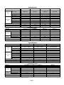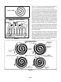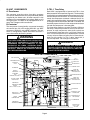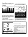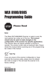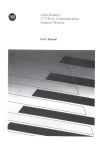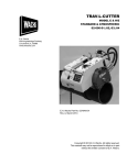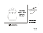
1
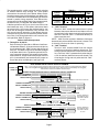
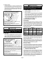
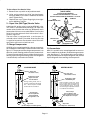
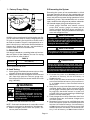
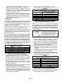
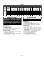
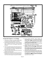
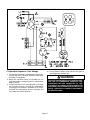
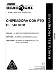
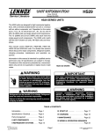
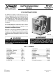
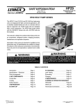
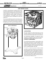
HP25 SERIES UNITS The HP25 is a high efficiency residential split–system heat pump which features a scroll compressor. It operates much like a standard heat pump, but the HP25’s scroll compressor is unique in the way that it compresses refrigerant. Several models are available in sizes ranging from 1-1/2 through 5 tons. The series uses expansion valves in the outdoor unit and in the indoor unit. ÎÎÎ This manual is divided into sections which discuss the major components, refrigerant system and charging procedures, maintenance and operation sequences. All specifications in this manual are subject to change. SCROLL COMPRESSOR DISCHARGE I–APPLICATION SUCTION All major components (indoor blower/coils) must be matched according to Lennox recommendations for the compressor to be covered under warranty. Refer to the Engineering Handbook for approved system matchups. A misapplied system will cause erratic operation and can result in early compressor failure. II–SCROLL COMPRESSOR The scroll compressor design is simple, efficient and requires few moving parts. A cutaway diagram of the scroll compressor is shown (at left). The scrolls are located in the top of the compressor can and the motor is located in the bottom of the compressor can. The oil level is immediately below the motor. The scroll is a simple compression concept centered around the unique spiral shape of the scroll and its inherent properties. Figure 1 shows the basic scroll form. Two identical scrolls are mated together forming concentric spiral shapes (figure 2). One scroll remains stationary, while the other is allowed to orbit (figure 3). Note that the orbiting scroll does not rotate or turn but merely orbits the stationary scroll. 1993 Lennox Industries Inc. SPECIFICATIONS Model No. Outdoor Coil Face area (sq.ft.) inner / outer Tube diameter (in.) No. of Rows Fins per inch Diameter (in.) No. of Blades Motor hp Condenser Fan Cfm RPM Watts HCFC–22 (charge furnished) Liquid line connection Vapor line connection HP25–211 HP25–261 HP25–311 HP25–411 10.40/11.83 8.57/11.83 15.34/15.94 15.34/15.94 3/8 1.9 20 20 4 1/10 1865 825 150 7lbs. 0oz. 3/8 5/8 3/8 1.75 18 20 4 1/10 1865 825 150 8lbs. 2oz. 3/8 5/8 3/8 2.0 18 24 3 1/6 3350 820 210 10lbs. 4oz. 3/8 3/4 3/8 2.0 18 24 3 1/6 3350 820 210 10lbs. 14oz. 3/8 3/4 ELECTRICAL DATA Model No. Line voltage data – 60hz./1 phase Compressor Rated load amps Power factor Locked rotor amps Condenser Fan Motor Full load amps Locked rotor amps Max fuse or c.b. size (amps) *Minimum circuit ampacity HP25–211 HP25–261 HP25–311 HP25–411 208/230V 9.7 208/230V 11.6 208/230V 13.5 208/230V 18.0 .96 50.0 .96 62.5 .96 76.0 .96 90.5 1.1 2.0 1.1 2.0 1.1 2.0 1.1 2.0 20 13.3 25 15.6 30 18.0 40 23.6 *Refer to National Electrical Code Manual to determine wire, fuse and disconnect size requirements. NOTE – Extremes of operating range are plus 10% and minus 5% of line voltage SPECIFICATIONS Model No. Outdoor Coil Face area (sq.ft.) inner / mid / outer Tube diameter (in.) No. of Rows Fins per inch Diameter (in.) No. of Blades Motor hp Condenser Fan Cfm RPM Watts HCFC–22 (charge furnished) Liquid line connection Vapor line connection HP25–461 HP25–511 HP25–651 17.53/ - - - /18.22 23.01/ - - - /23.92 16.83/23.01/23.92 3/8 2.0 18 24 3 1/6 3400 820 200 12lbs. 8oz. 3/8 7/8 3/8 2.0 20 24 4 1/4 3900 845 280 18lbs. 8oz. 3/8 7/8 3/8 2.76 20 24 3 1/3 4600 1090 390 23lbs. 14oz. 3/8 1-1/8 HP25–461 HP25–511 HP25–651 208/230V 20 208/230V 23.7 208/230V 28.8 .97 107 .94 129 0.94 169 1.1 2.0 1.6 2.9 2.3 4.3 40 26.1 50 31.2 60 38.4 ELECTRICAL DATA Model No. Line voltage data – 60hz./1 phase Compressor Rated load amps Power factor Locked rotor amps Condenser Fan Motor Full load amps Locked rotor amps Max fuse or c.b. size (amps) *Minimum circuit ampacity *Refer to National Electrical Code Manual to determine wire, fuse and disconnect size requirements. NOTE – Extremes of operating range are plus 10% and minus 5% of line voltage NOTE – The head of a scroll compressor may be hot since it is in constant contact with discharge gas. SCROLL FORM FIGURE 1 CROSS-SECTION OF SCROLLS DISCHARGE STATIONARY SCROLL DISCHARGE PRESSURE SUCTION TIPS SEALED BY DISCHARGE PRESSURE ORBITING SCROLL FIGURE 2 The counterclockwise orbiting scroll draws gas into the outer crescent shaped gas pocket created by the two scrolls (figure 3 – 1). The centrifugal action of the orbiting scroll seals off the flanks of the scrolls (figure 3 – 2). As the orbiting motion continues, the gas is forced toward the center of the scroll and the gas pocket becomes compressed (figure 3 – 3). When the compressed gas reaches the center, it is discharged vertically into a chamber and discharge port in the top of the compressor (figure 2). The discharge pressure forcing down on the top scroll helps seal off the upper and lower edges (tips) of the scrolls (figure 2). During a single orbit, several pockets of gas are compressed simultaneously providing smooth continuous compression. The scroll compressor is tolerant to the effects of liquid return. If liquid enters the scrolls, the orbiting scroll is allowed to separate from the stationary scroll. The liquid is worked toward the center of the scroll and is discharged. If the compressor is replaced, conventional Lennox cleanup practices must be used. HOW A SCROLL WORKS SUCTION MOVEMENT OF ORBIT INTERMEDIATE PRESSURE GAS SUCTION CRESCENT SHAPED GAS POCKET ORBITING SCROLL SUCTION POCKET 1 2 STATIONARY SCROLL SUCTION 3 MOVEMENT OF ORBIT SUCTION HIGH PRESSURE GAS 4 FIGURE 3 FLANKS SEALED BY CENTRIFUGAL FORCE DISCHARGE POCKET III–UNIT COMPONENTS A–Transformer C–TD1–1 Time Delay The contactor, reversing valve, time delay, temperature sensor and defrost timer are all powered by 24VAC supplied by the indoor unit. All other controls in the outdoor unit are powered by line voltage. Refer to unit wiring diagram. The HP25 is not equipped with an internal line voltage to 24V transformer. B–Contactor The compressor is energized by a contactor located in the control box. All units except HP25-651 use SPST contactors. HP25-651 uses a DPST contactor. The contactor is energized by indoor thermostat terminal Y when thermostat demand is present. WARNING Each HP25 is equipped with a Lennox built TD1–1 time delay located in the control box (figure 4). The time delay is electrically connected between thermostat terminal Y1 and the compressor contactor. On initial thermostat demand, the compressor contactor is delayed for 8.5 seconds. At the end of the delay, the compressor is allowed to energize. When thermostat demand is satisfied, the time delay opens the circuit to the compressor contactor coil and the compressor is de–energized. The time delay performs no other functions. Without the delay it would be possible to short cycle the compressor. A scroll compressor, when short cycled, can run backward if head pressure is still high. It does not harm a scroll compressor to run backward, but it could cause a nuisance tripout of safety limits (internal overload). For this reason, if a TD1–1 delay should fail, it must be replaced. Do not bypass the control. HP25 UNITS USING SINGLE-POLE CONTACTORS: ONE LEG OF COMPRESSOR, CAPACITOR AND CONDENSER FAN ARE CONNECTED TO LINE VOLTAGE AT ALL TIMES. POTENTIAL EXISTS FOR ELECTRICAL SHOCK RESULTING IN INJURY OR DEATH. REMOVE ALL POWER AT DISCONNECT BEFORE SERVICING. DANGER DO NOT ATTEMPT TO REPAIR THIS CONTROL. UNSAFE OPERATION WILL RESULT. IF THE CONTROL IS FOUND TO BE INOPERATIVE, SIMPLY REPLACE THE ENTIRE CONTROL. HP25 UNIT COMPONENTS DUAL CAPACITOR DEFROST TIMER TD1–1 TIME DELAY THERMOMETER WELL CONTACTOR EXPANSION VALVE DEFROST RELAY TERMINAL STRIP DISTRIBUTOR LIQUID LINE SERVICE VALVE AND GAUGE PORT DEFROST THERMOSTAT FILTER/DRIER WITH INTERNAL CHECK VALVE HIGH PRESSURE SWITCH VAPOR LINE SERVICE VALVE AND GAUGE PORT FACTORY CHARGE PROCESS PORT COMPRESSOR TEMPERATURE SENSOR HP25-211 THRU -461 ONLY SUCTION GAUGE PORT MUFFLER EXPANSION VALVE SENSING BULB SERVICE LIGHT THERMOSTAT REVERSING VALVE AND SOLENOID CHARGE COMPENSATOR COMPRESSOR COMPRESSOR TERMINAL BOX ACCUMULATOR HP25-511 AND –651 ONLY FIGURE 4 D–Terminal Strip All HP25s are equipped with a low voltage terminal strip located in the unit control box for making thermostat wiring connections (refer to figure 4). the switch opens, the circuit to the compressor contactor and the time delay is de–energized and the unit shuts off. The switch automatically resets when the compressor temperature drops below 130F + 14F. COMPRESSOR TERMINAL BOX E–Compressor Table 1 shows the specifications of compressors used in HP25 series units. DISCHARGE TEMPERATURE SENSOR WIRES TO CONTROL BOX TABLE 1 Unit HP25–211 HP25–261 HP25–311 HP25–411 HP25–461 HP25–511 HP25–651 Phase LRA RLA 1 1 1 1 1 1 1 50.0 62.5 76.0 90.5 107 129 169 9.7 11.6 13.5 18.0 20.0 26.4 32.1 COMPRESSOR TERMINALS Oil fl.oz. 24* 28* 28* 34* 38* 52* 54* C S (TO COMP. TERM. BOX IN -211 THROUGH -461 UNITS) R WARNING COMPRESSOR MUST BE GROUNDED. DO NOT OPERATE WITHOUT PROTECTIVE COVER OVER TERMINALS. DISCONNECT ALL POWER BEFORE REMOVING PROTECTIVE COVER. DISCHARGE CAPACITORS BEFORE SERVICING UNIT. COMPRESSOR WIRING DIAGRAM IS FURNISHED INSIDE COMPRESSOR TERMINAL BOX COVER. FAILURE TO FOLLOW THESE PRECAUTIONS COULD CAUSE ELECTRICAL SHOCK RESULTING IN INJURY OR DEATH. *Shipped with conventional white oil (Sontex 200LT). 3GS oil may be used if additional oil is required. F–High Pressure Switch A manual-reset single-pole single-throw high pressure switch located in the discharge line of the compressor shuts off the compressor when discharge pressure rises above the factory setting. The switch is normally closed and is permanently adjusted to trip (open) at 410 + 10 psi. See figure 4 for reset switch location. G–Temperature Sensor Scroll compressors in HP25-211 through -461 units are equipped with a temperature sensor located on the outside top of the compressor. The sensor is a SPST thermostat which opens when the discharge temperature exceeds 280F + 8F on a temperature rise. When FIGURE 5 The sensor can be accessed by prying off the snap plug on top of the compressor (see figure 6). Make sure to securely reseal the sensor after replacement. The sensor pigtails are located inside the unit control box. Figure 5 shows the arrangement of compressor line voltage terminals and discharge sensor pigtails. SCROLL HIGH TEMPERATURE LIMIT CHANGEOUT PLASTIC CAP SEALANT (BLUE) PRONG THERMAL GREASE (WHITE) GROMMET LIMIT (THERMOSTAT) COMPRESSOR Instructions 1- With power off, disconnect wiring to limit. 2- Dislodge limit/cap assembly from compressor. Plastic cap and silicone seal will break away. Discard all pieces. 3- Remove thermostat and grommet from compressor. Thoroughly clean all blue adhesive and white silicone thermal grease from compressor and the inside the thermostat tube. Thermostat tube should be clean and free of debris. 4- Using Lennox kit 93G8601, dip end of thermostat into plastic bottle labeled “Silicone Thermal Grease G.E. #G641” and coat end of thermostat. Carefully insert thermostat/grommet assembly into thermostat tube of compressor. Avoid contact with top of compressor. 5- Clean excess thermal grease from under cap lip and top lip of compressor opening. 6- Install protector assembly as shown, feeding wire leads through channel provided in cap. 7- Apply a bead of sealant around lip of cap at area shown in illustration and into the thermostat tube area. 8- Install assembly as shown. Align wires to channel in compressor shell. Sufficient force is required to snap plastic cap into tube to engage all three prongs. 9- Re-connect wiring. 10-After completing thermostat replacement, discard remaining parts. FIGURE 6 H–Service Light Thermostat TABLE 2 All units are equipped with a service light thermostat located on the compressor discharge line. The switch is electrically connected to the service light in the indoor thermostat. The switch is closed on compressor startup and the thermostat service light is momentarily lighted. When compressor discharge line temperature reaches 130+5F, the thermostat opens and the service light goes off. If discharge line temperature drops below 110+5F during unit operation, (indicating a problem in the system), the thermostat closes and the service light is powered to indicate service is needed. I–Outdoor Fan Motor The specifications table on page 2 of this manual shows the specifications of outdoor fans used in HP25s. In all units, the outdoor fan is controlled by the compressor contactor and is de–energized when the defrost relay is energized. J–Ambient Compensating Thermistor All HP25s have an ambient compensating thermistor mounted on the outdoor fan wiring harness. The thermistor is an NTC thermistor (negative temperature coefficient – increase in temperature equals decrease in resistance) (see figure 7). The device is connected in series with the heat anticipation resistor inside the indoor thermostat.This feature helps to prevent abnormal droop caused by the anticipation resistors. As outdoor temperature increases, the resistance across the thermistor drops. As the resistance across the thermistor drops, the current through the heat anticipation resistor increases. Therefore, heat anticipation increases as outdoor temperature decreases. Resistance at 77F = 260 ohms + 5%; at 100F = 150 ohms; at 32F = 861 ohms. OUTDOOR FAN, BRACKET AND AMBIENT COMPENSATING THERMISTOR HP25 DUAL CAPACITOR RATING Terminal Units MFD FAN 5 HP25–211 HERM 25 FAN 5 HP25–261 HERM 30 FAN 5 HP25–311 HERM 35 FAN 5 HP25–411, -461 HERM 35 FAN 10 HP25–511 HERM 40 FAN 10 HP25–651 HERM 55 VAC 370 440 L–Defrost Thermostat A defrost thermostat is mounted on the liquid line between the filter/drier and the distributor. The thermostat opens at 70+5F and closes at 35+5F. For defrost to begin, the defrost thermostat must be closed when the defrost timer calls for defrost. M–Defrost Relay The defrost relay controls defrost. The relay is a 3PDT relay powered 24 VAC from the thermostat and is enabled during both cooling and heating modes (except emergency heat). It is only powered when the defrost control is calling for defrost. When energized, the reversing valve and indoor auxiliary heat are energized. Simultaneously, the outdoor fan is de-energized. The defrost relay latches in for the duration of the defrost period. Refer to unit wiring diagram and operation sequence in the back of this manual. N–Reversing Valve and Solenoid A refrigerant reversing valve with electromechanical solenoid is used to reverse refrigerant flow during unit operation. The reversing valve is energized during cooling demand and during defrost. Refer to figures 12 and 13 for more information. O–Defrost Timer The CMC1 defrost control (figure 8) is a solid state control manufactured by Hamilton Standard. The control provides automatic switching from normal heating operation to defrost mode and back. The control provides 14 minute defrost periods at 30, 60 or 90 minute field changeable intervals. The control monitors thermostat demand and holds the timer in place between thermostat demand. A set of diagnostic pins are also provided for troubleshooting the unit. SOLID STATE DEFROST CONTROL CMC1 FIGURE 7 Timing Pins K–Dual Capacitor Troubleshooting Pins 30 The compressor and fan in all units use permanent split capacitor motors. A single ‘dual’ capacitor is used for both the fan motor and the compressor (see unit wiring diagram). The fan side of the capacitor and the compressor side of the capacitor have different mfd ratings. The capacitor is located inside the unit control box (see figure 4). Table 2 shows the ratings of the dual capacitor. 60 90 Timing Jumper FIGURE 8 Control Terminals The control contains a solid state timer which switches an external defrost relay through 1/4” male spades mounted on the control’s circuit board. When the defrost thermostat closes (call for defrost), the defrost timer initiates a 30, 60 or 90 minute (depending on how the control is preset) timing sequence. If the defrost thermostat remains closed when the timing sequence ends, the defrost relay is energized and defrost begins. A defrost period can last up to 14 minutes and can be terminated two ways. If the defrost thermostat does not open within 14 minutes after defrost begins, the timer will de–energize the defrost relay and the unit will resume normal operation. If the defrost thermostat opens during the 14 minute defrost period, the defrost relay is de–energized and the unit resumes normal operation. Refer to figure 9. Defrost Control Components 1– Timing Pins 30, 60, 90 TABLE 3 CMC1 DEFROST CONTROL TIMINGS NORMAL OPERATION “TST” PINS JUMPER TOGETHER CLOSED, ON OPEN, OFF 30 + 3 MIN. 60 + 6 MIN. 90 + 9 MIN. 14 + 1.4 MIN. 7 + 0.7 SEC. 14 + 1.4 SEC. 21 + 2.1 SEC. 3.3 + 0.3 SEC. 2– “HLD” Terminal Terminal “HLD” holds the internal timer in place between thermostat demands and allows the unit to continue timing upon resumption of thermostat demand. Terminal “HLD” is connected directly to thermostat demand. NOTE – Hold function operates between thermostat demands only when defrost thermostat is closed. This is the only time that the timer is operating. 3– “24V” Terminal Terminal “24V” receives 24VAC from the control transformer through the defrost thermostat. This terminal powers the control’s internal timer and relays. Terminal “24V” is powered only when there is a call for defrost (defrost thermostat closed). The timer begins timing at 0 only after terminal “24V” receives power. Each of these pins provides a different timed interval between defrosts. A jumper connects the pins to circuit board pin W1. Table 3 shows the timings of each pin. The defrost interval can be field changed to 30, 60 or 90 minutes. The defrost period (14 minutes) cannot be changed. To change the interval between defrosts, simply remove the jumper from the pin it is connected to and reconnect the jumper to one of the other available pins (see figure 10). ÉÉ ÉÉ ÉÉ INTERVAL BETWEEN DEFROSTS WITH JUMPER CONNECTED TO: DEFROST TIME 30 60 90 HP25 SERIES UNITS TYPICAL DEFROST TIMINGS Note – Control begins timing at 0 when defrost thermostat closes. Defrost is terminated when defrost relay is de–energized. Anytime defrost thermostat opens, defrost relay is immediately de–energized, defrost timer resets and “HOLD” function stops. ÉÉÉÉÉÉÉÉÉÉÉÉÉÉÉÉÉ ÉÉÉÉÉÉÉÉÉ ÉÉÉÉÉÉÉÉÉÉÉÉÉÉÉÉÉ ÉÉ ÉÉÉÉÉÉÉÉÉ ÉÉÉÉÉÉÉÉÉÉÉÉÉÉÉÉÉÉÉÉÉÉÉ ÉÉÉÉÉÉÉÉÉÉÉÉÉÉÉÉÉÉÉÉÉ ÉÉÉÉÉÉÉÉÉÉÉÉÉÉÉÉÉÉÉÉÉÉÉ ÉÉÉ ÉÉÉ ÉÉÉÉÉÉÉÉÉÉÉÉÉÉÉÉÉÉÉÉÉ ÉÉÉÉÉÉÉÉÉ ÉÉÉÉÉÉÉÉÉÉÉÉÉÉÉÉÉ ÉÉÉÉÉÉÉ ÉÉÉÉ ÉÉÉÉÉÉÉÉÉÉÉÉÉÉÉÉÉ ÉÉÉÉ ÉÉÉÉÉÉÉÉÉ ÉÉÉÉÉÉÉ ÉÉÉÉÉÉÉÉÉÉÉÉ ÉÉÉÉÉÉÉÉÉ ÉÉÉÉÉÉÉ ÉÉ ÉÉ ÉÉÉÉÉÉÉÉÉÉÉÉ ÉÉ ÉÉ NORMAL HEATING OPERATION: DEFROST TERMINATED BY DEFROST THERMOSTAT THERMOSTAT DEMAND DEFROST THERMOSTAT DEFROST RELAY 30/60/90 MINUTES DEFROST THERMOSTATOPEN WITHIN 14 MINUTES NORMAL HEATING OPERATION: DEFROST TERMINATED BY TIME THERMOSTAT DEMAND DEFROST THERMOSTAT DEFROST RELAY 30/60/90 MINUTES 14 MIN. 30/60/90 MINUTES NORMAL HEATING OPERATION INTERRUPTED BY THERMOSTAT DEMAND: “HOLD” FUNCTION DEFROST THERMOSTAT MUST REMAIN CLOSED FOR TIMER TO REMAIN IN “HOLD” THERMOSTAT DEMAND DEFROST THERMOSTAT DEFROST RELAY “HOLD” TIME 30/60/90 MINUTES PLUS “HOLD” TIME DEFROST PERIOD INTERRUPTED BY THERMOSTAT DEMAND: “HOLD” FUNCTION THERMOSTAT DEMAND DEFROST THERMOSTAT DEFROST RELAY “HOLD” TIME 30/60/90 MINUTES 14 MIN. PLUS “HOLD” TIME FIGURE 9 DEFROST THERMOSTAT MUST REMAIN CLOSED FOR TIMER TO REMAIN IN “HOLD” 4– Timing Jumper The timing jumper is a factory installed jumper on the circuit board used to connect pin W1 to one of the three timing pins. The jumper may be connected to any one of the timing pins but must never be connected to either of the “TST” pins. See Caution below. IMPORTANT Control will begin test mode only if normal load is applied to control terminals. Do not attempt to operate or test control out of unit. 6– “COM” Terminal Terminal “COM” provides 24VAC Common. 7– “OUT” Terminal Terminal “OUT” controls defrost when connected to one side of the defrost relay coil. An internal relay connected to terminal “OUT” closes to allow external defrost relay to energize and initiate defrost. At the end of the defrost period, the internal relay connected to terminal “OUT” opens to deenergize the external defrost relay. DEFROST CONTROL TIMING CHANGES WARNING – AVOID CONTACT WITH OTHER CONTROL TERMINALS OR CONTROL COMPONENTS. WARNING – DO NOT CONNECT TIMING JUMPER TO EITHER “TST” PIN. IV–REFRIGERANT SYSTEM A–Plumbing TO CHANGE CONTROL TIMINGS: 1– Turn off all power to the unit to avoid circuit board damage. 2– Grasp wire connector firmly with fingers. 3– Gently pull connector from pin. 4– Select new timing pin. DO NOT SELECT A “TST” PIN. 5– Gently push connector onto desired pin (see Table 3 for timings). 6– Turn on power to unit. FIGURE 10 CAUTION Field refrigerant piping consists of liquid and vapor lines from the outdoor unit (sweat connections). Use Lennox L10 series line sets as shown in table 4 or field fabricated refrigerant lines. Refer to the piping section of the Lennox Service Unit Information Manual (SUI–803–L9) for proper size, type and application of field–fabricated lines. TABLE 4 Model No. Do not connect timing jumper to either TST" pin. TST" pins are used only during a test and must not connect with any of the timing pins. Control damage will result. 5– “TST” Pins Each board is equipped with a set of test pins for use in troubleshooting the unit. When jumpered together, these pins reduce the control timing to about 1/256 original time (see table 3 and figure 11). DEFROST CONTROL TEST MODE WARNING – AVOID CONTACT WITH OTHER CONTROL TERMINALS OR CONTROL COMPONENTS. TO PLACE CONTROL IN TEST MODE: 1– Turn off all power to avoid damaging the circuit board. 2– Make sure all control terminals are connected as shown on unit wiring diagram before attempting to place control in test mode. See NOTE below. NOTE – Control will not go into test mode when disconnected from unit. Unit load must be applied to control terminals before the control will go into test mode. However, if outdoor ambient is 40F or warmer, the defrost thermostat may not close and may not allow test mode to initiate. If this happens, it may be necessary to jumper 24V to the 24V terminal in order to initiate defrost. 3– Connect jumper to “TST” pins as shown. 4– Turn indoor thermostat to heat mode and adjust to highest temperature setting. 5– Turn on power to unit. 6– See Table 3 for control timings in “TST” mode. 7– Be sure to turn off power and remove jumper when test is complete. Turn on power and re–adjust thermostat. FIGURE 11 HP25–211 HP25–261 HP25–311 HP25–411 HP25–461 HP25-511 HP25–651 LIQUID LINE VAPOR LINE L10 LINE SETS L10–26 20 ft. – 50 ft. 3/8 in. 5/8 in. 3/8 in. 3/4 in. L10–41 20 ft. – 50 ft. 3/8 in. 7/8 in. 3/8 in. 1-1/8 in. L10–65 20 ft. – 50 ft. Field Fabricate A check valve and expansion valve are used in parallel in the liquid line. The check valve is closed when the unit is in heating mode to force refrigerant through the expansion valve. The check valve is open when the unit is in cooling mode. Separate discharge and vapor service ports are provided at the compressor for connection of gauge manifold during charging procedure. Figures 12 and 13 show HP25 gauge manifold connections. B–Service Valves The liquid line and vapor line service valves and gauge ports are accessible from outside of the unit. Full service liquid and vapor line valves are used. See figures 14 and 15. The service ports are used for leak testing, evacuating, charging and checking charge. 1 – Liquid Line Service Valve A full-service liquid line valve made by one of several manufacturers may be used. All liquid line service valves function the same way, differences are in construction. Valves manufactured by Parker are forged assemblies. Valves manufactured by Primore are brazed together. Valves are not rebuildable. If a valve has failed it must be replaced. The liquid line service valve is illustrated in figure 14. HP25 COOLING CYCLE (SHOWING GAUGE MANIFOLD CONNECTIONS) OUTDOOR UNIT DEFROST THERMOSTAT EXPANSION VALVE OUTDOOR COIL CHARGE REVERSING COMPENSATOR VALVE NOTE – ARROWS INDICATE DIRECTION OF REFRIGERANT FLOW FILTER / DRIER WITH INTERNAL CHECK VALVE STRAINER HIGH SUCTION PRESSURE HIGH PRESSURE LIMIT S4 INDOOR UNIT INTERNAL COMPRESSOR LIMIT SUCTION SERVICE PORT MUFFLER CHECK VALVE TO HCFC-22 DRUM VAPOR LINE VALVE LIQUID LINE SERVICE PORT COMPRESSOR INDOOR COIL EXPANSION VALVE OR RFCIII THERMOMETER WELL FIGURE 12 HP25 HEATING CYCLE (SHOWING GAUGE MANIFOLD CONNECTIONS) DEFROST THERMOSTAT OUTDOOR UNIT EXPANSION VALVE OUTDOOR COIL FILTER / DRIER WITH INTERNAL CHECK VALVE STRAINER SUCTION HIGH PRESSURE CHARGE REVERSING COMPENSATOR VALVE INDOOR UNIT INTERNAL HIGH PRESSURE COMPRESSOR LIMIT LIMIT S4 SUCTION SERVICE PORT MUFFLER TO HCFC-22 DRUM LIQUID LINE SERVICE PORT NOTE – ARROWS INDICATE DIRECTION OF REFRIGERANT FLOW VAPOR LINE VALVE CHECK VALVE COMPRESSOR THERMOMETER WELL EXPANSION VALVE OR RFCIII INDOOR COIL FIGURE 13 5– Replace service port and stem cap. Tighten finger The valve is equipped with a service port. There is no tight, then tighten an additional 1/6 turn. schrader valve installed in the liquid line service port. A service port cap is supplied to seal off the port. To Close Off Service Port: The liquid line service valve is a front and back seating valve. When the valve is backseated the service port is not pressurized. The service port cap can be removed and gauge connections can be made. 1– Using service wrench, backseat valve. a – Turn stem counterclockwise. b – Tighten firmly. To Access Service Port: 1– Remove the stem cap with an adjustable wrench. 2– Using service wrench, backseat valve. a – Turn stem counterclockwise until backseated. b – Tighten firmly. 3– Replace stem cap, finger tighten then tighten an additional 1/6 turn. To Close Liquid Line Service Valve: 1– Remove the stem cap. Use a service wrench (part #18P66, 54B64 or 12P95) to make sure the service valve is backseated. 2– Remove service port cap and connect high pressure gauge to service port. 3– Using service wrench, open valve stem (one turn clockwise) from backseated position. 4– When finished using port, backseat stem with service wrench. Tighten firmly. To Open Liquid Line Service Valve: 1– Remove the stem cap with an adjustable wrench. 2– Turn the stem in clockwise with a service wrench to front seat the valve. Tighten firmly. The valve is equipped with a service port. A schrader valve is factory installed. A service port cap is supplied to protect the schrader valve from contamination and assure a leak free seal. VAPOR LINE SERVICE VALVE (VALVE OPEN) LIQUID LINE SERVICE VALVE TO CONDENSER COIL SNAP RING KNIFE EDGE SEAL INSERT HEX WRENCH HERE (PART #49A71 AND SERVICE WRENCH) INLET (FROM INDOOR COIL) TO LINE SET NO SCHRADER STEM CAP SCHRADER VALVE SERVICE PORT CAP SERVICE PORT CAP OUTLET (TO COMPRESSOR) SERVICE PORT SERVICE PORT OPEN TO LINE SET WHEN FRONT SEATED AND CLOSED (OFF) WHEN BACK SEATED VAPOR LINE SERVICE VALVE (VALVE CLOSED) KNIFE EDGE SEAL KNIFE EDGE SEAL VALVE STEM USE SERVICE WRENCH (PART #18P66, 54B64 or 12P95) SNAP RING STEM CAP INLET (FROM INDOOR COIL) INSERT HEX WRENCH HERE (PART #49A71 AND SERVICE WRENCH) STEM CAP SERVICE PORT SERVICE PORT CAP IMPORTANT A schrader valve is not provided on the liquid line service port. Valve must be backseated to turn off pressure to service port. SCHRADER VALVE OPEN TO LINE SET WHEN VALVE IS CLOSED (FRONT SEATED) FIGURE 14 CAUTION The service port cap is used to seal the liquid line service valve. Access to service port requires backseating the service valve to isolate the service port from the system. Failure to do so will cause refrigerant leakage. 3– Replace stem cap, finger tighten then tighten an additional 1/6 turn. 2 – Vapor Line Service Valve A full service non-backseating vapor line service valve is used on all HP25 series units. Different manufacturers of valves may be used. All vapor line service valves function the same way, differences are in construction. Valves manufactured by Parker are forged assemblies. Primore and Aeroquip valves are brazed together. Valves are not rebuildable. If a valve has failed it must be replaced. The vapor line service valve is illustrated in figure 15. (VALVE FRONT SEATED) OUTLET (TO COMPRESSOR) FIGURE 15 To Access Schrader Port: 1– Remove service port cap with an adjustable wrench. 2– Connect gauge to the service port. 3– When testing is completed, replace service port cap. Tighten finger tight, then tighten an additional 1/6 turn. To Open Vapor Line Service Valve: 1– Remove stem cap with an adjustable wrench. 2– Using service wrench and 5/16” hex head extension (part #49A71) back the stem out counterclockwise until the valve stem just touches the retaining ring. DANGER Do not attempt to backseat this valve. Attempts to backseat this valve will cause snap ring to explode from valve body under pressure of refrigerant. Personal injury and unit damage will result. 3– Replace stem cap tighten firmly. Tighten finger tight, then tighten an additional 1/6 turn. To Close Vapor Line Service Valve: VAPOR LINE (BALL TYPE) SERVICE VALVE (VALVE OPEN) 1– Remove stem cap with an adjustable wrench. 2– Using service wrench and 5/16” hex head extension (part #49A71) turn stem in clockwise to seat the valve. Tighten firmly. 3– Replace stem cap. Tighten finger tight, then tighten an additional 1/6 turn. USE ADJUSTABLE WRENCH ROTATE STEM CLOCKWISE 90 TO CLOSE ROTATE STEM COUNTER-CLOCKWISE 90 TO CLOSE STEM CAP INLET (FROM INDOOR COIL) 3 – Vapor Line (Ball Type) Service Valve STEM A ball-type full service valve is used on HP25-651 units. This valve is manufactured by Aeroquip. All vapor line service valves function the same way, differences are in construction. Valves are not rebuildable. If a valve has failed it must be replaced. A ball valve valve is illustrated in figure 16. The ball valve is equipped with a service port. A schrader valve is factory installed. A service port cap is supplied to protect the schrader valve from contamination and assure a leak free seal. BALL (SHOWN OPEN) OUTLET (TO COMPRESSOR) SERVICE PORT CAP SERVICE PORT SCHRADER VALVE C–Charge Compensator FIGURE 16 All HP25 units are equipped with a charge compensator in addition to the factory installed accumulator. See figure 17. The purpose of the charge compensator is to optimize system heating performance by automatically removing and storing excess refrigerant during the heating cycle. During the cooling cycle, the refrigerant is automatically returned to circulation. D–Accumulator HP25 -511 and -651 units are equipped with an accumulator in addition to the factory installed charge compensator. See figure 17. The purpose of the accumulator is to trap and evaporate all liquid refrigerant and prevent liquid refrigerant from entering the compressor. CHARGE COMPENSATOR OPERATION COOLING MODE HEATING MODE Vapor Line (To Outdoor Coil) Vapor Line (From Outdoor Coil) Compensator Tank Liquid Is Forced Into Circulation Compensator Tank Fills With Liquid During cooling mode, the vapor line is hotter than the liquid line. Stored liquid is heated and forced into circulation. During heating mode, the vapor line is cooler than the liquid line. Excess vapor from the indoor coil (non-condensed vapor) is forced into the charge compensator where it condenses and collects. Excess Vapor In From Outdoor Coil To Be Condensed and Stored In Compensator as Liquid Stored Liquid Out To Liquid Line To Be Circulated Through Indoor coil Vapor Line (To Compressor Suction Port) Vapor Line (From Compressor Discharge Port) FIGURE 17 1 – Factory Charge Fitting B–Evacuating the System FACTORY PROCESS PORT LIQUID LINE ASSEMBLY PROCESS PORT CAP / SEAL FIGURE 18 Evacuating the system of non–condensables is critical for proper operation of the unit. Non–condensables are defined as any gas that will not condense under temperatures and pressures present during operation of an air conditioning system. Non–condensable such as water vapor, combines with refrigerant to produce substances that corrode copper piping and compressor parts. 1– Attach gauge manifold and connect vacuum pump (with vacuum gauge) to center port of gauge manifold. With both gauge manifold service valves open, start pump and evacuate evaporator and refrigerant lines. IMPORTANT All HP25 units are equipped a liquid charging port (figure 18) used exclusively for factory charging the unit. This port is located in the liquid line as shown and is not field serviceable. The port is equipped with an internal valve (the cap / seal can be removed without refrigerant loss). However, the cap / seal should be secured in order to ensure a leak-free seal. A temperature vacuum gauge, mercury vacuum (U–tube), or thermocouple gauge should be used. The usual Bourdon tube gauges are not accurate enough in the vacuum range. IMPORTANT V–CHARGING The compressor should never be used to evacuate a refrigeration or air conditioning system. Unit charge is based on a matching indoor coil and outdoor coil with a 25 foot (7620mm) line set. For varying lengths of line set, refer to table 5. TABLE 5 Liquid Line Set Diameter Ounce per 5 foot (ml per mm) adjust from 20 ft. (6096mm)* All Sizes 3 ounce per 5 feet (90 ml per 1524 mm) CAUTION Danger of Equipment Damage. Avoid deep vacuum operation. Do not use compressors to evacuate a system. Extremely low vacuums can cause internal arcing and compressor failure. Damage caused by deep vacuum operation will void warranty. *If line set is greater than 20 ft. (6.10m) add this amount. If line set is less than 20 ft. (6.10m) subtract this amount A–Leak Testing 1– Attach gauge manifold and connect a drum of dry nitrogen to center port of gauge manifold. 2– Add a small amount of refrigerant to the lines and coil. Open high pressure valve on gauge manifold and pressurize line set and indoor coil to 150 psig (1034 kPa). WARNING Danger of Explosion. Can cause injury, death and equipment damage. When using dry nitrogen, use a pressure–reducing regulator, set at 150 psig (1034 kPa) or less to prevent excessive pressure. 3– Check lines and connections for leaks. NOTE – If electronic leak detector is used, add a trace of refrigerant to nitrogen for detection by leak detector. 4– Release nitrogen pressure from the system, correct any leaks and recheck. 2– Evacuate the system to an absolute pressure of .92 inches of mercury, 23 mm of mercury, or 23,000 microns. 3– After system has been evacuated to an absolute pressure of.92 iches of mercury, 23 mm of mercury, or 23,000 microns, close manifold valve to center port. 4– Stop vacuum pump and disconnect from gauge manifold. Attach a drum of dry nitrogen to center port of gauge manifold, open drum valve slightly to purge line, then break vacuum in system to 3 psig (20.7 kPa) pressure by opening manifold high pressure valve to center port. 5– Close nitrogen drum valve, disconnect drum from manifold center port and release nitrogen pressure from system. 6– Reconnect vacuum pump to manifold center port hose. Evacuate the system to an absolute pressure less than .197 inches of mercury, 5 mm of mercury, or 5000 microns, then turn off vacuum pump. If the absolute pressure rises above .197 inches of mercury, 5 mm of mercury, or 5000 microns within a Add refrigerant to make the liquid line cooler. Recover refrigerant to make the liquid line warmer. TABLE 6 20–minute period after stopping vacuum pump, repeat step 6. If not, evacuation is complete. This evacuation procedure is adequate for a new installation with clean and dry lines. If excessive moisture is present, the evacuation process may be required more than once. 7– After evacuation has been completed, close gauge manifold service valves. Disconnect vacuum pump from manifold center port and connect refrigerant drum. Pressurize system slightly with refrigerant to break vacuum. APPROACH METHOD – EXPANSION VALVE SYSTEMS AMBIENT TEMPERATURE OF 60 F (16 C) OR ABOVE Liquid Line °F Warmer Than Outside Model (Ambient) Temperature HP25–211 HP25–261 HP25–311 HP25–411 HP25–461 HP25–511 HP25–651 C–Charging Charging must be done in the cooling mode. If system is completely void of refrigerant, the recommended and most accurate method of charging is to weigh the refrigerant into the unit according to the total amount shown on the unit nameplate. If weighing facilities are not available or if unit is just low on charge, the following procedure applies. Separate discharge and vapor line service ports are provided outside the unit for connection of gauge manifold during charging procedure as well as a suction line service port. The following procedures are intended as a general guide for use with expansion valve systems only. For best results, indoor temperature should be between 70 °F and 80 °F. If outdoor temperature is 60 °F (16 °C) or above the approach method of charging is used. If outdoor temperature is less than 60 °F (16 °C) the subcooling method of charging is used. Slight variations in charging temperature and pressure should be expected. Large variations may indicate a need for further servicing. IMPORTANT The following procedures require accurate readings of ambient (outdoor) temperature, liquid temperature and liquid pressure for proper charging. Use a thermometer with accuracy of +2 °F and a pressure gauge with accuracy of +5 PSIG. APPROACH METHOD (TXV SYSTEMS) (Ambient Temperature of 60F [16C] or Above) 1– Connect gauge manifold. Connect an upright HCFC-22 drum to center port of gauge manifold. 2– Record outdoor air (ambient) temperature. 3– Operate indoor and outdoor units in cooling mode. Allow outdoor unit to run until system pressures stabilize. 4– Make sure thermometer well is filled with mineral oil before checking liquid line temperature. 5– Place thermometer in well and read liquid line temperature. Liquid line temperature should be a few degrees warmer than the outdoor air temperature. Table 6 shows how many degrees warmer the liquid line temperature should be. 8 8 8 9 9 5 5 SUBCOOLING METHOD (TXV SYSTEMS) (Ambient Temperature Below 60F [16C] ) NOTE – It may be necessary to restrict air flow in order to reach liquid pressures in the 200-250 psig range which are required for checking charge. Block equal sections of air intake panels as shown in figure 19, moving obstructions sideways until liquid pressures in the 200-250 psig range are reached. BLOCKING OUTDOOR COIL Block outdoor coil one side at a time with cardboard or plastic sheets until proper testing pressures are reached. CARDBOARD OR PLASTIC SHEET FIGURE 19 1– Connect gauge manifold. Connect an upright HCFC-22 drum to center port of gauge manifold. 2– Operate indoor and outdoor units in cooling mode. Allow units to run until system pressures stabilize. 3– Make sure thermometer well is filled with mineral oil before checking liquid line temperature. 4– Read liquid line pressure and convert to condensing temperature using temperature/ pressure conversion chart. Condensing temperature (from gauges) should be a few degrees warmer than the liquid line. 5– Place thermometer in well and read liquid line temperature. Table 7 shows how much warmer the condensing temperature should be. TABLE 7 SUBCOOLING METHOD – EXPANSION VALVE SYSTEMS AMBIENT TEMPERATURE BELOW 60 F (16 C) Model Condensing Temp°F Warmer Than Liquid Line HP25–211 HP25–261 HP25–311 HP25–411 HP25–461 HP25–511 HP25–651 8+2 3+2 3+2 3+2 8+2 10 + 2 12 + 2 Add refrigerant to make the liquid line cooler. Recover refrigerant to make the liquid line warmer. 6– When unit is properly charged liquid line pressures should approximate those given in table 8. TABLE 8 NORMAL OPERATING PRESSURES MODE/ TYPE OF EXPANSION C li Cooling TXV Only Heating OUTDOOR COIL AIR ENTERING TEMPERATURE 75F 85F 95F 105F 20F 30F 40F 50F HP26-211 HP26-261 HP26-311 HP26-411 HP26-461 HP26-511 HP26-651 LIQ. +10 PSIG SUC. +5 PSIG LIQ. +10 PSIG SUC. +5 PSIG LIQ. +10 PSIG SUC. +5 PSIG LIQ. +10 PSIG SUC. +5 PSIG LIQ. +10 PSIG SUC. +5 PSIG LIQ. +10 PSIG SUC. +5 PSIG LIQ. +10 PSIG SUC. +5 PSIG 164 194 223 253 173 183 195 208 79 81 83 85 31 40 49 59 180 210 241 270 175 184 194 204 76 78 80 82 32 42 51 61 175 195 225 255 175 185 198 211 76 78 80 82 31 41 50 60 180 200 230 260 176 187 200 219 73 75 77 79 29 35 46 54 170 200 235 267 177 195 210 230 74 76 78 80 29 35 46 56 168 185 225 260 182 190 200 224 72 73 74 75 26 40 45 56 174 203 233 269 205 235 243 250 74 75 76 78 26 40 51 53 IMPORTANT IMPORTANT Use table 8 as a general guide for performing maintenance checks. Table 8 is not a procedure for charging the system. Minor variations in pressures may be expected due to differences in installations. Significant deviations may mean the system is not properly charged or that a problem exists with some component in the system. Used prudently, table 8 could serve as a useful service guide. If insufficient heating or cooling occurs, the unit should be gauged and refrigerant charge checked. B–Indoor Coil 1– Clean coil if necessary. 2– Check lines and coil for evidence of oil leaks. 3– Check condensate line and clean if necessary. D–Oil Charge C–Indoor Unit Refer to table 1 on page 3. 1– Clean or change filters. 2– Adjust blower cooling speed. Static pressure drop over coil should be checked to determine correct blower CFM. Refer to Lennox Engineering Handbook. 3– Belt Drive Blowers - Check condition and tension. 4– Check all wiring for loose connections. 5– Check for correct voltage at unit. 6– Check amp–draw on blower motor. Unit nameplate_________Actual_________. VI–MAINTENANCE At the beginning of each heating or cooling season, the system should be cleaned as follows: A–Outdoor Unit 1– Clean and inspect outdoor coil. (Coil may be flushed with a water hose). 2– Visually inspect all connecting lines, joints and coils for evidence of oil leaks. VII–WIRING DIAGRAM/OPERATING SEQUENCE A–Field Wiring HP25 and BLOWER UNIT THERMOSTAT CONNECTIONS (WITH OR WITHOUT AUXILIARY HEAT) (Some connections may not apply. Refer to specific thermostat and indoor unit.) Indoor Blower Unit Thermostat T L O Y1 EMERGENCY HEAT E W2 W1 2ND STAGE AUX. HEAT REVERSING VALVE COMPRESSOR COMMON POWER R 1ST STAGE AUX. HEAT T L O Y1 C W2 W1 INDOOR BLOWER G SERVICE LIGHT C POWER R AMBIENT SENSOR E COMMON C HP25 DEFROST SENSING R W1 G FIELD WIRING THERMOSTAT COMPRESSOR CONTACTOR FACTORY WIRING VALID FOR GE/ HONEYWELL TYPE INDOOR THERMOSTAT. IF WHITE RODGERS TYPE INDOOR THERMOSTAT IS USED, DISCONNECT WIRE FROM COMMON AND RECONNECT TO Y TERMINAL. REFER TO UNIT RATING PLATE FOR MAXIMUM CIRCUIT AMPACITY AND MAXIMUM FUSE SIZE. T L O Y E X RH R W G R W1 G 208–230/60/1 L2 L1 COMMON/GROUND 3 W2 OUTDOOR UNIT LOW VOLTAGE TERMINALS O Y W R C L T USE COPPER CONDUCTOR ONLY S54 OUTDOOR THERMOSTAT (IF USED) EM HEAT RELAY 1 INDOOR UNIT JUNCTION BOX EXTRA LOW VOLTAGE FACTORY INSTALLED LINE VOLTAGE FACTORY INSTALLED EXTRA LOW VOLTAGE FIELD INSTALLED LINE VOLTAGE FIELD INSTALLED LOW VOLTAGE OPERATION SEQUENCE USED ON “651” SERIES UNITS ONLY B–Operation Sequence – Low Voltage 1– Transformer in indoor unit supplies 24VAC power to the thermostat and outdoor unit controls. 2– Cooling demand energizes thermostat terminals Y and O. Voltage from terminal Y passes through high pressure switch and energizes compressor contactor. 3– Thermostat demand (from thermostat terminal Y) is also supplied to the defrost control. Defrost control cannot operate in cooling mode because defrost thermostat cannot close. 4– Thermostat demand (from thermostat terminal O) energizes reversing valve. 5– Heating demand energizes thermostat terminal Y. Voltage from terminal Y passes through high pressure switch and energizes compressor contactor. 6– During heating operation, when outdoor coil drops below 35 + 4 F, the defrost thermostat closes. When defrost thermostat closes, defrost timer begins timing. If defrost thermostat remains closed at the end of 30, 60 or 90 minutes, defrost relay energizes and defrost begins. 7– When defrost relay energizes, reversing valve and indoor electric heat relay are energized. 8– Defrost continues until 14 + 1 minutes have elapsed or until the defrost thermostat opens. When defrost thermostat opens to terminate defrost, the defrost timer loses power and resets. Defrost timing is stopped until the next call for defrost (when defrost thermostat closes). 9– After each thermostat demand, time delay locks– out the circuit to conpressor contactor coil and defrost control for 5 + 2 minutes. At the end of the timed period, the time delay allows the compressor contactor and defrost control to be energized upon demand as in step 2. LINE VOLTAGE OPERATION SEQUENCE C–Operation Sequence – Line Voltage 1– Compressor contactor is energized by indoor thermostat demand. Contactor contacts close when contactor is energized. 2– When the contactor closes, the outdoor fan immediately begins operating and the compressor begins startup. 3– Compressor terminal C is energized by L1 through the contactor contacts. Terminal R is powered by L2 through the contactor (powered at all times). Terminal S is powered by the start capacitor and the H side of the dual capacitor. 4– During defrost, defrost relay contacts 4-5 open to de-energize the outdoor fan. WARNING HP25 UNITS USING SINGLE-POLE CONTACTORS: ONE LEG OF COMPRESSOR, CAPACITOR AND CONDENSER FAN ARE CONNECTED TO LINE VOLTAGE AT ALL TIMES. POTENTIAL EXISTS FOR ELECTRICAL SHOCK RESULTING IN INJURY OR DEATH. REMOVE ALL POWER AT DISCONNECT BEFORE SERVICING. D–Complete Diagram USED ON “651” SERIES UNITS ONLY