1
Visual Control
DT
USER MANUAL
ROBE Lighting s.r.o.
Czech republic
www.robe.cz
Table of contents
I Preface
1
II First steps
3
1. 3D stage
2. Your first stage
III User mode
2
3
7
1. Rendering options
2. Resolution
3. Cameras
4. DMX levels
5. Universes patch
6. Movie recorder
6
7
7
8
9
10
IV Construction mode
13
1. 2D views
2. Stage size and color
3. Inserting objects
4. Inserting fixtures
5. Simple objects editor
6. Objects settings
7. Layers
12
13
14
15
17
19
22
V Appendix
1. Menus
2. Toolbars
3. Shortcuts
4. Troubleshooting
25
24
28
30
31
Visual Control
I Preface
I Preface
Preface
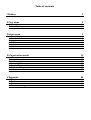
Our visualizer provides a real-time 3D rendering of your stage. It allows you to preview light
movement, colors, and every other effect available in robotic/intelligent lighting (iris, strobe, dimmer,
shutter, etc). Light beams from conventional lighting (PAR) can be visualized as well.
It is also possible to insert objects to customize your stage, such as trusses, furniture, etc. from our own
libraries of objects, or to import objects from other CAD software. With a little practice, you will be able
to reconstruct stages and venues in a very realistic way.
Note: The most accurate 3D representations come from carefully created profiles/libraries of lighting
fixtures.
The 3D visualizer includes different “modes”, each receiving the DMX signal from a different source
(software, console/desk, network, etc). The software is capable of visualizing up to 4 DMX universes
simultaneously.
The patching for the fixtures within the 3D visualizer can be done automatically if it is linked to a
software controller. If this is not the case, fixture patching must be done manually. Entire DMX
universes follow the same rule. Moreover, you can separate DMX universes within the visualizer, i.e.
Universe 1 linked to a USB/DMX-IN interface, while Universe 2 linked to Art-Net protocol.
Page 1
Visual Control
II First steps
II First steps
First steps
This chapter introduce the basics to simply use the 3D visualizer. It includes a description of the files
used to save the projects and the first steps to create a 3D stage.
1. 3D stage
3D stage
3D stages are saved with the "evs" format and can be open/saved indefinitely. Stage
dimensions, inserted objects and fixtures are also saved in these files.
It is also possible to import or export 3D stages to or from zipped files with the "Import / Export"
buttons of the "Stage" menu. Saving a 3D stage including all required files (X files, BMP or JPG files for
the textures...) and the re-open it on another computer which does not contain the same objects.
Page 2
Visual Control
II First steps
2. Your first stage
Your first stage
The following section describes how to create your first stage, introducing you to the basics of
our 3D visualizer. It will also include a description of the files used to save different projects.
Your First Stage
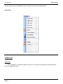
- From the “Stage” menu, select “Stage settings.” A window will open, where you can adjust the
size and color/texture for each of the walls on your stage. Notice the options available to select
individual walls, show or hide walls, repeat textures in both the X and Y axis, and change units between
metric and English.
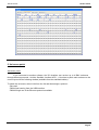
- From the “Stage” menu, select “Build mode.” This will split your 3D visualizer window into 4
sections: 3D rendering, 2D top view, 2D front view, and Object/Fixture Settings. You can control the
size and content of these sections, even hide them.
Page 3
Visual Control
II First steps
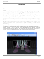
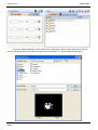
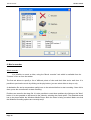
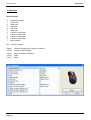
- From the “Object Settings” section click on the “Add object” button (gray cube next to the red
arrow in the picture above) to insert an object from our libraries (i.e. /Music Instrument/Drums.x)
Page 4
Visual Control
II First steps
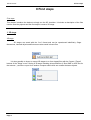
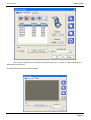
- The object will be inserted at the center of the stage. You can move this object around the 3D
stage using your mouse. Furthermore, using the object editing tools (green arrow) you can change the
position, orientation, size, color, etc. of any object selected from the list (blue arrow). These tools are
explained in later sections of the manual.
- Repeat these steps to add more objects.
Page 5
Visual Control
III User mode
III User mode
User mode
The software has 2 modes : User mode and Buil mode. The first one is for the visualization, all
features to modify the stage are disable. This chapter introduces all features dedicated to the
visualization, even if most of them are available from the other mode as well.
1. Rendering options
Rendering options
Several options are available to customize your stage and the rendering. All of then are in
"Options" menu.
Ambient lighting
It is possible to modify the intensity of Ambient lighting with the faders located on the "Options toolbar"
("View" menu, "Options toolbar").
Fog density
You can adjust the fog density on your stage. To do so, you must go to the "Light beam" menu
("Options" menu) and select "UP" or "DOWN". You can also modify the density from the "Options
toolbar" or using the keyboard shortcuts LEFT and RIGHT.
Rendering mode
It is possible to switch between "Normal" and "Powerful" rendering mode. The software starts
automatically in "Powerful" mode if your graphic card is compatible. However you can switch to the
"Normal" mode if you think that it runs too slowly.
Shadows
Page 6
Visual Control
III User mode
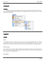
2. Resolution
Resolution
It is possible to choose from 5 different levels of screen resolution for the 3D views. This option
allows to adapt the software to the performance of your graphic card. If the rendering is too slow, select
a lower level of rendering.
3. Cameras
Cameras
Views
It is possible to move the camera with the mouse (see the buttons assignment from the "Options"
menu) if the "Move" option is selected from the "Camera" menu. Differents views (front, left...) can be
selected from the menu or from the toolbar. They can also be selected with the 1 to 5 keyboard keys.
Personal views
Up to 4 different views can be created in addition to the default ones, using the "Save" option from the
menu. The current view (position and orientation) will be then saved. Those view can be called from the
menu or with the 6 to 9 keyboard keys.
Auto rotation
Page 7
Visual Control
III User mode
An auto rotation option is available from the "Camera" menu or the 0 keboard key.
ScreenShot
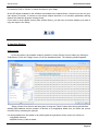
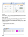
4. DMX levels
DMX levels
This is possible to visualize the DMX levels of the 4 universes by opening the following window
from the "standard" toolbar.
Page 8
Visual Control
III User mode
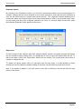
5. Universes patch
Universes patch
If not connected to another sofware, the 3D visualizer can receive up to 4 DMX universes
through different protocols : Art-Net, SandNet, Avolites ACDI...). User has to patch each universe to the
correct input with the following window (available from the standard toolbar).
To patch the universes, select it the from the list and then assign a protocol :
- Not used
- DMX signal coming from the USB Interface
- DMX through one of the Ethernet protocols available
Page 9
Visual Control
III User mode
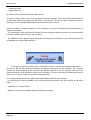
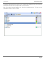
6. Movie recorder
Movie recorder
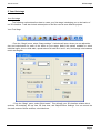
It is possible to record a video, using the "Movie recorder" tool which is available from the
"Camera" menu or from the toolbar.
The first tab allows to specify a list of different points of view and their fade and a wait time. It is
possible to preview the movie by clicking on the play button (you can select either to loop or not).
A destination file and a compression quality have to be selected before to start recording. Once this is
done, press the record button to start recording.
Positions are saved in the stage file. it is also possible to reset these positions by clicking on the "New"
button. It is also possible to add sound to the video by selecting the sound option. The attached sound
has to be played within the Windows Media Player while the video is being recorded. Make sure that
the Windows recording options are correctly setup.
Page 10
Visual Control
III User mode
The second tab allows to visualize the created video or to record a video following the
movement of the mouse.
The "Play" button starts the selected video.
Page 11
Visual Control
IV Construction mode
IV Construction mode
Build mode
This chapter introduces the second mode of the software : Build mode. The screen is split and
contains the 3D view, the "Objects settings" window, and the 2D views.
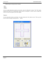
1. 2D views
2D views
Position of views
The Build mode screen is split with the 3D view, the "Objects settings" window and the 2D views.
Grid options
Page 12
Visual Control
IV Construction mode
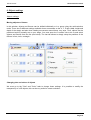
2. Stage size and color
Stage size and color
Colour and dimensions of stage (width, height and depth) can be defined within this window
(available from the "Stage" menu or from the standard toolbar).
Colour & Textures
First you must select the face or select all faces to make your stage unicolored. To change colour,
remove "x" from the "default" checkbox, then select the colour from the following window.
As for the colour, you must unselect the "Default" option to choose a texture for the walls. Select the
image (BMP or JPG) by clicking on the "..." button. You can also make your texture repeating
(horizontally and vertically) by using the "Texture repetition (X and Y)" controls.
Units
Page 13
Visual Control
IV Construction mode
3. Inserting objects
Insert objects
The software gives opportunity to insert objects from a library. Trusses, furniture and sound
system can be found there. Objects may be removed from stage at any time. To reach this library, you
need to open the following window by clicking on the "Add" button :
The library on the left side displays the available objects to be inserted. Once selected, the
object automatically appears in the visualization window. The object selected may be previewed before
Page 14
Visual Control
IV Construction mode
it is inserted. Click on "Select" to insert the object in your stage.
All the 3D objects available in the software are situated in the objects library. However you can use your
own objects (X format). It is better to use simple objects because it is a real-time application and big
objects can make the program running slowly.
If you want to insert objects coming from another library, you will have to choose whether you want to
copy the object in the library.
4. Inserting fixtures
Insert fixtures
As for the objects, the software makes it possible to insert fixtures from the library by clicking on
"Add fixture(s)" from the "Stage" menu or from the standard toolabr. The following window appears :
Select a fixture from the list and then patch it using the "Patch" button after having specified the
starting DMX address and the number of devices or by drag&drop. Make sure you select the correct
universe first by selecting the right tab.
It is also possible from the toolbar or by clicking with the right button of the mouse on a fixture to :
- copy/paste fixture(s)
- duplicate fixture (s) with a wizard
Page 15
Visual Control
IV Construction mode
- rename a fixture
- delete fixture (s)
All actions can be canceled with the UNDO button.
To select a fixture, click on it or click and draw a selection rectangle. Then, moving the selected fixture
(s) becomes possible by holding the left button of the mouse. To move a fixture to another universe,
just drag it to the corresponding tab and this will open the new universe.
When controlled by another sofware, the 3D visualizer can receive the patch informations directly. 2
modes are available :
· The "Automatic" mode will insert all fixtures from the controller patch and remove the current devices
of the 3D visualizer that are not in the controller.
· The "Manual" mode, allows to patch any fixture coming from the controller or not (several fixtures can
be patched to the same DMX address)
It is better to use this window only in "Automatic" mode to not lose all changes made before.
The list on the left side shows the fixtures informations received from the controller. The "orange"
fixtures are those available in the controller and already patched in the 3D visualizer, the "blue" are
those patched in the 3D visualizer and not in the controller. The user can select the devices he want to
insert or not. Click on "Patch" to insert the selected fixtures.
The 3 options allow to select the patch mode and 2 display options. Here they are :
· to show only the fixtures available in the controller and not patched in the 3D visualizer or the entire
patch
· "automatic" or "manual" patch
· display or not the popup window when the patch has changed
Page 16
Visual Control
IV Construction mode
5. Simple objects editor
Simple objects editor
This new tool enables you to create your own objects and reuse them later on:
Page 17
Visual Control
IV Construction mode
3 different types of objects can be created:
· Cube
· Sphere
· Cylinder
You can modify dimensions and then save them under the Microsoft X format. The "Flat" option
enables you to add 2 cm in height and to quickly create a rectangular or circular screen in shape and
reuse it over and over again in your future stages.
Textures
You can also add a texture to an object. You must unselect the "No" option to do so. Then, you just
have to select an image by clicking on the "..." button.
Page 18
Visual Control
IV Construction mode
6. Objects settings
Objects settings
Moving objects or fixtures
In this window, objects and fixtures can be shifted individually or in a group using the multi-selection
mode. There are six different settings available: three movements on the X, Y, Z axis (width, height and
depth of the stage) and also three rotating movements around these very axes. Thus, objects can be
positioned as they actually are on your stage. You must open the "Location" tab to do so and select
objects and fixtures from the list (see below). The last tab allows to simply setup the positions of the
fixtures in line, circle, rectangle...
Changing size and colour of objects
We must go to the "Size" and "Color" tabs to change these settings. It is possible to modify the
transparency of a 3D objects, this can be very useful to create a window...
Page 19
Visual Control
IV Construction mode
Fixtures list
The list is located in the "Objects" tab of the "Objects settings" window. All fixtures are listed and folders
can be created to simply classify them. The drag& drop is used to move the fixtures within the list. To
add a new folder, click on the "New folder" button from the toolbar. The up and down arrow allow to
expand or collapse the list.
To rename a fixture, double click on it and then enter the new name. It is also possible to select another
layer for the fixtures by double clicking on the layer cell and selecting a layer from the list.
The list shows information that can not be modified like the name of the profile, or the DMX address
and some options that can be modified like the beam color, the frost effect and gives the possibility to
invert PAN/TILT channels.
The 4 last columns are :
- Gel color (can be modified by clicking on the color)
- The frost effect (a frost effect is available for every fixture)
- Invert Pan
- Invert Tilt
Page 20
Visual Control
IV Construction mode
Duplicate objects
By resorting to the "Duplicate" function, you can edit in and quickly position one or several objects. For
example, imagine that you have designed a set of truss elements in circle and that you would like to
carry out the same layout at 4 meters away on the left side... The "Duplicate" function enables you to
reinsert the whole set of objects and to move them proportionally in order to get a similar layout. Now,
you can select your first group of objects (referred to as "circle 1") and by a simple mouse click, make
the following "Duplicate" menu appear on the screen.
Objects list
The list is located in the "Objects" tab of the "Objects settings" window. All objects are listed and folders
can be created to simply classify them. The drag& drop is used to move the objects within the list. To
add a new folder, click on the "New folder" button from the toolbar. The up and down arrow allow to
expand or collapse the list.
To rename an object, double click on it and then enter the new name. It is also possible to select
another layer for the objects by double clicking on the layer cell and selecting a layer from the list.
Note: It is possible to display or not each column of the list by clicking on the title bar with the right
button of the mouse.
Page 21
Visual Control
IV Construction mode
7. Layers
Layers
Like picture editing sofware, the 3D visualizer works with layers. All fixtures and objects are
included in one or several layers. By default, all inserted objects are placed in the "Objects" layer and
the fixtures in the "Fixtures" layer. However, the user can create its own layers and move objects and
fixtures from layer to layers by drag&drop.
Here are the layers properties :
· Color: A color can be defined for each layer, all objects of this layer will be displayed with this color in
the 2D views
· Visible or not: A layer can be visible or not, this makes the object/fixtures visible or not in the views
(2D and 3D)
· Lock or not: A layer can be lock and therefore all included objects and fixtures can not be moved. The
objects of a locked layers are shown in green when they are selected.
· Group: This option can be very useful when several objects have to be moved together. This feature
allows to move all the layer like a single object.
Page 22
Visual Control
IV Construction mode
For instance: Place several fixtures and the truss in the same layer and group it. Now, when a fuxture is
selected, the entire layer can be moved or rotate like a single object.
Note: Once a layer is grouped, adding a new object is not possible any more. The layer must be
ungrouped to do add or remove an object.
Page 23
Visual Control
V Appendix
V Appendix
This chapter introduces all the menus, toolbars and shortcuts of the software. The last section
shows what to check/do in case of problem with the software.
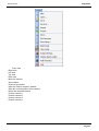
1. Menus
Menus
Menus summary
· Create a new 3D stage
· Open a 3D stage
· Save the 3D stage
· Save the 3D stage with another name
· Import a 3D stage
· Export a 3D stage
· Print
· Print preview
· Print properties
· Open the Construction mode
· Open the User mode
· Open the "Stage settings" window
· Open the "Simple objects editor"
· Add fixtures
· Exit the sofware
Page 24
Visual Control
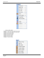
V Appendix
· Front view
· Right view
· Left view
· Top view
· Rear view
· Move the camera
· Auto rotation
· Create a screenshot
· Open the "Movie recorder" window
· Save the current position of the camera
· Delete the selected camera
· Custom camera 1
· Custom camera 2
· Custom camera 3
· Custom camera 4
Page 25
Visual Control
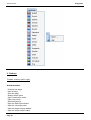
· Always visible option
· Display or not the the lower half of the screen
· Display or not the the right half of the screen
· Display the standard toolbar
· Display the camera toolbar
· Display the options toolbar
· Display the zoom toolbar
· Display de mouse toolbar
Page 26
V Appendix
Visual Control
V Appendix
· Option to save automatically when exiting the sofware
· Enable/disable the sound for any video played in the 3D stage
· Open the buttons assignment window
· Change the screen resolution
· Change the rendering mode
· Enable/Disable shadows
· Change the sofware language...
· Open the "About" window
· Start the online help
Page 27
Visual Control
2. Toolbars
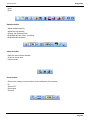
Toolbars summary (left to right)
Standard toolbar
· Create a new stage
· Open a stage
· Save the stage
· Always visible option
· Open Construction mode
· Open User mode
· Add new fixture(s)
· Open the DMX input window
· Open the universes patch
· Open the stage settings window
· Open the simple objects editor
Page 28
V Appendix
Visual Control
V Appendix
· Undo
· Redo
Options toolbar
· Adjust ambient lighting
· Adjust the fog intensity
· Change the rendering level
· Enable/disable the "laser" rendering
· Enable/disable shadows
Camera toolbar
· Open the movie maker window
· Create a screen shot
· Camera menu
Zoom toolbar
· Zoom menu (assign a zoom function to the left button of the mouse)
· Fit
· Zoom OUT
· Zoom fader
· Zoom IN
Page 29
Visual Control
3. Shortcuts
Shortcut keys
0
1
2
3
4
5
6
7
8
9
*
Esc
Automatic rotation
Front view
Right view
Left view
Top view
Rear view
Camera 1 (personal)
Camera 2 (personal)
Camera 3 (personal)
Camera 4 (personal)
Move camera
Quit the sofware
Delete
Delete selected layers, fixtures or objects
Ctrl+'N' Create a new 3D stage
Ctrl+'O' Open an existing 3D stage
Ctrl+'Z' Undo
Ctrl+'Y' Redo
Page 30
V Appendix
Visual Control
V Appendix
4. Troubleshooting
Here is a list of first things to be checked in case of problem with the sofware
· Please check that Microsoft DirectX 9b or any up to date version is installed on the computer
· Make sure that graphic cards drivers are correctly installed
. Under Windows XP, please check that the hardware acceleration is at full in the "Troubleshoot" tab of
the graphic card advanced properties window.
· If DirectX is correctly installed, enter "DXDIAG" in the "Run..." section of the "Start" menu. In the
"Dispaly" tab, please check that the following features are enabled
- DirectDraw acceleration
- Direct3D acceleration
Page 31