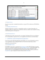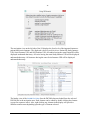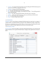
1
Laurel Bridge PowerTools User Manual Providing DICOM Connectivity for the Medical Community Laurel Bridge Software, Inc. 302-453-0222 www.laurelbridge.com Document Version: 1.0.34 Document Number: LBDC-000062-010034 Last Saved: 11/23/2015 11:55:00 AM PowerTools User Manual ©2015 Laurel Bridge Software, Inc. All Rights Reserved v1.0.34 Contents 1. PowerTools Introduction ......................................................................................................... 1 1.1. Overview ....................................................................................................................................... 1 1.2. Included Utilities ........................................................................................................................... 1 1.2.1. Graphical User Interface (GUI) Applications........................................................................................1 1.2.2. Command Line Applications ................................................................................................................2 1.3. 2. 3. 4. Important Features ....................................................................................................................... 2 Installation ............................................................................................................................... 4 2.1. Prerequisites ................................................................................................................................. 4 2.2. Installing PowerTools .................................................................................................................... 4 Getting Started ........................................................................................................................ 5 3.1. Installing a License ........................................................................................................................ 5 3.2. Activating a License over the Internet .......................................................................................... 5 3.3. PowerTools Launcher.................................................................................................................... 6 3.4. PowerTools Console ...................................................................................................................... 7 GUI Applications ...................................................................................................................... 9 4.1. Common Components .................................................................................................................. 9 4.1.1. Menu Bar .............................................................................................................................................9 4.1.2. Options Dialog ...................................................................................................................................10 4.1.3. Filter Editor Dialog .............................................................................................................................10 4.1.4. Client Routing Information ................................................................................................................15 4.1.5. Server Routing Information ...............................................................................................................16 4.1.6. Transfer Syntaxes for Presentation Context Negotiation ..................................................................16 4.1.7. Application Window Renaming .........................................................................................................17 4.1.8. External Data Dictionary Management .............................................................................................18 4.2. DICOM Client Applications .......................................................................................................... 19 4.2.1. Query Client .......................................................................................................................................19 4.2.2. Store Client ........................................................................................................................................23 4.2.3. Verification Client ..............................................................................................................................24 4.2.4. Modality Worklist Client ....................................................................................................................24 4.2.5. Study Generator ................................................................................................................................24 4.3. DICOM Server Applications ......................................................................................................... 28 4.3.1. Store Server .......................................................................................................................................29 PowerTools User Manual ©2015 Laurel Bridge Software, Inc. All Rights Reserved v1.0.34 4.3.2. Query Server ......................................................................................................................................32 4.3.3. Modality Worklist Server ...................................................................................................................32 4.3.4. Verification Server .............................................................................................................................32 4.4. 4.4.1. DICOMDIR Creator.............................................................................................................................32 4.4.2. DICOM File Editor ..............................................................................................................................33 4.4.3. DICOM Filter ......................................................................................................................................44 4.4.4. Dictionary Finder ...............................................................................................................................44 4.4.5. PDF to DICOM ....................................................................................................................................45 4.4.6. Structured Report Extractor ..............................................................................................................46 4.5. 5. DICOM Data and File Manipulation Applications ....................................................................... 32 HL7 Applications ......................................................................................................................... 48 4.5.1. HL7 Receiver ......................................................................................................................................48 4.5.2. HL7 Sender ........................................................................................................................................48 Advanced Filtering ................................................................................................................. 52 5.1. Composer Filter Action ............................................................................................................... 52 5.2. De-Identify Filter Action .............................................................................................................. 54 5.2.1. DICOM Attribute Tags to Anonymize ................................................................................................55 5.2.2. Miscellaneous Settings ......................................................................................................................56 5.2.3. Pixel Regions to Anonymize ..............................................................................................................56 5.2.4. One-Way Anonymization ..................................................................................................................57 5.2.5. Enable Re-Identification ....................................................................................................................57 5.2.6. Additional Notes ................................................................................................................................57 5.3. Re-Identify Filter Action .............................................................................................................. 58 5.3.1. 6. Console Applications ............................................................................................................. 60 6.1. Overview ..................................................................................................................................... 60 6.2. Query Client ................................................................................................................................ 61 6.2.1. Query example ..................................................................................................................................61 6.2.2. Creating a Filter File ...........................................................................................................................62 6.2.3. Format of Query Configuration File ...................................................................................................63 6.3. 7. Additional Notes ................................................................................................................................59 MWL Server................................................................................................................................. 64 Application Summary ............................................................................................................ 65 7.1. Combined GUI and Console Applications ................................................................................... 65 PowerTools User Manual ©2015 Laurel Bridge Software, Inc. All Rights Reserved v1.0.34 8. 7.2. GUI-only Applications ................................................................................................................. 65 7.3. Console-only Applications........................................................................................................... 65 PowerTools Quick Reference................................................................................................. 66 PowerTools User Manual ©2015 Laurel Bridge Software, Inc. All Rights Reserved v1.0.34 -1- 1. PowerTools Introduction Overview 1.1. Laurel Bridge PowerTools™ is a software only collection of stand-alone Windows® applications designed for the diagnosis, testing, and/or repair of DICOM® communications, for the viewing, repair, or creation of DICOM data sets and their contents, and for communications testing of basic HL7 messaging. It is suitable for use by PACS administrators, integration engineers, system testers, software developers, and others who have need of a broad range of DICOM related tools and utilities or need to test HL7 messaging. The stand-alone PowerTools programs operate as easy-to-use DICOM server (SCP) or client (SCU) applications for communication purposes, or operate as other types of applications capable of viewing, changing, creating, converting, or fixing a DICOM data set, or sending and receiving of HL7 messages. Many are provided as both GUI-based and command line-based applications, so the PowerTools utilities may be used as independent applications or scripted into a variety of situations where their capabilities are needed. These tools and utilities may be used to transmit, receive, or edit DICOM medical data or the send and receive HL7 messages. However, the PowerTools applications are not intended for diagnostic review of images or other medical data. Included Utilities 1.2. The core utilities officially included in the PowerTools suite are: 1.2.1. Graphical User Interface (GUI) Applications PowerTools Launcher – provides access to all PowerTools GUI applications. DICOMDIR Creator – creates a DICOMDIR file from a directory of DICOM images on disk (i.e. DICOM media creator). DICOM File Editor – allows the viewing, printing, and modification of a DICOM file on disk, including modification of sequence elements. Pixel data can also be viewed. DICOM Filter – filters one or more DICOM images on disk. Dictionary Finder – displays data from the DICOM data dictionary. HL7 Receiver – receives HL7 messages from an HL7 client or sender. HL7 Sender – sends HL7 messages to an HL7 server or receiver. PDF to DICOM – create DICOM Encapsulated PDFs from existing PDF files and write them to files or store them to a PACS. Query Client – queries a query SCP (or PACS) for DICOM images and can move DICOM images from the server to another location. Store Client – stores DICOM images from disk to a store SCP. Store Server – receives C-Store DICOM images from a store SCU. PowerTools User Manual ©2015 Laurel Bridge Software, Inc. All Rights Reserved v1.0.34 -2- – parses structured reports and creates mapping files for use with Laurel Bridge Software Compass™ and third-party systems. Study Generator – generates DICOM images and stores them to a store SCP. Verification Client – verification SCU to send C-Echo requests. Verification Server – verification SCP to receive C-Echo. Structured Report Extractor 1.2.2. Command Line Applications – creates a DICOMDIR file from a directory of DICOM images on disk (i.e. DICOM media creator). DICOM File Editor – dumps the contents of a DICOM file and edits a single DICOM file. DICOM Filter – filters one or more DICOM images on disk. DICOM to PDF – converts a DICOM image into a PDF. Dictionary Finder – displays data from the DICOM data dictionary. Indexer – iterates over images and indexes specified tags into a csv file. MWL Client – connects to a modality worklist SCP. MWL Server – provides a modality worklist SCP for a directory on disk. Query Client – queries a query SCP (or PACS) for DICOM images and can move DICOM images from the server to another location. Query Server – provides a query SCP for a directory on disk. Store Client – stores DICOM images from disk to a store SCP. Store Server – receives C-Store DICOM images from a store SCU. Study Generator – generates DICOM image studies and stores or writes them. Verification Client – verification SCU to send C-Echo requests. Verification Server – verification SCP to receive C-Echo. DICOMDIR Creator Note that occasionally some new tools which are not listed above may be included in intermediate release versions of PowerTools, providing an early look at upcoming additions to the suite. 1.3. Important Features All of the applications in PowerTools have been written with easy to understand interfaces. In an effort to make PowerTools even easier to use each application has built in features designed to make understanding and using the application a more natural and less frustrating experience. In all GUI applications most items on the screen have a tooltip which can be displayed by hovering the mouse pointer over the item. This tooltip displays information about the item which can be helpful for understanding the item’s purpose. For console applications, running the applications with the -h flag will display the usage for the application, listing a description of all possible flags and arguments. Using the -h flag with GUI applications will display usage information in a pop-up window, while adding the -nogui flag to many of the GUI applications will display command-line usage for the console versions of the applications. PowerTools User Manual ©2015 Laurel Bridge Software, Inc. All Rights Reserved v1.0.34 -3- Many of the GUI and command line software applications in PowerTools incorporate innovations in user interface ease-of-use and the robustness of the underlying DICOM framework or HL7 library upon which most of the Laurel Bridge PowerTools applications are built. An interesting innovation is built into the Study Generator command line tool is the inclusion of a first and last name database culled from recent U.S. Census Bureau statistics, enabling the random generation of realistic-looking patient names in roughly the same frequency with which the names occur in the general population. PowerTools User Manual ©2015 Laurel Bridge Software, Inc. All Rights Reserved v1.0.34 -4- 2. Installation To install PowerTools run the installer executable (Setup.exe) and follow the on screen directions. Prerequisites 2.1. PowerTools uses several prerequisite components that must be installed before the application can function correctly. These prerequisites consist of: - Microsoft .NET Framework 3.5 Visual C++ Runtime Libraries (x86) Windows Installer 3.1 The main installer executable (Setup.exe) will determine whether these prerequisites are needed and install them accordingly. If it is desired to install an older version of PowerTools than the currently installed version, or to reinstall the current version, it is necessary to first uninstall the current version. 2.2. Installing PowerTools After installing the prerequisites the PowerTools installer (PowerTools.msi) will run. For machines with an older version of PowerTools installed this installer will upgrade any previous installation while maintaining any current configuration settings. PowerTools User Manual ©2015 Laurel Bridge Software, Inc. All Rights Reserved v1.0.34 -5- 3. Getting Started 3.1. Installing a License The first step after launching PowerTools is to install a license. Running the PowerTools Launcher application from the start menu for the first time will bring up a dialog allowing a license to be installed. When the About Laurel Bridge PowerTools dialog appears, click the Install License… button, browse to the license file, and hit OK. Information on the status of the license, including when it expires, can be found on this dialog available at any time by clicking Help > About… in any PowerTools GUI application. The license works on a per user basis; each user will need to install a valid license to run any of the utilities. 3.2. Activating a License over the Internet Clicking the Activate License… button will open the License Activation form. You will need to provide a 16-digit product serial number (Product S/N) to activate your license. All fields on the form should be filled out. When the License Activation dialog first appears, it will attempt to contact the Laurel Bridge license server and pre-populate the form with as much information as it has available. If PowerTools cannot reach the license server you will be presented with an information message describing which fields need to be entered to activate your license on the Manual Product Activation interface on the Laurel Bridge Customer Access web page here: https://www.laurelbridge.com/product_activation.php PowerTools User Manual ©2015 Laurel Bridge Software, Inc. All Rights Reserved v1.0.34 -6- Note that if PowerTools does not have internet access you will need the 16-digit Activation Request Code (ARC) from the Manual Product Activation (see above). On that form enter your 16-digit Product Serial Number and the 16-digit Activation Request Code. After completing the steps on the web activation form you can download a fully activated PowerTools license. Once downloaded, use the Install License... button on the About dialog to install your activated license. If you only have a MAC address you will need a valid login to www.laurelbridge.com to proceed. For assistance with this process, please send email to: [email protected] 3.3. PowerTools Launcher The PowerTools Launcher can be found in the start menu and provides access to all of the PowerTools GUI applications. Each application has a brief description available by selecting the application in the list. Double-clicking an application or selecting it in the list and clicking Launch will begin execution of that application. All PowerTools applications (except for the Launcher) can have multiple copies running at once. Information about PowerTools and access to license information can be accessed by clicking the About PowerTools button. The user manual you are reading is available via the User Manual button. PowerTools User Manual ©2015 Laurel Bridge Software, Inc. All Rights Reserved v1.0.34 -7- 3.4. PowerTools Console The PowerTools Console can be found in the start menu and provides access to all of the PowerTools command-line (console) applications. The console will launch and set the working directory to the installation folder for PowerTools. It will also add the PowerTools installation folder to the Path temporarily for the session. Running the predefined PowerTools console command list will display all executables as well as any example configuration files and documentation files (see below). Running the command dir *.exe will display all of the executables in the directory. Running any of the applications with the -h flag will display the command-line usage statement for that application. Many of the applications are combined GUI and console applications. For these combined applications, the -h flag will display usage information for the GUI version, while using the -h and -nogui flags together will display usage information for the console version. For GUI-only and console-only applications, the -h flag is all that is needed to display usage information. PowerTools User Manual ©2015 Laurel Bridge Software, Inc. All Rights Reserved v1.0.34 -8- Example output produced by running the PowerTools console command list. PowerTools User Manual ©2015 Laurel Bridge Software, Inc. All Rights Reserved v1.0.34 -9- 4. GUI Applications Common Components 4.1. There are several components that are common to many or all of the PowerTools GUI applications. Learning to use these components will make interacting with the PowerTools GUI interface much easier. 4.1.1. Menu Bar The Menu Bar may vary slightly between GUI applications; however the following commands are present in almost every PowerTools application. File > Exit – Exits the application. Tools > Options – Displays options for the application. Many applications have settings to specify: o Logging o Filtering Tools > Revert To Factory Settings – Reverts all configuration settings for the application back to their original defaults. Help > User Manu – Opens the PDF user manual document for viewing. Help > Support Request – Opens the Send Support Request dialog so a user can send a request for support directly from the running application. Help > Feedback – Opens the Send Feedback dialog so a user can send feedback to Laurel Bridge Software directly from the running application. Help > About – Shows the About dialog for PowerTools information and for license management, including support for license installation and activation. Help menu options PowerTools User Manual ©2015 Laurel Bridge Software, Inc. All Rights Reserved v1.0.34 - 10 - 4.1.2. Options Dialog The Options Dialog provides two common features shared by most of the GUI applications: logging and filtering. Logging o Enable Logging – enables/disables logging for the application. o Log Level – selects the amount/intensity of the logging (useful for debugging). o View Log – click to open the current log for the application. o View Log Directory – click to open the directory where the logs are stored. Filtering (only present in the Options Dialog for client and server applications) o Enable Filtering – enables/disables filtering for the application’s input/output DICOM messages. o Edit Filters… – opens the Filter Editor Dialog to edit the filters for the application. OK – exits the Options Dialog and saves any changes. Cancel – exits the Options Dialog without saving. 4.1.3. Filter Editor Dialog The Filter Editor Dialog provides the ability to create filters which will modify DICOM communication or DICOM files on disk. Each filter is chained together to the next one and all are executed in order on a DICOM data set—a collection of DICOM elements. These elements comprise the header of each DICOM image filtered (currently pixel data cannot be filtered). PowerTools User Manual ©2015 Laurel Bridge Software, Inc. All Rights Reserved v1.0.34 - 11 - Key components in the Filter Editor Dialog include: – changes the filters that are being edited (for example, “Inbound Filters” in the image above represents all incoming DICOM communication to the application). Import… – imports a filter configuration from disk (allows configurations to be shared between PowerTools utilities). Export… – exports a filter configuration to disk (allows configurations to be shared between PowerTools utilities). Filter – the list of filters in order of execution (filters are chained together) to be applied to the DICOM communication. The buttons at the bottom of the filter list allow filters to be added, removed, moved up in execution order, and moved down in execution order. Conditions – a list of conditions to check against to decide whether or not to apply actions. Conditions are checked in order as listed—to change the order click the up or down buttons for the condition. Actions – a list of actions to perform on the DICOM data if the conditions were true. Actions are applied in order as listed—to change the order click the up or down buttons for the action. Match All / Match Any – selects whether all conditions in the current filter must match before applying actions or whether only one condition is required to match. OK – exits the Filter Editor Dialog and saves any changes. Cancel – exits the Filter Editor Dialog without saving. Type PowerTools User Manual ©2015 Laurel Bridge Software, Inc. All Rights Reserved v1.0.34 - 12 - Filter Conditions DICOM Tag – condition which checks a DICOM element for certain requirements. DICOM Tag allows specification of a DICOM tag and an operator to check against the tag’s value. In this example, if [Patient’s Name] [Contains] [XXX] then the condition is true. Filter Actions Change Case De-Identify – Composer – supports – changes the alphabetical case of a DICOM element’s value to either all uppercase or all lowercase. In this example [Patient’s Name] is changed to all [Lower]case. provides a sophisticated mechanism to remove and replace certain attributes within a DICOM dataset that may lead to patient identification. For details on use of the De-Identify filter action, see section 5.2, De-Identify Filter Action, below. the merging and splitting of elements. It can also be used to manipulate DICOM sequence elements with ease. It uses regular expressions to parse values from DICOM tags and combine the values into other DICOM tags. For example, it can take parts from two different tags and combine them to make a new value in a third tag. Regular expressions are specified to parse each input tag and substitution patterns determine how the output tags are constructed. For details on advanced use of the Composer filter action, see section 5.1, Composer Filter Action, below. In the Input Elements table, specify the tags and how the regular expressions should parse each value into groups – the regular expressions go into the Input Patterns column. The groups that are produced are specified in the Output Patterns column of the Output Elements table. The first match in the first input element is referred to as “${1.1}”, the second match in the first input PowerTools User Manual ©2015 Laurel Bridge Software, Inc. All Rights Reserved v1.0.34 - 13 - element is “${1.2}”, and the third match in the second input element would be “${2.3}”, and so on. The Output Elements specify what parts of the input elements to combine and how to combine them; note that the parts can be used multiple times and may also be combined them with plain text. Copy – Execute Find/Replace Insert/Overwrite Mapping List copies one DICOM element’s value to another DICOM element. In this example the value in [Patient’s Name] is copied over the value for [Patient’s Birth Name]. – executes the C# code contained in the code file provided. This option is provided for special cases where no other actions can perform the needed filtering. If this action is required please contact Laurel Bridge support. – checks the value of the DICOM element specified for the given text (or regular expression) and replaces it with the substitute text (or regular expression substitution string). In this example the value in [Patient’s Name] is checked for instances of the text [miner] and any such instances are replaced with the text [minner]. – inserts a new DICOM element or overwrites it if it already exists in the DICOM data set. In this example the [Patient’s Weight] element is inserted into the DICOM data set and given a value of [200]. Any previous value if it existed is overwritten. – performs a mapping based upon the arguments given. This is very useful if a large number of DICOM data sets need to be changed depending upon a large list of values for particular DICOM elements in those data sets. Arguments for this action are as follows: o Mapping File – a list of values separated by Delimiter. Each row of values should contain as many columns as is specified by the largest Column listed. o Delimiter – the character used to separate values in the Mapping File. o No Match Action – the action to perform if unable to find a match for the current DICOM data set using the Match Tag List selected. PowerTools User Manual ©2015 Laurel Bridge Software, Inc. All Rights Reserved v1.0.34 - 14 - o Match Tag List – a list of tags to match against the current DICOM data set being filtered. These represent the first columns of values in the Mapping File. o Replace Tag List – a list of tags to replace with the values given in the Mapping File should a match occur. In this example the mapping file [C:\mapping_list.csv] should contain five columns of values each separated by a [Comma]. If there is no match the action will [Continue]. The first column of values corresponds to [Accession Number] and the second column of values corresponds to [Study Instance UID]. The third column of values corresponds to [Patient’s Name], the fourth to [Patient ID], and the fifth to [Study Date]. When a new DICOM data set arrives to be filtered the values for the two DICOM elements in the data set described by the first two columns will be compared against every row in the Mapping File for a match. If a match is found then the replace values in columns 3-5 will be inserted/overwritten for the Replace Tags List. These DICOM elements will only be overwritten in this example if a match is found. Here is an example row for this case: [1.2.3.4,3.3.1.2.4,JOHN,7.6.5.4.3.2.1,20091215] For this row to apply, the DICOM data set passed in must have its Accession Number set to “1.2.3.4” and its Study Instance UID set to “3.3.1.2.4”. If this matches, then the Patient’s Name will be changed to “JOHN”, the Patient ID will be changed to “7.6.5.4.3.2.1”, and the Study Date will be changed to “20091215”. – moves one DICOM element’s value to another DICOM element. In this example the value in [Patient’s Weight] is moved to the value for [Patient’s Size] even if there is currently a value for [Patient’s Size]. [Patient’s Weight] will no longer exist in the DICOM data set. Move PowerTools User Manual ©2015 Laurel Bridge Software, Inc. All Rights Reserved v1.0.34 - 15 - New UID Pad Remove – removes the given DICOM element from the DICOM data set. If the Only If Empty check box is selected then the element will only be removed if its value is empty – replaces the UID for the DICOM element listed with a new generated one. In this example the value of [Device UID] will become a newly generated UID. If the DICOM element did not exist previously it will be created. – pads a DICOM element’s value to the desired length with the given character. In this example [Patient’s Name] will be changed to be [25] characters long by inserting the [*] character on the [Left] side of the current value for [Patient’s Name] as many times as necessary to pad to [25] characters long. If the current length of the DICOM element selected is already long enough then nothing is changed (the value is not cropped). or zero characters in length. In this example [Patient ID] is removed from the DICOM data set but [Only If Empty]. – removes the specified character sequence from the beginning and/or end of a DICOM element’s value, if present. In this example the character sequence “abc” is removed from the beginning of the [Patient’s Name] value. Note that multiple instances of the character sequence could be removed. For example, if the [Patient’s Name] DICOM element contains the value “abcabcSteve”, the resulting value will be “Steve”. Trim 4.1.4. Client Routing Information All client GUI applications have the same interface for specifying routing information. Client AE Title – the Application Entity title for the running application (client). Client IP Address – the IP address to use on the local machine when sending data. PowerTools User Manual ©2015 Laurel Bridge Software, Inc. All Rights Reserved v1.0.34 - 16 - – the port to use on the local machine when sending data (select Allow Any to choose the next available port). Server AE Title – the Application Entity title of the server machine to which to connect. Server Host – the host name or IP address of the machine to which to connect. Server Port – the port number on the server machine to which to connect. Verify – click this button to send both an ICMP Ping and a DICOM C-Echo test to the server. If logging is enabled then a log of the C-Echo will be recorded. A check means that the verification was successful; an X means that it was not. Client Port 4.1.5. Server Routing Information All server GUI applications have the same interface for specifying routing information and for restricting which clients can connect. – reject any connecting clients that do not have the specified Application Entity title (select Allow Any to accept a client using any AE title). Client IP Address – reject any connecting clients that are not connecting from the specified IP address (select Allow Any to accept a client connecting from any IP address). Client Port – reject any connecting clients that are not connecting using the specified port number (select Allow Any to accept a client connecting using any port number). Server AE Title – reject any connecting clients that are not attempting to connect to the server with the specified server Application Entity title (select Allow Any to accept a client regardless of the AE title it is using for the server). Server Host – the IP address on the local machine on which to establish the server. Server Port – the port number on the local machine on which to establish the server. Client AE Title 4.1.6. Transfer Syntaxes for Presentation Context Negotiation Some client and server applications provide the ability to select what transfer syntaxes should be included in presentation context negotiation. This ability allows a client application to force DICOM communication to a server to use a specific transfer syntax or to give preference to certain transfer syntaxes. It also allows a server to accept only certain transfer syntaxes from a client or to give preference to certain transfer syntaxes. PowerTools User Manual ©2015 Laurel Bridge Software, Inc. All Rights Reserved v1.0.34 - 17 - All supported transfer syntaxes are initially included in the drop down box. If the add button is clicked then the transfer syntax selected in the drop down box will be moved to the list below. Transfer syntaxes in the list can be removed and moved up or down in priority. The transfer syntaxes at the top of the list will be given greater priority when negotiating presentation contexts and the transfer syntaxes at the bottom of the list will be given lower priority. 4.1.7. Application Window Renaming All of the client and server GUI applications have the ability to rename the application window title bar, which can be helpful when running multiple instances of the same application. Entering a new name in the Store Server application renaming dialog The renaming dialog is activated by hitting the F2 key (the default Windows file and dialog renaming key shortcut) when the application is open and has focus. PowerTools User Manual ©2015 Laurel Bridge Software, Inc. All Rights Reserved v1.0.34 - 18 - application before and after window renaming. Note the text in the title bar has changed from “Store Server - Laurel Bridge Software” to “Store Server 5” Store Server Note that the new name in the title bar only persists until that application instance exits. The next time the application is run it will have the original, standard title in the title bar. This renaming feature is also available when starting any of the GUI applications that support renaming at the command line, and is particularly helpful when scripting the startup of a number of collaborating applications. This is done using the -name command line switch. An example of starting up one renamed Store Server and three renamed Study Generator instances is provided in the demo batch script example_gui_renaming.bat in the PowerTools installation directory. 4.1.8. External Data Dictionary Management The Dicom File Editor and Dictionary Finder applications provide access to functionality that selects and manages an external data dictionary. When activated via an options setting, a status indicator appears in the upper right of the main application window. Indicates that no external data dictionary is loaded A DICONDE external data dictionary is loaded A user-customized external data dictionary is loaded When the indicator is visible, clicking on it opens the external data dictionary manager, where the user is presented with a four choices of the Type of dictionary to load: None – do not load any external data dictionary. Blank – create an empty text file and load it as the external data dictionary. Built-in DICONDE Dictionary – load a standard DICONDE data dictionary. User-selected Dictionary – enable the selection of a data dictionary file. When the User-selected Dictionary option is selected, the file browser is activated so the user can select a data dictionary File. PowerTools User Manual ©2015 Laurel Bridge Software, Inc. All Rights Reserved v1.0.34 - 19 - Buttons on the Select External Data Dictionary dialog do the following when clicked: 4.2. Reset – sets the selected Type to None and clears the File entry field. Show Folder – opens the default application folder containing the current and any backup external data dictionaries. OK – saves the current options for external data dictionary. If the data dictionary in use was changed, a backup copy of the previous data dictionary is created in the same directory. Cancel – cancels any changes made to the selected options. DICOM Client Applications PowerTools provides several DICOM client applications which connect to a DICOM server on a remote machine and transmit DICOM communication. The advanced functionality of these applications is discussed below. 4.2.1. Query Client Query Client can query a query SCP containing a database of DICOM images and request information about certain images. It has both console and GUI versions. Using the command-line interface, query parameters can be specified either directly using the −q flag, or via a configuration file. For example, a command line query for all patients that have a Patient ID of “112233”, and returning those values plus Accession Number and Referring Physician, looks like this: QueryClient [other params] -q 0008,0050= -q 0008,0090= -q 0010,0020=112233 Instructions for using a configuration file to perform queries are contained in the example configuration file (QueryClientExample.cfg) found in the PowerTools installation directory. Query Client includes three query modes, Find, Move, and MWL described by Query Type, and two search methods, Relational and Hierarchical, described by Query Method. Find mode queries a query SCP for DICOM data sets which contain DICOM elements which match the tags selected in the GUI. Tags with an empty value will be populated upon response from the server. PowerTools User Manual ©2015 Laurel Bridge Software, Inc. All Rights Reserved v1.0.34 - 20 - Move mode queries a query SCP in the same way, but instead of returning the found DICOM elements the entire DICOM data sets which match are sent to the Move destination, described by the Move AE Title (the query server should have a mapping for this AE title so that it knows where to send the DICOM images). Relational and Hierarchical search methods support queries to PACS of the corresponding query architecture. MWL mode enables a mechanism for performing Modality Worklist queries using the Query Client user interface. When the application is in MWL mode, Modality Worklist queries of arbitrary depth can be crafted in the Query Tag List. Key components of the Query Client user interface include: – the information model of the query server (Study, Patient, or PatientStudy). Query Level – the level at which to query on the server (Patient, Study, Series, or Image). Query Tag List – a list of tags with which to query the query SCP. Values can be edited to request a match, and if left blank that value will be filled in upon return. Info Model (Root) PowerTools User Manual ©2015 Laurel Bridge Software, Inc. All Rights Reserved v1.0.34 - 21 - Query Tag List in Find Mode Query Tag List in MWL Mode The green plus and red minus buttons are used to Add a tag to the list or to Remove the selected item, if any, from the list of items. The green up and down arrows move the selected item up or down in the list. When in MWL mode where there Query Tag List can be in a tree layout, the Add button will add a tag as a child of the currently selected item in the list, or at the top level of the list if no item in the list is selected. In Find or Move mode, the Add button simply adds a tag to the list. In all modes, the Remove button will immediately remove any item that has no child items. In MWL mode, the Remove button will cause a prompt for confirmation before removing a selected item and all of its child items if that item has one or more child items. A context menu pops up when an item in the list is right-clicked. Depending on the current mode, an item can be added, added as a child of the selected item, removed along with any child items, or the entire list can be cleared. Context menu in Find/Move mode PowerTools User Manual Context menu in MWL mode ©2015 Laurel Bridge Software, Inc. All Rights Reserved v1.0.34 - 22 - Use Default Tags – populates the list with default query tags appropriate to the currently selected mode. Find/Move queries have a Minimal and Standard set of defaults, while MWL queries have Minimal, Standard and Extended default sets. Predefined default tag sets are available. (2 for Find/Move, 3 for MWL) Find/Move/MWL Query – clicking this button initiates a C-Find, C-Move or Modality Worklist query operation to the query SCP using the specified information. Query Timeout – the amount of time in seconds to wait before timing out the query (times out after no response has been received for the number of seconds specified). – if checked then the maximum number of queries returned is limited to the value specified. Limit Max Query Results The Options dialog in the Query Client provides Logging and Filtering support, as well as a convenient interface to configure Query Timeout and to Limit Max Query Results returned. PowerTools User Manual ©2015 Laurel Bridge Software, Inc. All Rights Reserved v1.0.34 - 23 - 4.2.2. Store Client The Store Client is used to perform DICOM image store operations, and has both console and GUI versions. Once DICOM images have been selected and the Send button is clicked, images are sent to the selected DICOM store server. Sending can be canceled at any time by clicking the Cancel button. Upon completion, an optional status report of the completed store operation can be viewed. Advanced settings in Store Client are described below. – if checked and an error occurs during the transmission of a single DICOM image then the images that have not yet been sent will still be attempted. Fail On Rejected Presentation Context – if checked and presentation context negotiation is unsuccessful for an image then the store attempt will fail. Use Separate Associations For Each Image – if checked then each image will be sent using a separate association. By default all images are sent together in a single association. This option could be useful for load testing of a server. Delay each store by - optionally define a delay to be used between each image being sent, from 0 to 99.999 seconds. Hide Report On Successful Send – If all images are sent successful and this is checked then the status report shown at the conclusion of the send will not be displayed. Context Mode – the mode with which to negotiate presentation contexts using the Desired Client Transfer Syntaxes For Presentation Context Negotiation List . o As Encoded Transfer Syntax Only – sends all images in their current transfer syntax. If the SCP will not accept an image’s transfer syntax then that image will not be sent. o As Encoded Else SCP Preferred Transfer Syntax – attempts As Encoded Transfer Syntax Only, and if that fails then the image will be sent in whatever transfer syntax the SCP prefers. o As Encoded Else SCU Preferred Transfer Syntax – attempts As Encoded Transfer Syntax Only, and if that fails then the image will be sent using the desired client transfer syntaxes for presentation context negotiation list if possible (the transfer syntaxes at the top of the list will be given a higher priority). o SCP Preferred Transfer Syntax Only – images will be sent in whatever transfer syntax the SCP prefers. o SCU Preferred Transfer Syntax Only – images will be sent using the desired client transfer syntaxes for presentation context negotiation list if possible (the transfer syntaxes at the top of the list will be given a higher priority). Continue Sending On Error PowerTools User Manual ©2015 Laurel Bridge Software, Inc. All Rights Reserved v1.0.34 - 24 - 4.2.3. Verification Client Verification Client connects to a remote server and checks to see if it is currently running (both ICMP ping and DICOM C-Echo tests are performed). Its functionality is available in every client application and will not be described further. 4.2.4. Modality Worklist Client Modality Worklist Client provides a command-line interface to common functionality of a modality worklist client suitable for testing, troubleshooting and as a developer tool. Using the command-line interface, query parameters can be specified either directly using the −q flag, or via a configuration file. For example, a command line query for all patients that have the word “Simpson” in their name and have a Patient ID of “112233”, and returning those values plus Accession Number and Referring Physician, looks like this: MwlClient [other params] -q 0008,0050= -q 0008,0090= -q 0010,0010=*Simpson* Instructions for using a configuration file to perform queries are contained in the example configuration file (MwlClientExample.cfg) found in the PowerTools installation directory. The GUI version of the Query Client supports top-level Modality Worklist queries, with future enhancements planned. 4.2.5. Study Generator The Study Generator uses customizable Patient Name, Date of Birth, Sex, Modality and Study Date attributes to generate and store one or more DICOM images to a specified Store Server profile, comprised of Host, Port, Called AE and Calling AE. The application supports defining up to 32 of these Store Server profiles to simplify repeated testing on multiple destinations. Any number of additional DICOM tags (Extra Tags) can be specified, and the user can specify the Number of Studies, Series per Study, Images per Series, Image Size, and whether or not to Use Separate Association per Study, Series or Image. Clicking on the Generate button starts the store job, which can be canceled at any time by clicking the Cancel button. If the Store Studies in Parallel option is checked, the Study Generator will attempt to concurrently store each of the requested Number of Studies, up to a limit determined by the Windows operating system. There also may be an even lower limit for the maximum number of concurrent stores (i.e., associations) depending on the specific store server being targeted. The application attempts to warn the user when these limits are being exceeded, although some experimentation may be required. An optional Background Image can be selected that will be used as the image content for all generated images. When present, the background image will contain a visible watermark PowerTools User Manual ©2015 Laurel Bridge Software, Inc. All Rights Reserved v1.0.34 - 25 - indicating that the image is a “SAMPLE.” When not present, a solid black background will be used. An optional textual Tag Overlay of study information also can be displayed. Any image in one of the more command image formats (JPEG, PNG, BMP, GIF and TIFF) can be used as a Background Image. A selection of example images for a variety of modalities is in the backgrounds subfolder in the PowerTools installation directory. If the Extra Tags for Columns and Rows are loaded after the Background Image is selected, their values will be auto-sized to the dimensions of the Background Image. See below for information on the Load Extra Tags options menu. Study Generator main user interface One or more Store Server Profiles can be defined, with the list of profiles each containing a Host, Port, CalledAE and CallingAE persisting across uses of the Study Generator. To add a new store server profile, click the button and enter a new profile name into the dialog: PowerTools User Manual ©2015 Laurel Bridge Software, Inc. All Rights Reserved v1.0.34 - 26 - Once a profile has been added to the list of profiles, its values can be directly edited in the main GUI screen by first selecting the desired profile name from the list and then editing the four values underneath. Note that when adding a profile, the Host, Port, CalledAE and CallingAE values for the currently selected profile will be copied into the newly added profile. To delete a store server profile, select the desired profile in the list and click the confirm deletion of the profile. button, and There is no direct way to rename a store server profile. To effectively rename a profile, select the profile to be renamed (e.g., “Old Profile”), add a new profile (e.g., “New Profile”) with the desired new name, and then delete the first profile (i.e., delete “Old Profile”). The Tools menu provides access to the Options dialog and to a variety of time-saving shortcuts. PowerTools User Manual ©2015 Laurel Bridge Software, Inc. All Rights Reserved v1.0.34 - 27 - Tools o Options – launches the Options Dialog (see below). o Load Extra Tags – provides five convenient selections that will populate the Extra Tags list with the indicated tags. Note that a tooltip will pop up for each of these selections, providing information about the tags that will be added. o Clear Extra Tags – clears all tags from the Extra Tags list. o Revert To Factory Settings – resets the application to its initial settings. When loading the Bits Allocated and Stored tags, the user can indicate generation of 8 or 16 bit images by setting the appropriate value in the Bits Allocated tag. If not indicated, 8 bit images are generated. The Options dialog in the Study Generator provides support for Logging, as well as two additional settings. By selecting Show group & element numbers in Extra Tags list, the group and element numbers are displayed in the drop down list of Extra Tags to support locating tags by group and element number in addition to tag name. PowerTools User Manual ©2015 Laurel Bridge Software, Inc. All Rights Reserved v1.0.34 - 28 - Extra Tags with no group and element numbers displayed Extra Tags with group and element numbers displayed Selecting Delay each store by supports inserting a delay of a configurable number of seconds between each store operation. Each store can be delayed by exactly or up to a desired number of seconds, from 0.0 to 99.999 seconds. The console version of the Study Generator makes use of a configuration file that controls generation of a variety of Patient, Study, Series and Image tags. A number of built-in functions support generation of random values for UID, date, time, name and gender. Detailed instructions are contained in the example configuration file (StudyGeneratorExample.cfg) found in the PowerTools installation directory, along with a small, example DICOM file (mr-knee.dcm) that can be used as a template for generating studies. 4.3. DICOM Server Applications PowerTools provides several DICOM server applications which receive connections from a DICOM client on a remote machine. The more advanced functionality of these applications is discussed below. PowerTools User Manual ©2015 Laurel Bridge Software, Inc. All Rights Reserved v1.0.34 - 29 - 4.3.1. Store Server The Store Server provides DICOM SCP functionality. Received images are displayed in a grid display, with each row in the grid representing all images received within the same association. Rows can be expanded to show a sequence of cards displayed, each with a summary of DICOM header tags and a thumbnail view of the image, if any. Within each card, if an image contains multiple frames, the Number of Frames is displayed. When the thumbnail image is clicked, it will be opened in the Dicom File Editor for viewing and editing. Main user interface screen of the Store Server. PowerTools User Manual ©2015 Laurel Bridge Software, Inc. All Rights Reserved v1.0.34 - 30 - Clicking on a thumbnail image will open the underlying DICOM image file in the Dicom File Editor. The Number of Frames in a multi-frame image is shown. For DICOM image files that do not contain viewable image data, a “No Image” indicator is displayed on the Image Thumbnail: The No Image indicator. PowerTools User Manual ©2015 Laurel Bridge Software, Inc. All Rights Reserved v1.0.34 - 31 - Large numbers of image and log files can be generated in the process of running the Store Server. To assist with file system cleanliness, when the application is exited the user is presented with a dialog offering the option of deleting these image and log files before exiting. If the Don’t ask me again checkbox is checked, this dialog will not appear again unless the feature is reset in the Options dialog. The Clear All Before Exit dialog of the Store Server. Advanced settings in Store Server are described below. Automatically Start Server On Application Start – if checked then the server will attempt to start immediately upon application startup. Don’t ask to clear all on exit - if checked then the “Clear All On Exit” dialog will not appear on application exit. Favor SCU Proposed Presentation Contexts – if checked then the connecting SCU will be given preference when negotiation presentation contexts. If unchecked then Store Server will negotiate presentation contexts based upon its Supported Server Transfer Syntaxes For Presentation Context Negotiation List. The Transfer Syntaxes for Presentation Context Negotiation setting (section 4.1.6) that is common in a number of client and server applications has been extended in the Store Server with the ability to add one or more custom transfer syntax entries to enable graceful handling of a wide variety of non-standard and incorrect transfer syntax values. – by selecting this option in the drop down list and clicking the add button, the user can enter any desired transfer syntax UID and Name. The list automatically prevents duplicate or blank UIDs from being entered. Add Custom Transfer Syntax UID and Name PowerTools User Manual ©2015 Laurel Bridge Software, Inc. All Rights Reserved v1.0.34 - 32 - Extended Transfer Syntax settings management in Store Server 4.3.2. Query Server Query Server provides a command-line interface to a query SCP for a directory of DICOM files on disk. 4.3.3. Modality Worklist Server Modality Worklist Server provides a command-line interface to common functionality of a modality worklist server that accesses its data from a directory on disk, and is suitable for testing, troubleshooting and as a developer tool. 4.3.4. Verification Server Verification Server can be used to provide a very simple Verification SCP to test a verification SCU. Its functionality is present in every server application and will not be described further. 4.4. DICOM Data and File Manipulation Applications PowerTools provides DICOM applications which modify one or more DICOM files on disk as well as applications used to manage DICOM data. The advanced functionality of these applications is discussed below. 4.4.1. DICOMDIR Creator DICOMDIR Creator takes as arguments an Image Directory where DICOM images are located (may also be contained in subdirectories) and a DICOMDIR File Name (usually DICOMDIR). The application then creates a directory/image hierarchy from the images found in the image directory and creates a DICOMDIR file using the information gathered which is placed in the Image Directory upon completion. Results are shown in the Results list. PowerTools User Manual ©2015 Laurel Bridge Software, Inc. All Rights Reserved v1.0.34 - 33 - Also, please note the following when creating a DICOMDIR: 4.4.2. DICOM File Editor provides a three-tabbed view for inspecting DICOM files: a tabular view of the header contents, a hex viewer, and an image viewer for the pixel data. It is recommended to set the DICOM File Editor as the default viewer for .DCM files in Windows to enable faster viewing/editing of image files. Some advanced settings for this application are described below. DICOM File Editor The DICOM File Editor menu bar has several options unique to the application. PowerTools User Manual ©2015 Laurel Bridge Software, Inc. All Rights Reserved v1.0.34 - 34 - File Menu File o New – creates a new DICOM data set for editing. o Open… – opens a DICOM file from disk. This functionality can also be performed by dragging a DICOM file from Windows Explorer into the main view of the DICOM File Editor. o Open Folder… – opens a folder of DICOM files from disk. This functionality can also be performed by dragging a folder of DICOM files from Windows Explorer into the main view of the DICOM File Editor. o Recent Files – provides a convenient list of recently opened files. o Import From > LBS CFGGroup… – similar to Open, but uses a Laurel Bridge data file instead of a DICOM file. o Export To > LBS CFGGroup… – saves the currently open DICOM data set as a Laurel Bridge data file. o Export To > Text Document… – dumps the currently open DICOM data set to a text file in text format. o Save – saves the current DICOM data set to a file. o Save As… – saves the current DICOM data set to a file specifying the file name and transfer syntax in which to save the image. o Save Image As – saves the currently displayed image frame on the Image panel as a regular image (BMP, GIF, JPEG, PBM, PGM, PNG, PPM, TIFF). For multiframe images, the current frame will be saved to one of these formats. Additionally, for multi-frame images only, the complete multi-frame image can be saved as an Animated GIF at a 10 fps rate. o Save Header As Text – saves the header of the current DICOM data set as a plain text file, specifying the file name of the saved file. o Print Preview… – shows a preview of what will be printed if the current DICOM data set is printed. o Print… – prints the current DICOM data set to a printer (without pixel data). PowerTools User Manual ©2015 Laurel Bridge Software, Inc. All Rights Reserved v1.0.34 - 35 - o Close – closes the currently open data set, if any. o Clear – clears the list of DICOM data sets in the navigation view. o Exit – exits DICOM File Editor. Tools Menu Tools o Options – launches the Options Dialog (see below). o Find in Open DICOM DataSet... – launches the Find dialog that enables search operations in the open data set. o Clear Find Highlighting – clears the highlighting that results from a Find All operation in the Find dialog. o Filter Open DICOM Data Set – launches the Filter Editor Dialog and applies any filters to the currently open DICOM data set. o Copy Path of Open File to Clipboard – copies the complete path of the open DataSet file to the system Clipboard. o Revert To Factory Settings – in addition to the default reset behavior, selecting this will clear the Recent Files list and the list of recent search terms in the Find dialog. PowerTools User Manual ©2015 Laurel Bridge Software, Inc. All Rights Reserved v1.0.34 - 36 - The Options Dialog in DICOM File Editor allows the specification of several unique settings. – Checking this option will enable logging for DICOM File Editor use. For more description of logging, see the description of the Options Dialog in section 4.1.2. Value Separator Characters(s) – specifies the character(s) to use to separate multi-valued elements in the main value display. o Comma and Backslash – a multi-valued element will appear as [a/b] or [1,2] o Newline – a multi-valued element will place each new value on a new line. Save Files in Ch 10 Format – when checked, data sets will be saved in Chapter 10 format. Invent Group 2 Data – when checked, group 2 data will be invented if needed. Read Invalid VR as Implicit – an advanced and rarely needed option, it enables data sets containing a variety of errors to be opened and viewed. Show external data dictionary indicator – when checked, the external data dictionary indicator is displayed on the menu bar (section 4.1.8). Manage - when clicked, the Select External Data Dictionary (section 4.1.8) dialog pops up, enabling selection and management of external data dictionaries. Show names for well-known UIDs – causes the names of any well-known UIDs to be displayed in the header view tab rather than the UID strings themselves. The original UID will be displayed in a tooltip when the name is hovered over with the mouse. Items shown in Recent Files List - determines how many recently opened files will be listed in the Recent Files menu item. Enable Logging PowerTools User Manual ©2015 Laurel Bridge Software, Inc. All Rights Reserved v1.0.34 - 37 - The Find Dialog in the DICOM File Editor provides searching within the open data set. The “Find what” field maintains a list of recently used search term. Clicking Find Next will search in the selected search Direction (Up or Down), while clicking Find All will highlight all matching elements in the data set. Selecting Match whole word will limit search results to matches that have whitespace or are at the start or end of a field rather than an arbitrary partial match. Selecting Match case will make the search case-sensitive. Highlighting after a Find All operation for the search term “study” When Use wildcards is selected, a limited set of wildcard notation is available to enable more powerful and flexible searching. Selecting the help icon next to Use wildcards opens the Using Wildcards dialog that contains a summary of the wildcard syntax. PowerTools User Manual ©2015 Laurel Bridge Software, Inc. All Rights Reserved v1.0.34 - 38 - The navigation view on the left side of the UI displays the four levels of the imported instances: patient/study/series/instance. The displayed values for each level are: Patient ID, Study Instance UID, Series Instance UID, and SOP Instance UID. All studies having the same Patient ID will be displayed underneath that entry. All series having the same Study Instance UID will be displayed underneath that entry. All instances having the same Series Instance UID will be displayed underneath that entry. The header view of the DICOM File Editor lists the DICOM elements loaded from the selected DICOM file in the navigation area. Each element can be edited by double clicking the element (except for sequence items). Also, right clicking any element in the display will provide a different context menu depending upon the type of element selected. PowerTools User Manual ©2015 Laurel Bridge Software, Inc. All Rights Reserved v1.0.34 - 39 - Institution Name is highlighted in the header view panel Hovering over the Length of any element in the header view panel will cause a descriptive tooltip to pop up, reporting on the total number of bytes stored in the file for that element, including the number of bytes in its header. A tooltip reports bytes stored for each element When hovering over the VR of an element, a tooltip describes the meaning of the VR. A tooltip describes each VR. In this example, “LT” is “Long Text.” For Pixel Data elements that are stored in a compressed format, their Length is correctly reported as -1, and the Length field is highlighted. Pixel Data element data size information is reported in a tooltip. PowerTools User Manual ©2015 Laurel Bridge Software, Inc. All Rights Reserved v1.0.34 - 40 - Highlighting of Length field for Pixel Data elements is shown, indicating data size tooltip is available It is possible that a file containing compressed Pixel Data claims to store its data as OW, even when the data is OB. In this case, the VR field is highlighted and a tooltip explaining the discrepancy can be shown. This discrepancy can be confirmed using the hex view panel. Stored encoding is reported for OB data as OW in file When an element is clicked on in the header view panel, the corresponding bytes for that element are highlighted in the hex view panel. Similarly, when some byte is clicked in the hex view panel, the element that contains that byte (and the bytes adjacent to it) is highlighted in the header view panel. When an element is highlighted in one image, and a different image is selected for viewing, the same element in the newly selected file will be highlight if present. Hexadecimal byte values corresponding to the Institution Name element are highlight in the hex view panel PowerTools User Manual ©2015 Laurel Bridge Software, Inc. All Rights Reserved v1.0.34 - 41 - Right-clicking on highlighted bytes in the hex view panel enable those bytes to be copied to the Clipboard, both as binary values and text values, for pasting into applications that accept either binary or text. Highlighted bytes can be copied to the Clipboard. Note that Cut and Paste operations are not supported in the Dicom File Editor. When any byte in the DICOM preamble (for which there is no corresponding DICOM element) is selected, the entire preamble is selected in the hex viewer panel and a descriptive tooltip is displayed. When present, DICOM image data is displayed with the built-in basic window-level image viewer on the image panel. PowerTools User Manual ©2015 Laurel Bridge Software, Inc. All Rights Reserved v1.0.34 - 42 - Hovering the mouse over the header, hex or image panel tabs will cause the currently displayed DICOM file’s complete path to be displayed in a tooltip. Right-clicking on any of the three tab headers, or anywhere on the Image panel, will cause a context menu to pop up, enabling the currently displayed DataSet file to be shown in its folder on the file system (Show in Folder), saved as a regular image (BMP, GIF, JPEG, PNG, TIFF) (Save Image As) or have the path of the DataSet file copied to the system Clipboard (Copy File Path to Clipboard). When an element has an invalid value, it is displayed with red highlighting (below). Specifically, this is an indication that the VR validator has failed and that the element value has an invalid length. PowerTools User Manual ©2015 Laurel Bridge Software, Inc. All Rights Reserved v1.0.34 - 43 - The context menu for each type of element is shown and described below. DICOM Element Add Element DICOM Sequence Element Sequence Item – adds a new element to the DICOM data set (standard element or sequence element). Edit Element – edits the currently selected element (sequence items cannot Delete – deletes the currently selected element(s) or item(s). Add Sequence Item – adds an item to the selected sequence element. Edit Sequence Element – edits the selected sequence element. Expand All – expands all sequences for complete viewing. Collapse All – collapses all sequences for compact viewing. be edited). The DICOM Element Editor provides an interface for editing an individual item in a DICOM data set. Its fields are described below. PowerTools User Manual ©2015 Laurel Bridge Software, Inc. All Rights Reserved v1.0.34 - 44 - Tag Code – the group/element hexadecimal value describing the DICOM element (private tags may be specified by typing them in directly). Tag Name – the name of the DICOM element. VR – the value representation type of the DICOM element. VM – read only field describing the value multiplicity (usually “1”, but will be greater for multi-valued elements). Value(s) – the values for the DICOM element with each value on a new line. Validate – validates the DICOM element to make sure all fields are DICOM valid. OK – saves the element and exits the dialog. Cancel – exits the dialog without saving. 4.4.3. DICOM Filter DICOM Filter allows for the filtering of multiple DICOM image files on the disk. For example, if a patient’s name was spelled incorrectly in an entire study of hundreds of images, simply select the directory containing the images and add a filter to correct the name. The functionality in this application is shared with other applications and will not be described further. 4.4.4. Dictionary Finder provides the ability to search the DICOM data dictionary for a particular UID (unique identifier) or for a specific DICOM element. Settings for this application are described below. Dictionary Finder PowerTools User Manual ©2015 Laurel Bridge Software, Inc. All Rights Reserved v1.0.34 - 45 - There are four different dictionaries available for searching: SOP Classes, Transfer Syntaxes, Attribute Tags, and VR Names. Once one of these dictionaries has been selected by clicking on one of the four tabs, relevant columns are displayed and are searchable by typing into the Filter text box. Search results consist of only the rows in the table of values that match the text typed into the Find text box, subject to one of four matching criteria: Contains – the find text is contained anywhere in a field. Starts With – the find text is found at the beginning of a field. Ends With – the find text is found at the end of a field. Wildcards – the find text can contain wildcards that enable a simplified regular expression style matching. When Wildcards mode is selected, a help icon is enabled. When the help icon is clicked, a Using Wildcards instruction dialog pops up. A description and screen capture of the Using Wildcards dialog is contained above in the Dicom File Editor description (section 4.4.2). The Dictionary Finder provides access to loading and managing an external data dictionary (section 4.1.8). The external data dictionary indicator can be shown or hidden using the Show External Dictionary Indicator option in the Tools menu. 4.4.5. PDF to DICOM The PDF to DICOM tool enables one or more existing PDF files to be converted to DICOM Encapsulated PDF files, which optionally can be written to files on the local disk or stored to a PACS. A sequence of screens guides the user step-by-step through the conversion process. The user first selects one or more PDF files to encapsulate. Next, a data entry step allow DICOM tag values to be customized. Finally, the user selects an output directory to which the DICOM Encapsulated PDFs will be written, or optionally the Hostname or IP address, Port number, Called AE and Calling AE of a PACS to store the files. PowerTools User Manual ©2015 Laurel Bridge Software, Inc. All Rights Reserved v1.0.34 - 46 - 4.4.6. Structured Report Extractor The Structured Report Extractor is a tool that parses one or more DICOM Structured Report files. It is designed specifically to generate a mapping file for use with the Laurel Bridge Software Compass™ product and third-party systems, such as PowerScribe 360 (PS360), though it can be used more generally to reveal the fields and values contained in one or more DICOM Structured Reports. The Mapping File field is the path to a text file containing the Structured Report Search Terms and their corresponding mapped PowerScribe Custom Field values. The Structured Report(s) field contains the path to a file or folder of structured report data to be parsed and then used to create a Mapping File. Other features of the Structure Report Extractor are: Mapping File tab – displays a table of mapping values, which map the Structured Report Search Term (the complete branch name of an element) with a PowerScribe Custom Field (a simplified branch name with all spaces replaced by underscore characters). Extraction Summary tab – displays summary output from the structured report parser. Auto Text Dictionary tab – displays an example Auto Text Dictionary that can be used for reference or as a starting point for creating or troubleshooting application use of mapping names and their structured report data values. Load – when clicked, the currently selected Mapping File to be loaded into the Mapping File tab. Any mapping data loaded will be merged into any data already present on the Mapping File tab. The Load button also has a Clear & Load choice that first clears all data from the Mapping File tab before loading new data. PowerTools User Manual ©2015 Laurel Bridge Software, Inc. All Rights Reserved v1.0.34 - 47 - - when clicked, the currently selected Structured Report(s) are parsed and the resulting data is added to the Mapping File tab. Extract Columns in the Mapping File tab can be sorted in ascending and descending order by clicking on the column heading. A context menu appears when any row in the Mapping File tab is right-clicked. Choices in the context menu perform the following: - restores the PowerScribe Custom Field value on the currently selected row to the default mapping value, which is a simple replacement of all spaces with underscore characters. Delete Row - deletes the currently selected row from the Mapping File tab. Unsort - removes any sorting of columns that was done, displaying the Mapping File tab values in their original order. Clear - deletes all rows in the Mapping File tab, although it does not affect the Mapping File stored as a file, which is only changed by saving a new Mapping File using the same file name. Save - stores the currently viewed Mapping File data as a text file and creates a backup of the previous file if it has the same name. Save and View - performs a Save of the Mapping File data and then opens the file for viewing in the default system text file viewing application (e.g., Notepad). Reset Row PowerTools User Manual ©2015 Laurel Bridge Software, Inc. All Rights Reserved v1.0.34 - 48 - HL7 Applications 4.5. PowerTools provides two Health Level 7 (HL7) applications for sending and receiving HL7 messages. The tools are under continuing development. An overview of each is provided below. 4.5.1. HL7 Receiver The HL7 Receiver is a server that manages communication with an HL7 Sender client, receiving messages and optionally replying with ACK responses. The user interface provides the following configurable options and information display components: Listen Port – the port on which the server will listen for incoming connections and HL7 messages. Enable SSL – when checked, enables an SSL connection with an HL7 Sender. SSL Certificate – selects the file containing the SSL certificate. Password – the password associated with the SSL certificate. Send ACK – when checked, causes the application to send a general acknowledgement ACK message to the HL7 Sender when it has received a message. Send AR – when checked, causes the application to send an AR acknowledgement ACK message to the HL7 Sender when it has received a message. Verbose Window - when checked, messages are logged in the message window. Message Received - a count of the number of messages that have been received. Start – when clicked, starts the server so it is listening for connections and is ready to receive incoming messages. Stop - when clicked, stops the server. Clear - when clicked, clears the message window. 4.5.2. HL7 Sender The HL7 Sender is a client that communicates with an HL7 Receiver server, sending messages and receiving optional ACK responses. The user interface provides the following configurable options and information display components: PowerTools User Manual ©2015 Laurel Bridge Software, Inc. All Rights Reserved v1.0.34 - 49 - – A user-editable area that contains the template to be used for sending an HL7 message. In the Tools menu, there is support for loading an example message template and for clearing the template window. Message Sent/Response – A logging window that displays messages sent and responses received. Macro Name & Replace Value Table – a table of Macro Replacement mapping rules. Each occurrence of an item in the Macro Name column will be replaced in the message, before it is sent, with the corresponding Replace Value. For more details on using Macro Replacement, see below. Verbose Window – when checked, messages are logged in the Message Sent/Response window. Messages Sent – a count of the number of messages that have been sent. Clear – when clicked, the Message Sent/Response window and Message Sent count are cleared. Delay (sec.) – a delay in seconds to be inserted between each successive message send. Repeat Count – a count of the number of times the message template should be used to send a message. It is a count of the number of messages to be sent. Receiver Host – host name of the HL7 Receiver server. Receiver Port – port number that the HL7 Receiver server is listening on. Application Name – configurable name of an application that is sending the HL7 messages. Sending Facility - configurable name of the facility sending the HL7 messages. Wait for Ack - when checked, causes the application to wait to receive an acknowledgement ACK message from the HL7 Receiver before sending the next message. Ack Timeout (sec.) - how long to wait for an ACK to be received before timing out and continuing with the next message. New Connection Per Message - when checked, sends each message on a new connection. Enable SSL - when checked, enables an SSL connection with an HL7 Receiver. Ignore Certificate Name Mismatch Errors - when checked, allows name mismatches in the SSL certificate to be ignored. Allow Self-Signed Certificates - when checked, allows SSL certificates to be self-signed. Send - when clicked, message begin to be sent. Cancel - when clicked, cancels message sending that is in progress. Message Template PowerTools User Manual ©2015 Laurel Bridge Software, Inc. All Rights Reserved v1.0.34 - 50 - Using Macro Replacement Simple Replacement Macro Replacement provides a simple, convenient and powerful mechanism for automating HL7 message formatting. To use Macro Replacement, define a Macro Name that will be embedded in the message template and a Replace Value that determine the replacement behavior of the Macro Name. The Replace Value can be a simple string or one of the pre-defined macro functions. For simple string value replacement, first define the desired Macro Name and ReplaceValue. Next, insert a macro name string in the message template in the form: ${macro name} Using Macro Functions Macro functions are used to insert generated values at a specific points in an HL7 message. To use macro functions, define a Macro Name as before. Insert a macro name string in the message template at the point you want the replacement to occur. PowerTools User Manual ©2015 Laurel Bridge Software, Inc. All Rights Reserved v1.0.34 - 51 - For the Replace Value, use one of the following functions: TIMESTAMP() TIMESTAMP(format) This macro function will generate a date and time stamp in a desired format. The format is defined using standard date string formatting. For reference, refer to the online MSDN Custom Date and Time Format Strings documentation. Leaving the format empty will generate a timestamp for the current date and time. For example, to insert the current month, day and year, define the Replace Value as: GUID() This macro function will generate a new GUID at the desired position. Define the Replace Value using only the function: To use these two specific examples of a TIMESTAMP and GUID, add the corresponding macro name references in the desired spots in the message template: MSH|^~\&|RAD|CDIC|||${today}||ORM^O01|${myguid}|P|2.3 Embedded Macro Functions For convenience, macro functions described above can be embedded directly inside the message template using the same format as was used above for the ReplaceValue: ${macro function} For example, embedding a TIMESTAMP and GUID in the first line of the message template looks like this: MSH|^~\&|RAD|CDIC|||${TIMESTAMP(yyyyMMddHHmmss)}||ORM^O01|${GUID()}|P|2.3 Note that the syntax for the macro functions is the same as when they are used in the ReplaceValue field. PowerTools User Manual ©2015 Laurel Bridge Software, Inc. All Rights Reserved v1.0.34 - 52 - 5. Advanced Filtering 5.1. Composer Filter Action The Composer action uses .NET regular expressions to parse an element’s value and combine the parts into new elements. 1) Swap two tags – Swap the Patient’s Name and the Patient ID to be in each other’s place you would specify the following inputs: Tag Input Pattern 0010,0010 (.*) 0010,0020 (.*) The regexes shown here mean that the entire value should be one capturing group. Then the outputs would look like this: Tag Output Pattern 0010,0010 ${2.1} 0010,0020 ${1.1} This results in the first pattern ${1.1} from the first input tag ${1.1} being put into the second output tag (0010,0020), and the first pattern ${2.1} from the second input tag ${2.1} being put into the first output tag (0010,0010). (In this case, the first pattern is also the entire value.) So if you started with “John Doe” and “1.2.3.4.5” in Name and ID respectively, your result would be a Patient ID of “John Doe” and a Patient’s Name of “1.2.3.4.5”. 2) Split one tag into two tags – Take the Accession Number (0008,0050) and keep only the first 10 characters in it and put the rest of it into the Requested Procedure ID (0040,1001). In this case, the regex for the input pattern has to specify how to split the Accession Number. Tag Input Pattern 0008,0050 (^.{10})(.*) This regex means the first 10 characters will be the first capturing group and everything else will be the second capturing group. Then the outputs would look like this: Tag Output Pattern 0080,0050 ${1.1} 0040,1001 ${1.2} PowerTools User Manual ©2015 Laurel Bridge Software, Inc. All Rights Reserved v1.0.34 - 53 - This means that the first capturing group – the first 10 characters – will go into the Accession Number; everything else from the Accession Number will go into the Requested Procedure ID. If the initial Accession Number was “ABCDEF1234567890”, then you would have “ABCDEF1234” as the Accession Number and “567890” as the Requested Procedure ID. (Note that the output tag does not necessarily have to be parsed as an input.) 3) Combine two tags – Take parts of the Accession Number and parts of the Requested Procedure ID and “mix and match” them. Tag Input Pattern 0008,0050 (^.{10})(.*) 0040,1001 (^.{6})(.{4}) These regular expressions mean to split the first tag into two capturing groups – the first one having 10 characters and the second one having whatever is left – and to split the second tag into two capturing groups, the first one having 6 characters and the second one having the following 4 characters. Then the outputs might look like this: Tag Output Pattern 0080,0050 ${1.1}---{$2.2}---${2.1} 0040,1001 ${2.1}${1.2} If the initial Accession Number was “ABCDEF1234567890” and the initial Requested Procedure ID was “1.2.3.4.5.6.7.8.9.0”, then the resulting Accession Number would be “ABCDEF1234---4.5.---1.2.3.”; the resulting Requested Procedure ID would be “1.2.3.567890”. Note that the patterns can be used multiple times and also combined with plain text. Working with DICOM sequences A sequence may be entered as a tag by appending it to a numeric tag (the traditional groupelement pair) with a period (“.”). You may also indicate an item in the sequence with “#” and the sequence item ID, followed by the tag indicating the sequence. There may be multiple sequences and sequence IDs as part of one “tag”. Examples are shown below: Simple tag - 0010,0010 Tag within sequence - 0080,0100.0008,0060 Tag within specific sequence item - 0080,0100.#0.0008,0060 Tag within nested sequence with sequence items 0080,0100.#1.0080,0100.#0.0008,0060 If no item number is specified, the first item (#0) is assumed. Specify the last element in a sequence by “#L” (upper-case is important!) if the number of sequence items is unknown. PowerTools User Manual ©2015 Laurel Bridge Software, Inc. All Rights Reserved v1.0.34 - 54 - Specify the next item in the sequence via “#N” (again, case is important) to append to the sequence. For example: 0080,0100.#L.0010,0010.#N.0008,0060 Please notice that: 5.2. The sequence IDs (e.g., #1) and the tag-value pairs for the sequences are all separated by periods (“.”). The tags for the sequences are simple group-element pairs themselves. De-Identify Filter Action PowerTools User Manual ©2015 Laurel Bridge Software, Inc. All Rights Reserved v1.0.34 - 55 - 5.2.1. DICOM Attribute Tags to Anonymize By default, this list is populated with attributes suggested in PS 3.15 Annex E Attribute Confidentiality Profile in the 2011 DICOM specification. Attribute Tags not in the default data dictionary cannot be added. This includes specific private tags. The following options are specified for each attribute in the data grid shown above under DICOM Attribute Tags to Anonymize: Attribute Tag Name – Specifies the name of the attribute tag to be anonymized if present in a given DICOM dataset’s header data. VR – Indicates the attribute’s Value Representation. This becomes useful when determining an appropriate replacement value for de-identification when “AutoFill” is selected. Tag – Indicates the attribute tag of the attribute to be anonymized. Action – Specifies the replacement action to use for a given attribute when determining the replacement value. The available replacement actions are determined based on the attribute’s VR. The following list contains all available replacement actions: o Hash (SH, LO, PN elements) – For SH, LO, and PN elements, the replacement value will be a trimmed hash string (using SHA256) of the original value. o GenerateUID – For a given UI element, a new UID will be generated for the replacement value. o TransformUID – For a UI element, the existing UID will be transformed in a consistent manner to allow for repeatability. For instance, this option is typically selected for SOP Instance UIDs to allow a given UID to map to the same new UID across multiple instances of the De-Identify Filter Action. o Replace – Replace the current DICOM attribute value with an appropriate replacement value based on the attribute’s VR. The replacement value is predetermined and is not configurable. o UserDefined – Replace the current attribute value with the given replacement string defined in the “Value” column. o Default – Replace the current DICOM attribute value with a user-specified value. For example, specifying the default of ‘M’ for Patient’s Sex will set all instances of Patient’s Sex to ‘M’ by default. o Delete – Specifying this option will remove the given attribute from the deidentified dataset. If “Delete” is selected for a given attribute and the attribute is present in a sequence (SQ), that sequence will be removed from the de-identified dataset. Value – If “UserDefined” is selected as a replacement value action, the string specified in the Value column will be used as a replacement value for the given attribute. This value will appear as is. Care should be taken when entering a value for non-standard string VR types (“CS” for instance). Delete – Press the delete button in order to remove the given attribute from the list of attributes to de-identify. PowerTools User Manual ©2015 Laurel Bridge Software, Inc. All Rights Reserved v1.0.34 - 56 - 5.2.2. Miscellaneous Settings These settings allow for finer-grained control over common options needed during deidentification. Anonymize Pixel Data – If selected, the list of rectangles defined in the Pixel Regions to Anonymize grid will be removed from the DICOM dataset’s pixel data. This includes pixel data in (7FE0, 0010), and not any additional overlays or private tags. This option will be skipped if no valid pixel data is present in the DICOM dataset. Enable Re-Identification – If checked, the original values for each attribute anonymized will be persisted in the resulting de-identified dataset using the specified public certificate. More information about this process is specified later in this section. Retain Date and Time Information – If this option is checked, all date and time information (DT and TM elements) will not be anonymized. This option may be useful when performing clinical trials, where the DICOM dataset’s date and time information may need to be retained after de-identification. Skip Unsupported Images – When anonymizing a dataset’s pixel data (again referring only to pixel data in (7FE0, 0010),) enabling this option will cause the filter to not anonymize the pixel data for all unsupported photometric interpretations. For instance, anonymizing the pixel data for all DICOM datasets with a photometric interpretation of ‘YBR_FULL’ will automatically be skipped. The header data for these datasets will still be anonymized. For a list of all supported image types, see section 5.2.3, Pixel Regions to Anonymize. Private Group – The Private Group box specifies which group will be used during the deidentification process. In particular, after De-Identification, this private group will hold the Encrypted Attribute Sequence containing the original data. Enable Logging – Checking this option will enable logging for the de-identification process. 5.2.3. Pixel Regions to Anonymize This grid specifies which rectangles to anonymize in a DICOM dataset’s pixel data (7FE0, 0010). Each rectangle is defined by indicating the location of each side of the rectangle in relation to the original image, specified in terms of a percentage. For instance, the example form shows two rectangles covering the entire top and bottom 10 percent of an image. Clicking Configure allows the user to define an appropriate replacement pixel value for each type of supported photometric interpretation via the following dialog box: PowerTools User Manual ©2015 Laurel Bridge Software, Inc. All Rights Reserved v1.0.34 - 57 - The supported photometric interpretations for de-identification are as follows: MONOCHROME 1 MONOCHROME 2 RGB All other photometric interpretations will cause an error, unless Skip Unsupported Images is enabled. Note that multi-frame images are not supported for pixel data anonymization. 5.2.4. One-Way Anonymization For one-way anonymization of the patient demographic data and/or pixel data (re-identification cannot be performed), the following feature must be unchecked in the Misc Settings group box: 5.2.5. Enable Re-Identification NOTE: If the Enable Re-Identification setting is enabled without a valid Public Certificate, the deidentification will fail with the following error: ‘LaurelBridge.DCS.DCSException: Failed to apply filter action ---> System.Security.Cryptography.CryptographicException: Cannot find the requested object.’ The Public Certificate Path text box will be disabled when performing one-way anonymization. A valid public certificate is only necessary when Enable Re-Identification is checked. A valid certificate should either be purchased or generated by the user. The expected certificate file formats are: the public certificate (export format PEM) .crt the private certificate (export format PKCS #12) .p12 5.2.6. Additional Notes Pixel data and header data re-identification are only available with a valid public and private certificate. PowerTools User Manual ©2015 Laurel Bridge Software, Inc. All Rights Reserved v1.0.34 - 58 - Disable Use Original Attributes Sequence for all de-identification filters if you are going to anonymize SOP instances. Having this option enabled will defeat the purpose of anonymization by embedding the list of attribute tags and their original values that changed after applying the de-identification filter action. The De-Identify Filter Action also supports removing all private tags from the DICOM dataset’s header data. The current options and their descriptions are as follows: Do Nothing – Leave the private tags as they are. By default, this option is selected. Remove All – Remove all private tags from the DICOM dataset’s header data. This does not include any private tags added during the de-identification process. This removal is unidirectional and cannot be undone, even during re-identification. Encrypt All – Remove all private tags from the DICOM dataset’s header data. This does not include any private tags added during the de-identification process. This option can only be enabled if Enable Re-Identification is selected and a valid public certificate is provided. 5.3. Re-Identify Filter Action The Re-Identify Filter Action allows restoration of previously anonymized patient demographic information and pixel data for a given DICOM dataset. The patient demographic information and pixel data restoration are only available as long as a valid private certificate (and password) is available. This private certificate must pair with the public certificate used to de-identify the original DICOM dataset. Select one of the following actions when re-identifying a dataset to dictate how to handle the original SOP Instance UID: Restore Original UID – Select this option to restore the original SOP Instance UID. This option will not create a Referenced Image Sequence (0008, 1140). PowerTools User Manual ©2015 Laurel Bridge Software, Inc. All Rights Reserved v1.0.34 - 59 - Create a New UID and Reference Original – Select this option in order to create a new SOP Instance UID and create a Referenced Image Sequence (0008, 1140) that references the original SOP Instance UID that was de-identified. Create a New UID and Do Not Reference Original – This option will create a new SOP Instance UID for the re-identified dataset without creating a Referenced Image Sequence (0008, 1140). 5.3.1. Additional Notes Enable Logging – This option enables logging for the re-identification process. Patient Identity Removed (0012, 0062) Attribute Tag will be added to the re-identified dataset in all cases, including selecting “Restore Original UID”. As per PS 3.15 Annex E Attribute Confidentiality Profile, the following Attribute Tags are added when re-identifying a given DICOM dataset, unless restoring the original SOP Instance UID: Patient Identity Removed (0012, 0062) Purpose of Referenced Code Sequence (0040, A170) Referenced Image Sequence (0008, 1140) PowerTools User Manual ©2015 Laurel Bridge Software, Inc. All Rights Reserved v1.0.34 - 60 - 6. Console Applications 6.1. Overview The console applications contained in PowerTools are accessible via the PowerTools Console shortcut placed in the Start Menu on installation (see section 3.3) and also from the shortcut to the PowerTools Console on the PowerTools Launcher GUI application. Many of the console applications are combined with the GUI version of the same application, and are run using a −nogui flag. All console (and GUI) applications contain a usage statement which can be displayed by running the application with a -h flag, although the −nogui flag is also required for those that are combined GUI and console applications. Note that most all of the console applications all are very similar in functionality to their GUI counterparts. For example, the GUI help message for the GUI version of the Query Client can be obtained by running this command: DicomFilter -h Running this command results is a help dialog popping up that looks like this: To view usage for the console version of the DICOM Filter, simply append the -nogui switch: DicomFilter -h -nogui The resulting output looks like this: This application can be used to filter DICOM files explicit path or by referencing a directory (which files). Filtered DICOM files will be written back to make a backup of all files before filtering. To without the -nogui command line switch. on disk. Files can be referenced either by an will be recursively searched for all DICOM to their original location so it is recommended run this application in GUI mode, run it Usage: DicomFilter.exe FILTER_CFG_FILE -nogui [-l] -i PATH1 PATH2 PATH3 ... -h -nogui -l -i display command line usage FILTER_CFG_FILE: the file path of the filter configuration file to use to filter the argument DICOM files (can be generated using the DICOM Filter GUI Application) run the application in console mode if present, logging will be enabled and all log messages will be logged to the console PATH1 PATH2 PATH3 ...: a list of paths separated by spaces referencing either DICOM files or directories containing DICOM files to recursively filter using the FILTER_CFG_FILE filter configuration PowerTools User Manual ©2015 Laurel Bridge Software, Inc. All Rights Reserved v1.0.34 - 61 - The detailed usage statement for each application provides user guidance for most tasks. Descriptions of some of the more common, complex uses are provided here for selected applications. 6.2. Query Client 6.2.1. Query example As described in the application’s command line help, the Query Client can make use of userdefined query configuration and input filters files. For example, if a user desired to query a server for datasets with a specific study date and filter one or more tags, the following steps can be used: 1. Create a query configuration file containing the tag or tags to be queried for. In this example, create a file called “query.txt” that contains the following lines: 0008,0020 0010,0010 0010,0020 0020,000d = 20070101 = = = This queries for datasets that have a Study Date (0008,0020) of January 1, 2007 and will return values of the Study Date, Patient’s Name (0010,0010), Patient ID (0010,0020) and Study Instance UID (0020,000d) tags. Note that the Query/Retrieve level should NOT be put in the query.txt file, as it is set using a command line switch (default level is STUDY). For a description of the query configuration file format, see below or view the example QueryClientExample.cfg file in the PowerTools installation directory. 2. Create a filter file using the GUI version of the Query Client application. A simple filter to create for this example would be one that modifies the Patient’s Name by changing its case to all lowercase. See below for a description of using the Filter Editor in one of these applications to create an XML filter file, saving it as “filter.xml”. 3. Run the Query Server console application, pointing it at a directory that contains at least one dataset that matches the query defined in “query.txt”, like this: QueryServer 11112 path_to_dataset_folder 4. Query the server using the console version of the Query Client, taking care to use the required “-nogui” switch, like this: QueryClient localhost 11112 -nogui -f query.txt -fi filter.xml Be sure either to have the “query.txt” and “filter.xml” files in the same directory from which you are running the command, or to specify on the command the complete path to each file. PowerTools User Manual ©2015 Laurel Bridge Software, Inc. All Rights Reserved v1.0.34 - 62 - The output will look something like this, noting that the Patient’s Name is now lowercase: Query Result 1: (0008, 0020) DA( 8) Study Date 20070101 (0008, 0052) CS( 6) Query/Retrieve Level STUDY (0010, 0010) PN( 12) Patient’s Name doe^john (0010, 0020) LO( 14) Patient ID 000003F136E8A (0020, 000d) UI( 54) Study Instance UID 1.2.840.114089.1.0.1.3229814446.1265295723.2160.868861 6.2.2. Creating a Filter File To create a filter file using Filter Editor in the GUI version of the Query Client application, run the Query Client, open the Options dialog from the Tools menu, and click on the Edit Filters button. The Filter Editor dialog will open. Click the button to add a new filter. Then, in the Conditions area select “Dicom Tag”, and define it as “Patient’s Name” with a condition of “Exists”. In the Actions area, select Change Case for “Patient’s Name” and define the action as “Lower”. The dialog should now look like this: PowerTools User Manual ©2015 Laurel Bridge Software, Inc. All Rights Reserved v1.0.34 - 63 - Finally, click Export, and save this filter with a meaningful name, such as “filter.xml”. Close all dialogs and exit from the GUI version of the Query Client. For convenience, this same Filter Editor is available in the GUI versions of the DICOM Filter, DICOM File Editor, Store Client, Store Server, Verification Client and Verification Server applications. More details about using the Filter Editor Dialog are found in section 4.1.3 above. 6.2.3. Format of Query Configuration File The query configuration file described above has a simple name-value pair format. For reference, there are a number of example configuration files (*.cfg) in the PowerTools installation directory. Each line of the file contains a DICOM group and element number separated by a comma followed by an equals sign and an optional expected value. For example: 0008,0020 = 20070101 0010,0010 = Match line - The first line is a “match line” and contains the group and element numbers for a Study Date tag. When used in a query, this line will match a Study Date tag with the specific date defined (January 1, 2007). - The second line is a “result line” and contains the group and element numbers for a Patient’s Name tag. Because no value is specified, this line will match any Patient’s Name. Result line Results returned - When all match lines in a query configuration file match those in a dataset on the Query Server, that dataset is deemed a match. The results returned by a query will consist of all tags and values that match any of the match lines or result lines. In the above example, if a dataset is found with the matching Study Date, the results returns will consist of the Study Date and Patient’s Name. PowerTools User Manual ©2015 Laurel Bridge Software, Inc. All Rights Reserved v1.0.34 - 64 - 6.3. MWL Server The MWL Server is distributed with a small worklist database of files. This provides a quick start to exploring the use of MWL Queries, such as using the GUI version of the Query Client or the console MWL Client. To use the included worklist database, contained in the directory named worklist that is found inside the PowerTools installation directory, open a PowerTools Console from either the PowerTools Launcher or the Windows Start menu, and start the MWL Server by typing this: MWLServer 11113 worklist To query this worklist, start the Query Client application, enter a Server Port to match the port in the command above (111113), select a Type & Method of MWL, and using the Use Default Tags drop down button select Minimal MWL Tags. Then, click the MWL Query button and observe the output. PowerTools User Manual ©2015 Laurel Bridge Software, Inc. All Rights Reserved v1.0.34 - 65 - 7. Application Summary There are three forms of applications in PowerTools, combined GUI and console applications, GUI-only and console-only. For clarity, they are listed here. Usage information for the GUI version of applications and console-only applications is displayed using the −h flag, while usage information for the console version of combined GUI and console applications is displayed using both the a −h and the −nogui flags. Combined GUI and Console Applications 7.1. DICOMDIR Creator DICOM File Editor DICOM Filter Dictionary Finder Query Client Store Client Store Server Study Generator Verification Client Verification Server GUI-only Applications 7.2. PDF to DICOM HL7 Receiver HL7 Sender Launcher Structured Report Extractor Console-only Applications 7.3. DICOM to PDF Indexer MWL Client MWL Server Query Server PowerTools User Manual ©2015 Laurel Bridge Software, Inc. All Rights Reserved v1.0.34 - 66 - 8. PowerTools Quick Reference General GUI Usage Appname.exe -h List apps in console list Console Usage Appname.exe -h -nogui List cfgs in console list Rename app window Appname.exe -name “NewName” See example_gui_renaming.bat Run app from console Appname.exe Applications Launch any PowerTools app Launcher Create DICOMDIR from images DICOMDIR Creator View, edit, modify DICOM files Dicom File Editor Filter DICOM files, create filters DICOM Filter Lookup SOP Class & Transfer Syntax UIDs, element names, tags, VR types Dictionary Finder Receive HL7 messages HL7 Receiver Send HL7 messages HL7 Sender Create encapsulated PDF PDF to DICOM Run console apps PowerTools Console Query a PACS (Find, Move, MWL) Query Client Send DICOM dataset to server Store Client Receive DICOM datasets, store to disk Store Server Extract Structure Report data, generate PowerScribe 360 mapping file SR Extractor Generate test datasets, send to DICOM server Study Generator Send echo/ping to DICOM device Verification Client Receive & respond to echo ping messages Verification Server PowerTools User Manual ©2015 Laurel Bridge Software, Inc. All Rights Reserved v1.0.34 - 67 - Dicom File Editor View file or directory of images Drag folder onto Dicom File Editor Use Open or Open Folder menu option View hex for an element Open image, select element, select Hex view tab Compare elements in images Select element in current image, select a different image in hierarchy list View element for hex value Open image, select hex in Hex view, switch to Header view Save DICOM image as plain image Use Save Image As menu option (bmp, gif, jpeg, pbm, pgm, png, ppm, tiff) Save multi-frame image as GIF animation Use Save Image As to save as Animated GIF Copy image path to clipboard Right-click on Header, Hex or Image tab, or image panel, select Copy File Path to Clipboard Edit an element Double-click on element in Header view Save image shortcut Right-click on a tab or image panel, select Save Image As Find Type Ctrl-F or select Tools>Find in Open DICOM Dataset Open containing directory Right-click on a tab or image panel, select Show in Folder Find and Highlight Open Find dialog, click Find All Load DICONDE or ext dictionary Click upper-right DICOM indicator (if present) or Manage button on Options dialog Find with Microsoftstyle wildcards Check “Use wildcards” in Find dialog Show names for well-known UIDs Check Show names for wellknown UIDs on Options dialog Change number of Recent Files shown Edit value on Options dialog Study Generator Store studies in parallel (max: 32) Check Store studies in parallel Use separate association Select Study, Series or Image Demo multiple study generators Run example_gui_renaming.bat Demo image overlays Send images in various sizes, view in Store Server Quickly change target store server Use Store Server Profiles, define multiple, easily select desired server Add example tags Tools>Load Extra Tags, select example set Delay between stores Change delay in Options dialog Max image generation limit 2 -1 2,147,483,647 Set background image Click on Background Image or Browse button Clear background image Click Clear button Show tag overlay Check Tag Overlay box Use “SAMPLE” watermark Shown only when Background Image is used Override image dimensions Add “Columns and Rows” tags in Tools menu, modify values Override bits allocated & stored (see tooltip) Add “Bits Allocated and Stored” tags in Tools menu, modify values PowerTools User Manual ©2015 Laurel Bridge Software, Inc. All Rights Reserved 31 v1.0.34