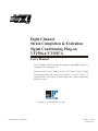
1
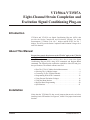
bus
Eight-Channel
Strain Completion & Excitation
Signal Conditioning Plug-on
VT1506A/VT1507A
User’s Manual
The VT1506A/VT1507A manual also applies to Agilent/HP E1413Bs as
Agilent/HP E1413 Options 16/17.
Enclosed is the User’s Manual for the VT1506A/VT1507A Signal
Conditioning Plug-ons. Insert this manual in your VT1413C or
Agilent/HP E1313 or VT1415A manual behind the “Signal Conditioning
Plug-ons” divider.
Copyright © VXI Technology, Inc., 2003
Manual Part Number: 82-0081-000
Printed: July 1, 2003
Printed in U.S.A.
VT1506A/VT1507A
Eight-Channel Strain Completion and
Excitation Signal Conditioning Plug-on
Introduction
VT1506A and VT1507A are Signal Conditioning Plug-ons (SCPs) that
provide the Strain Completion and Excitation Voltages for strain
measurements. VT1506A is for 120 Ω bridges and HP E1507 for 350 Ω
bridges. The SCPs provide Strain Completion and Excitation Voltages for a
total of 8 channels.
About This Manual
Except where noted, all references to the VT1413C apply to the VT1415A
and Agilent/HP E1313. This manual shows how to connect to the Terminal
Module for strain measurements and also shows how to control the Signal
Conditioning Plug-on (SCP) using SCPI commands and Register-Based
commands. The following also explains the capabilities of the SCP and gives
the specifications. The manual contents consist of:
•
•
•
•
•
•
•
•
How The VT1413C Makes Strain Measurements . . . . . . . . . . . . . . 2
Selecting The 1/4 Bridge Jumper . . . . . . . . . . . . . . . . . . . . . . . . . . . 4
Connecting To The Terminal Module . . . . . . . . . . . . . . . . . . . . . . . 5
Programming With SCPI Commands. . . . . . . . . . . . . . . . . . . . . . . 12
Using External Excitation Voltages . . . . . . . . . . . . . . . . . . . . . . . . 16
Using the Shunt Resistor . . . . . . . . . . . . . . . . . . . . . . . . . . . . . . . . 18
Register-Based Programming . . . . . . . . . . . . . . . . . . . . . . . . . . . . . 20
Specifications . . . . . . . . . . . . . . . . . . . . . . . . . . . . . . . . . . . . . . . . . 21
Installation
Notice that the VT1506A/07A has several jumpers that must be set before
installing it in its VXI module. See Figures 4, 14 and 15 for jumper location and
function.
Introduction
VT1506A/07A Strain SCP 1
How The VT1413C Makes Strain Measurements
The VT1413C requires two SCPs to make strain gage measurements. One SCP
provides the Excitation Signals and Bridge Connections (i.e., the
VT1506A/07A SCP) and the other SCP, the sense SCP, makes the
measurement connections to the VT1413C (e.g., VT1501A, Direct Input
SCP).
Figures 1, 2 and 3 show examples of a typical 1/4 Bridge, 1/2 Bridge and
Full Bridge strain gage measurement, respectively. In the figures, the Strain
Completion and Excitation SCP supplies the strain completion circuitry for the
1/4 and 1/2 Bridge configurations and the excitation voltage for all the bridge
configurations.
The 1/4 Bridge Jumper must be installed for 1/4 Bridge measurements and
removed for 1/2 and Full Bridge measurements (see “Selecting The 1/4 Bridge
Jumper” on page 4).
The 29.4 kΩ Shunt resistor checks for correct bridge operation by adding it
across one leg of the bridge (see “Using the Shunt Resistor” on page 18).
The Excitation Jumper allows the selection of an internal or external Excitation
Voltage (see “Using External Excitation Voltages” on page 16).
Figure 1. Typical 1/4 Bridge Strain Gage Measurement
2
VT1506A/07A Strain SCP
How The VT1413C Makes Strain Measurements
Figure 2. Typical 1/2 Bridge Strain Gage Measurement
Figure 3. Typical Full Bridge Strain Gage Measurement
How The VT1413C Makes Strain Measurements
VT1506A/07A Strain SCP 3
Selecting The 1/4 Bridge Jumper
Remove the 1/4 Bridge Jumper of any channel that is to make a 1/2 Bridge or a
Full Bridge measurement. Figure 4 shows the location of the jumpers (on the
connector side of the board). The figure shows a removed jumper on channel 7
for a 1/2 or Full Bridge measurement and installed jumpers on channels 0
through 6 for 1/4 Bridge measurements (default setting).
Note
Be sure to keep any removed jumpers for future use, in case 1/4 Bridge
measurements are to be made later.
Figure 4. Location of the 1/4 Bridge Jumper
4
VT1506A/07A Strain SCP
Selecting The 1/4 Bridge Jumper
Connecting To The Terminal Module
This section shows how to make 1/4, 1/2 and Full Bridge strain gage
connections to the Terminal Module. The Terminal Module supplies the
connections between the external strain gages and both the Strain
Completion/Excitation SCP and the sense SCP (e.g., Direct Input SCP).
Connections on the
Terminal Module
The SCP connections for the the Terminal Modules are shown on the stick-on
labels that came with the SCP. Use the appropriate label for the type of
Terminal Module you have. The connections and appropriate stickers for the
different Terminal Modukes are as follows:
• For VT1413C and above Terminal Modules, use stickers for VT1506A/07A
•
•
SCPs. The connections are shown in Figure 5.
For Agilent/HP E1313 Terminal Moduless, use stickers for Agilent/
HP E1506A/07A SCPs. The connections are shown in Figure 6 and 7.
For Agilent/HP E1413B and below Terminal Modules. use stickers for
Agilent/HP E1413 Option 15/16 SCPs. The connections are shown in Figure 8.
Figure 5. VT1506A/07A C-Size Terminal Module Connections
Connecting To The Terminal Module
VT1506A/07A Strain SCP 5
Figure 6 . VT1506A/07A B-Size Terminal Module Connections (Ch. 00 - 31)
Figure 7. VT1506A/07A B-Size Terminal Module Connections (Ch. 32 - 63)
Figure 8. Agilent/HP E1413 Option 16/17 Terminal Module Connections
6
VT1506A/07A Strain SCP
Connecting To The Terminal Module
Typical Location of
Terminal Module
Connections
Figure 9 shows where to connect the strain gages to the Terminal Module. The
figure assumes that the Strain Completion and Excitation SCP is the first SCP
(i.e., SCP 0) and the Direct Input SCP is the second SCP (i.e., SCP 1).
Figure 9. Typical Locations of Terminal Module Connections
Connecting To The Terminal Module
VT1506A/07A Strain SCP 7
Wiring the Terminal
Module
• See “Attaching and Wiring the Terminal Module” in the VT1413C
User’s Manual to wire the strain gages to the Terminal Module.
• For accurate measurements, use a twisted shielded cable for the
strain gage connections. Connect the shield to the specimen and to
the guard (G) terminal on the Terminal Module.
Note
The following figures in this section show the connections using SCP 0 as
the Strain SCP and SCP 1 as the Direct Input SCP. Use the same technique
using other SCPs and other channel numbers.
For example, for a Channel 00 H and L connection on SCP 0, connect to H
and L on Channel 57 for SCP 7.
1/4 Bridge
Connections
Use Figure 10 for 1/4 Bridge connections to the Terminal Module. Install the
1/4 Bridge Jumper(s) for all channels that are to make 1/4 Bridge
measurements, if jumper(s) is removed (see Figure 4).
Figure 10. Typical 1/4 Bridge Connections
8
VT1506A/07A Strain SCP
Connecting To The Terminal Module
1/2 Bridge
Connections
Use Figure 11 for 1/2 Bridge connections to the Terminal Module. Remove the
1/4 Bridge Jumper(s) for all channels that are to make 1/2 Bridge
measurements, if jumper(s) is installed (see Figure 4).
Figure 11. Typical 1/2 Bridge Connections
Connecting To The Terminal Module
VT1506A/07A Strain SCP 9
Full Bridge
Connections
Use Figure 12 and 13 for Full Bridge connections to the Terminal Module.
Remove the 1/4 Bridge Jumper(s) for all channels that are to make Full Bridge
measurements, if jumper(s) is installed (see Figure 4).
Figure 12. Full Bridge Connections
10
VT1506A/07A Strain SCP
Connecting To The Terminal Module
Figure 13. Full Bridge Connections (Cont.)
Connecting To The Terminal Module
VT1506A/07A Strain SCP 11
Programming With SCPI Commands
The following SCPI commands verify the SCP types installed in theVT1413C
and how to program the VT1413C for strain measurements using the
VT1506A/07A SCPs. The commands listed in this section are also shown in
Chapter 5 of the VT1413C User’s Manual.
Configuring the ID
of the SCP
A configuration jumper must be installed when the VT1506A/07A is to be
used in Agilent/HP E1413A/B Scanning A/D modules. This jumper must be
removed when the VT1506A/07A is to be used in VT1413C and
Agilent/HP E1313A Scanning A/D modules or in VT1415A Algorithmic
Controller modules. See Figure 14 for jumper location.
Figure 14. SCP ID Select Jumper
Checking the ID of
the SCP
A f t er c o n f ig u r i n g t h e I D S el e ct j u mp e r , u se t h e
“SYSTem:CTYPe? (@<channel>)” command to verify the SCP type(s) in
the VT1413C.
• The channel parameter specifies a single channel in the channel
range covered by the SCP of interest. The first channel numbers for
each of the eight SCP positions are: 0, 8, 16, 24, 32, 40, 48 and 56.
The value returned for the VT1506A SCP in an Agilent/HP E1413A/B is:
HEWLETT-PACKARD, E1413 Opt 16 120-Ohm Strain Bridge Completion SCP,0,0
12
VT1506A/07A Strain SCP
Programming With SCPI Commands
The value returned for the VT1506A SCP in a VT1413C/VT1415A or an
Agilent/HP E1313A/E1415A is:
HEWLETT-PACKARD, E1506 120-Ohm Strain Bridge Completion SCP,0,0
The value returned for the VT1507A SCP in an Agilent/HP E1413A/B is:
HEWLETT-PACKARD, E1413 Opt 17 350-Ohm Strain Bridge Completion SCP,0,0
The value returned for the VT1507A SCP in a VT1413C/VT1415A or an
Agilnet/HP E1313A is:
HEWLETT-PACKARD, E1507 350-Ohm Strain Bridge Completion SCP,0,0
To determine the type of SCP installed on channels 0 through 7, send:
SYST:CTYP? (@100)
query SCP type @ ch 0
enter statement here
enter response string
Making 1/4 Bridge
Measurements
The following example shows how to make 1/4 Bridge measurements. The example
uses a Strain Completion and Excitation SCP (VT1506A or VT1507A) for the
source and a Direct Input SCP (VT1501A) for the sense. The source channels
(0 through 7) are set for 1/4 Bridge configuration (1/4 Bridge Jumper installed). The
sense channels are 8 through 15.
Bridge is Unstrained
The following specifies the parameters to convert strain gage readings for the
specified sense channels. Do the following when the bridge is in the Unstrained
configuration:
Bridge is Strained
Programming With SCPI Commands
CAL:TARE (@108:115)
measure the unstrained voltage
on sense channels 8-15
CAL:TARE?
to return the success flag from
the CAL:TARE operation
enter CAL:TARE query
wait until success flag from
CAL:TARE operation is returned
STR:GFAC 2,(@108:115)
specifies the gage factor on sense
channels 8-15; selected factor is
2 (default value)
FUNC:STR:QUAR 1,(@108:115)
link channel 8-15 to EU conversion
for strain measurement; selected
voltage range is 1 V
When the bridge is in the Strained configuration and measurement are to be
made, use the VT1413C’s INITiate and TRIGger commands to make the strain
measurements. You must define what triggers, etc., to use to make the
measurements (see the “VT1413C User’s Manual” for information).
VT1506A/07A Strain SCP 13
Making Full
Bending Poisson
Bridge
Measurements
The following example shows how to make Full Bridge Bending Poisson
Bridge measurements. The example uses a Strain Completion and Excitation
SCP (VT1506A or VT1507A) for the source and a Direct Input SCP
(VT1501A) for the sense. The source channels (0 through 7) are set for Full
Bridge configuration (1/4 Bridge Jumper removed). The sense channels are
8 through 15.
Bridge is Unstrained
The following specifies the parameters to convert strain gage readings for the
specified sense channels. Do the following when the bridge is in the
Unstrained configuration:
Bridge is Strained
Comments
How to Link EU
Conversions to
Channels
CAL:TARE (@108:115)
measure the unstrained voltage
on sense channels 8-15
CAL:TARE?
to return the success flag from
the CAL:TARE operation
enter CAL:TARE query
wait until success flag from
CAL:TARE operation is returned
STR:GFAC 2,(@108:115)
specifies the gage factor on sense
channels 8-15; selected factor is
2 (default value)
STR:POIS .3,(@108:115)
set Poisson ratio for EU
conversion; selected value is .3
(default value)
FUNC:STR:FBP 1,(@108:115)
link channel 8-15 to EU
conversion for strain
measurement; selected voltage
range is 1 V
When the bridge is in the Strained configuration and measurement are to be
made, use the VT1413C’s INITiate and TRIGger commands to make the strain
measurements. You must define what triggers, etc., to use to make the
measurements (see the “VT1413C User’s Manual” for information).
The following explains the commands used in strain measurements.
The following explains the commands that link the strain EU conversion with
the specified channels. The commands tell the VT1413C to use the EU
conversion for strain measurements. The VT1413C performs the appropriate
EU conversion (e.g., 1/4 Bridge measurements) depending on the command
used. Thus, each bridge configuration has its own command with the command
used for the 1/4 Bridge configuration as the default value. (See “Linking
Channels with EU Conversion” in Chapter 3 of the VT1413C User’s Manual.)
The syntax of a typical command is:
[SENse:]FUNCtion:STRain:HBENding [<range>,](@<ch_list>)
where <range> is the voltage range of the VT1413C (default value or no
specified parameter is AUTO) and <ch_list> specifies the channels of the sense
14
VT1506A/07A Strain SCP
Programming With SCPI Commands
SCP (e.g., VT1501A, Direct Input) that connects to the bridge (not the Strain
Completion and Excitation SCP).
The different bridge types and corresponding EU to Channels Linking
commands are in the following table.
Bridge Type
Full Bending Bridge
Full Bending Poisson Bridge
Full Poisson Bridge
1/2 Bending Bridge
1/2 Poisson Bridge
1/4 Bridge
Purpose of Channel
Tare Calibration
(CAL:TARE)
Command
[SENse:]FUNCtion:STRain:FBENding
[SENse:]FUNCtion:STRain:FBPoisson
[SENse:]FUNCtion:STRain:FPOisson
[SENse:]FUNCtion:STRain:HBENding
[SENse:]FUNCtion:STRain:HPOisson
[SENse:]FUNCtion:STRain[:QUARter]
The CALibration:TARE command measures the voltage across the bridge to
determine the unstrained voltage value of the bridge. This corrects for the
offset voltage across the bridge when in the Unstrained configuration.
The command automatically executes the CAL? command and thus calibrates
the internal excitation supply of the Bridge Completion and Excitation SCP.
The VT1413C uses the unstrained reading (i.e., offset voltage) in conjunction
with the strain gage factor (see “Purpose of the Strain Gage Factor Command
(STR:GFAC)” below) to calculate the strain measurements. You normally
perform both operations before making the actual strain measurements.
Instead of using CAL:TARE, you can use the [SENSe:]STRain:UNSTrained
command to enter the unstrained voltage. In this case you must measure and
enter the offset voltage of the bridge, when the bridge is Unstrained. The
command syntax is:
[SENSe:]STRain:UNSTrained <unstrained_v>,(@<ch_list>)
where <unstrained_v> is the voltage value of the bridge in the unstrained
position (default is 0 V) and <ch_list> specifies the channels of the sense SCP
(e.g., VT1501A, Direct Input) that connects to the bridge (not the Strain
Completion and Excitation SCP).
Purpose of the Strain
Gage Factor Command
(STR:GFAC)
The [SENse:]STRain:GFACtor command specifies the gage factor to be used
by the VT1413C to calculate the strain measurements. The default value of the
command is a factor of 2. The command syntax is:
[SENse:]STRain:GFACtor <gage_factor>,(@<ch_list>)
Programming With SCPI Commands
VT1506A/07A Strain SCP 15
where <gage_factor> is the gage factor value (default is 2) and <ch_list>
specifies the channels of the sense SCP (e.g., VT1501A, Direct Input) that
connects to the bridge (not the Strain Completion and Excitation SCP).
Purpose of the Poisson
Ratio Command
(STR:POIS)
The [SENse:]STRain:POISson command sets the Poisson ratio to be used
by the VT1413C for EU conversion of strain values measured (see “Linking
Channels with EU Conversion” in Chapter 3 of the VT1413C User’s Manual).
This command is only needed if making Poisson strain measurements. It is not
needed for making 1/4 Bridge or 1/2 or Full Bridge Bending measurements.
The default value of the command is 0.3. The command syntax is:
[SENse:]STRain:POISson <poisson_ratio>,(@<ch_list>)
where <poisson_ratio> is the Poisson ratio (default is 2) and <ch_list> specifies
the channels of the sense SCP (e.g., VT1501A, Direct Input) that connects to the
bridge (not the Strain Completion and Excitation SCP).
NOTE
Because of the number of possible strain gage configurations, the driver must
generate any Strain EU conversion tables and download them to the instrument
when INITiate is executed. This can cause the time to complete the INIT
command to exceed 1 minute.
Using External Excitation Voltages
You can use your own external excitation voltage instead of using the internal
voltage of the Bridge Completion and Excitation SCP. If using an external
voltage, you must:
• isolate the internal excitation supply that is on the SCP
• connect the external voltage to the Terminal Module
• enter the value of the excitation voltage into the VT1413C so it can
make the correct EU conversions for strain measurements
Isolating the
Internal Excitation
Supply
16
VT1506A/07A Strain SCP
To use an external excitation voltage, isolate the internal excitation supply
from the bridge. To do this, remove the “Excitation Jumpers” from the Bridge
Completion and Excitation SCP as shown in Figure 15.
Using External Excitation Voltages
Figure 15. Isolating the Internal Excitation Supply
Connecting the
External Supply
Note
Enter Excitation
Voltage Value
Use Figure 16 to connect to external supply to the Terminal Module. Be sure
the “Excitation Jumper” is removed from the Strain Completion and Excitation
SCP before connecting the external supply (see “Isolating the Internal
Excitation Supply” above).
Be sure to keep the removed jumper for future use, in case the internal
Excitation Supply is to be used later.
Use the [SENSe:]STRain:EXCitation command to enter the value of the
external excitation voltage. The syntax of the command is:
[SENSe:]STRain:EXCitation <excite_v>,(@<ch_list>)
where <excite_v> is the value of the external excitation voltage and <ch_list>
specifies the channels of the sense SCP (e.g., VT1501A, Direct Input) that
connects to the bridge (not the Strain Completion and Excitation SCP).
The default value of the excitation voltage is 3.9 V, which is also the value of
the internal excitation supply. The minimum allowable voltage value that can
be entered is 0.01 V and the maximum value is 42 V.
Using External Excitation Voltages
VT1506A/07A Strain SCP 17
Completion/Excitation SCP
Sample
Shield
External Excitation
Connect the External Excitation Supply to any "+" and "-" terminal pair.
Shown is a 1/4 Bridge configuration; connections to other configurations is the same.
Figure 16. Connecting the External Excitation Supply
Using The Shunt Resistor
To check if the bridge is operational, you can add a 29.4 kΩ Shunt resistor
across one leg of the bridge, as illustrated in Figure 17. A FET switch adds or
removes the resistor. When the resistor is added, it changes the unstrained
offset voltage on the bridge.
The resistor can only affect the bridge balance as long as you follow the
connections shown in Figures 1, 2 and 3. Use the OUTPut:SHUNt command
to add or remove the resistor from the bridge. The syntax of the command is:
OUTPut:SHUNt 1 | 0 | ON | OFF
18
VT1506A/07A Strain SCP
Using The Shunt Resistor
where 1 or ON adds the shunt resistor and 0 or OFF (default value) removes the
resistor.
Figure 17. Adding the Shunt Resistor
Using The Shunt Resistor
VT1506A/07A Strain SCP 19
Register-Based Programming
Chapter 6 of the VT1413C User’s Manual cover the Register-Based
commands shown below. You should read that chapter to become familiar
with accessing registers and executing Register-Based commands. This
section relates those commands to the parameter values that are specified for
this SCP.
When Register Programming an SCP, most communication is through the
Signal Conditioning Bus. For that you will use the Register Commands:
SCPWRITE <regaddr> <regvalue>
and
SCPREAD? <regaddr>
Read (returned value)
Write (<regvalue>)
SCP Register
SCP ID - Opt 16: (C0C016)
- Opt 17: (C04016)
- VT1506A: (C0B016)
- VT1507A: (C03016)
00ppp0000002
SCP Gain Scale (XXX016)
SCP Excitation
Activation (XXX116)
Channel Gain (XXX016)
Whole SCP Reg 1
00ppp0000012
Whole SCP Reg 2
00ppp0000022
Channel Reg 1
01pppccc0012
Calibration (Xnnn16) Whole SCP Reg 3
where nnn = Cal Value
XXX = Don't Care
<regaddr> Value
01ppp0000032
ppp = Plug-on
ccc = SCP channel
Checking the ID of
the SCP
To query an SCP for its ID value, write the following value to Parameter
Register 0:
( SCP number ) × 4016
Then write the opcode for SCPREAD? (080016) to the Command Register. The
ID value will be written to the Response Register. Read the Response Register
for the value.
Excitation
Voltage Activation
(VT1506A/07A Only)
After the VT1506A/07A is reset or after a power-on condition, the SCP’s
excitation voltage is not enabled. (This is only for the VT1506A/07A and not
the Agilent/HP E1413 Options 16/17.) To enable the excitation voltage, write
a 1 to Register 2.
Excitation
Calibration Register
The excitation calibration register controls a DAC that adjusts the SCP’s
internal excitation voltage for 3.9 V. The Register-Based command
CARDCAL? (100016) controls this register and the user should not write to
them.
20
VT1506A/07A Strain SCP
Register-Based Programming
Specifications
General
Specification
SCP Current Requirements:(Amps)
E1506A
E1507A
5 VTYP
0.28
0.09
5 Vmax
0.28
0.09
24 VTYP
0.026
0.026
24 VMAX -24 Vtyp -24 VMAX
0.032
0.023
0.027
0.032
0.023
0.027
Excitation Voltage (measured with VT1501A, Direct Input)
Accuracy: (90 day) 23°C, ±1°C with *CAL done after 1 hr. warmup
3.9000 V nominal ±512 µV
Noise: (3 sigma) (350 Ω completion, one channel, 3.90 V)
A/D Filter Off: 450 µV
A/D Filter On: 366 µV
Tempco: 39 µV/°C (difference between factory calibration and
*CAL temp)
Completion Resistors
Power:
0.125 W @125°C
Tolerance: 0.05%
TCR:
±5 ppm/°C
Bridge Offsets: (±1°C of tare cal, 1/4 Bridge)
Offset: ±40 µV Note: Offset may vary depending on the stability of the
attached strain gage
Strain Accuracies for System
Gain + Offset Error: 40 µe
Noise Error: 27 µe - A/D Filter Off
20 µe - A/D Filter On
Strain Measurement
Accuracies
Specifications
The graphs on the following pages shows the following strain accuracies:
•
•
•
•
•
•
Quarter Bridge (1/4 Bridge )
Half Bridge (1/2 Bridge) Bending
Half Bridge (1/2 Bridge) Poisson
Full Bridge Bending
Full Bridge Poisson
Full Bridge Bending Poisson
VT1506A/07A Strain SCP 21
22
VT1506A/07A Strain SCP
Specifications
Specifications
VT1506A/07A Strain SCP 23
24
VT1506A/07A Strain SCP
Specifications
Specifications
VT1506A/07A Strain SCP 25
26
VT1506A/07A Strain SCP
Specifications
Specifications
VT1506A/07A Strain SCP 27