1
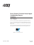
HP 75000 SERIES B and C
Eight-Channel Direct Input
Signal Conditioning Plug-on
HP E1501
User’s Manual
The HP E1501 manual also applies to HP E1413Bs as HP E1413 Option 11.
Enclosed is the User’s Manual for the HP E1501 (HP E1413 Option 11 for HP
E1413Bs) Signal Conditioning Plug-on. Insert this manual in your HP E1413/E1313
manual behind the “Signal Conditioning Plug-ons” divider.
Copyright © Hewlett-Packard Company, 1993, 1994, 1995, 1996
*E1501-90001*
E1501-90001
Manual Part Number:
E1501-90001
Printed: JANUARY 1996 Edition 1
Printed in U.S.A. E 0196
HP E1501
Eight-Channel Direct Input
Signal Conditioning Plug-on
Introduction
The HP E1501 is the most basic Signal Conditioning Plug-on. The Direct
Input SCP provides 8 hard wired paths that do not modify the input signal at
all. The SCP provides input over-voltage detection and open transducer
detection on each channel.
About this Manual
This manual shows you how to control the Signal Conditioning Plug-on
(SCP) using SCPI commands as well as Register-Based commands, and
explains the capabilities of this SCP. The contents of this manual are:
•
•
•
•
•
•
•
Installation . . . . . . . . . . . . . . . . . . . . . . . . . . . . . . . . . . . . . . .
Field Wiring . . . . . . . . . . . . . . . . . . . . . . . . . . . . . . . . . . . . .
Connecting To The Terminal Module . . . . . . . . . . . . . . . . . .
Identifying the Plug-on . . . . . . . . . . . . . . . . . . . . . . . . . . . . .
Programming With SCPI Commands . . . . . . . . . . . . . . . . . .
Programming With Register Commands . . . . . . . . . . . . . . .
Specifications . . . . . . . . . . . . . . . . . . . . . . . . . . . . . . . . . . . .
3
3
4
6
6
9
11
Installation
Installation for this Plug-on is common to several others and is covered in
Chapter 1 of your HP E1413/E1313 manual.
Field Wiring
Although field wiring is covered in Chapter 2 of your HP E1413/E1313
manual, a special consideration for the Direct Input SCP is that a channel
input pair must have a return path to guard or ground. NanoAmp currents
sourced from the HP E1413’s A/D could cause inputs left floating (or
isolated) to exceed the input protection trip point. When using isolated
thermocouples, connect the shield to thermocouple low as close to the
thermocouple junction as possible. The other end of the shield should be
Introduction
HP E1501 Direct Input SCP
3
connected to guard or ground. See “ Preferred Signal Connections” in the
main manual.
Connecting To The Terminal Module
This section shows how to make connections to the Terminal Module.
The SCP connections for the Terminal Modules are shown on the stick-on
labels that came with the SCP. Use the appropriate label for the type of
Terminal Module you have. The connections and appropriate stickers are as
follows:
• For HP E1413C and above Terminal Modules, use stickers for
HP E1501 SCPs. The connections are shown in Figure 1.
• For HP E1313 Terminal Moduless, use stickers for HP E1501 SCPs.
The connections are shown in Figures 2 and 3.
• For HP E1413B and below Terminal Modules, use stickers for
HP E1413 Option 11 SCPs. The connections are shown in Figure 4.
Figure 1 HP E1501 C-Size Terminal Module Connections
4
HP E1501 Direct Input SCP
Connecting To The Terminal Module
Figure 2 HP E1501 B-size Terminal Module Connections (Ch 00-31)
Figure 3 HP E1501 B-size Terminal Module Connections (Ch 32-63)
Figure 4 HP E1413 Option 11 Terminal Module Connections
Connecting To The Terminal Module
HP E1501 Direct Input SCP
5
Identifying the Plug-on
You’ll find the HP part number on the connector side of the SCP to the left
of the serial number bar code. For the HP E1501, the part number is :
E1413-63511
Programming With SCPI Commands
The SCPI commands shown here are covered in Chapters 3 and 5 of your
HP E1413/E1313 manual. This section will relate those commands to the
parameter values which are specific to this Plug-on.
Checking the ID
of the SCP
To verify the SCP type(s) installed on the HP E1413/E1313 use the
SYSTem:CTYPe? (@<channel>) command.
• The channel parameter specifies a single channel in the channel
range covered by the SCP of interest. The first channel number for
each of the eight SCP positions are; 0,8,16,24,32,40,48, and 56.
The value returned for the SCP in an HP E1413B is:
HEWLETT-PACKARD,E1413 Opt 11 8-Channel Straight-Through SCP,0,0
The value returned for the SCP in an HP E1413C/E1313A is:
HEWLETT-PACKARD,E1501 8-Channel Straight-Through SCP,0,0
To determine the type of SCP installed on channels 0 through 7 send
Querying the Filter
Cutoff Frequency
SYST:CTYP? (@100)
query SCP type @ ch 0
enter statement here
enter response string
While the Direct Input SCP does not provide any filtering, the cutoff
frequency can be queried. Response to this query will always be 0 (zero).
To query any channel for its cutoff frequency use the
INPut:FILTer[:LPASs]:FREQuency? (@<channel>) command. The
INP:FILT:FREQ? command returns the numeric cutoff value currently set
for the channel specified.
• The channel parameter must specify a single channel.
6
HP E1501 Direct Input SCP
Identifying the Plug-on
To query the cutoff frequency of channel 6 send
INP:FILT:FREQ? (@106)
query channel 6
enter statement here
Querying the
Filter State
While the Direct Input SCP does not provide any filtering, the state of the
filter can be queried. Response to this query will always be 0 (zero). To
query any channel to determine if it is enabled or disabled use the
INPut:FILTer[:LPASs][:STATe]? (@<channel>) command. The
INP:FILT? command returns a 0 if the channel is OFF or a 1 if the channel
is ON.
• The channel parameter must specify a single channel.
To query the filter state of channel 2 send
INP:FILT? (@102)
query channel 2
enter statement here
Querying the
Channel Gain
While the Direct Input SCP does not provide amplifiers, the channel gain
can be queried. Response to this query will always be 1. To query any
channel to determine its gain setting use the INPut:GAIN? (@<channel>)
command. The INP:GAIN? command returns the current gain value for the
specified channel.
• The channel parameter must specify a single channel.
To query the gain setting of channel 8 send
INP:GAIN? (@108)
query channel 8
enter statement here
Detecting Open
Transducers
This SCP provides a method to detect open transducers. When Open
Transducer Detect (OTD) is enabled, the SCP injects a small current into
the HIGH and LOW input of each channel. The polarity of the current pulls
the HIGH inputs toward +17 volts and the LOW inputs towards -17 volts. If
a transducer is open, measuring that channel will return an over-voltage
condition. OTD is available on a per SCP basic. all eight channels of an
SCP are enabled or disabled together. See Figure 8 for a simplified
schematic diagram of the OTD circuit.
Programming With SCPI Commands
HP E1501 Direct Input SCP
7
NOTE
When OTD is enabled, the inputs have up to 0.2µA injected into them. If
this current will adversely affect your measurement, but you still want to
check for open transducers, you can enable OTD, make a single scan, check
the CVT for bad measurements, then disable OTD and make your regular
measurement scans. The specifications apply only when OTD is off.
To enable or disable Open Transducer Detection, use the
DIAGnostic:OTDetect <enable>, (@<ch_list>) command.
• The enable parameter can specify ON or OFF
• An SCP is addressed when the ch_list parameter specifies a channel
number contained on the SCP. The first channel on each SCP is:
0, 8, 16, 24, 32, 40, 48, and 56
To enable Open Transducer Detection on all channels on SCPs 1 and 3:
DIAG:OTD ON, (@100,116)
0 is on SCP 1 and 16 is on SCP3
To disable Open Transducer Detection on all channels on SCPs 1 and 3:
DIAG:OTD OFF, (@100,116)
Signal Input
Signal Conditioning Plug-on
High
Multiplexer
High
+17V
100M
3K
Gnd.
3K
100M
-17V
Low
Low
Figure 5 Open Transducer Detect Circuit
8
HP E1501 Direct Input SCP
Programming With SCPI Commands
Register Based Programming
The register-based commands shown here are covered in Appendix D of the
HP E1413/E1313 manual. You should read that section first to become
familiar with accessing registers and executing Register-Based Commands.
This section will relate those commands to the parameter values which are
specific to this Plug-on.
When Register Programming an SCP most communication is through the
Signal Conditioning Bus. For that you will use the Register Commands:
SCBWRITE <regaddr> <regvalue>
and
SCBREAD? <regaddr>
HP E1501 Register Map
Write( <regvalue>)
Read (returned value)
SCP ID (202016)
SCP Register
Whole SCP Reg 0
<regaddr> Value
00ppp0000002
ppp=Plug-on
ccc=SCP channel
In addition you will access bits in the Card Control register to control Open
Transducer Detection.
Checking ID of SCP
To query an SCP for its ID value, write the following value to Parameter
Register 1:
(SCP number) × 4016
Then write the opcode for SCBREAD? (080016) to the Command Register.
The ID value will be written to the Query Response Register.
Detecting Open
Transducers
Open Transducer Detection (OTD) is controlled by bits in the Card Control
Register. For more information on OTD see Figure 1.
Card Control Register
15
14
PSI Pwr Reset FIFO Mode
(Base + 1216)
14-13
12
11
10-8
7-0
unused
FIFO Clear
VPPEN
A24 Window
Open Transducer Detect
Writing a one (1) to a bit enables open transducer detect on that signal
conditioning module. Writing a zero (0) to a bit disables open transducer
detect. See following table.
Register Based Programming
HP E1501 Direct Input SCP
9
10
Bit 7
Bit 6
Bit 5
Bit 4
Bit 3
Bit 2
Bit 1
Bit 0
SCP 7
SCP 6
SCP 5
SCP 4
SCP 3
SCP 2
SCP 1
SCP 0
HP E1501 Direct Input SCP
Register Based Programming
Specifications
These specifications for the HP E1501 reflect the combined performance of
the HP E1413/E1313 and the Direct Input Signal Conditioning Plug-on.
These specifications are not to be added to those presented in the
HP E1413/E1313 User’s Manual.
General Specifications
Measurement ranges
DC Volts
(Opt 11) ±62.5mV to ±16V Full Scale
Temperature
Thermocouples - -200 to +1700 °C
Thermistors - (Opt 15 required) -80 to +160 °C
RTD’s - (Opt 15 required) -200 to +850 °C
Resistance
(Opt 15 with opt 11) 512 ohms to 131 Kohms FS
Strain
25,000 µe or limit of linear range of strain gage
Maximum input voltage
Operating: < ±16 V peak
Damage level: > ±42 V peak
Operating: < ±16 V peak
Damage level: > ±42 V peak
(Normal mode plus common mode)
Maximum common mode
voltage
0 to 60Hz -105dB
Common mode rejection
greater than 100 Mohm differential
Input impedance
Maximum tare cal offset
Specifications
(Maximum tare offset depends on A/D range and SCP gain)
A/D range
±V F.Scale
16
4
1
0.25
0.0625
Max Offset
3.2213
.82101
.23061
.07581
.03792
HP E1501 Direct Input SCP
11
(90 days) 23°C ±1°C (with *CAL? done after 1 hr warm up and CAL:ZERO?
within 5 min.). If autoranging is ON, add ±.02% FS to accuracy specifications.
For E1313, multiply Noise Spec. by 1.4.
Measurement accuracy
DC Volts
A/D range
±V F.Scale
Linearity
% of reading
Offset Error
Noise
3 sigma
Noise*
3 sigma
.0625
.25
1
4
16
0.01%
0.01%
0.01%
0.01%
0.01%
5.3 µV
10.3 µV
31 µV
122 µV
488 µV
18 µV
45 µV
110 µV
450 µV
1.8 mV
8 µV
24 µV
90 µV
366 µV
1.5 mV
* [SENSe:]FILTer[:LPASs][:STATe] ON (max scan rate - 100 rdgs/sec/channel)
Temperature Coefficients: Gain - 10ppm/°C. Offset - (0 - 40°C) .14µV/°C, (40 - 55°C) .8µV+.38µV/°C
Measurement accuracy
Temperature
(90 days) 23°C ±1°C (with *CAL? done after 1 hr warm up and CAL:ZERO? within 5
min.). If autoranging is ON, add ±.02% FS to accuracy specifications.
(simplified specifications, see
temperature accuracy graphs in HP
E1413/E1313 manual for details)
The temperature accuracy specifications include instrument and firmware
linearization errors. The linearization algorithm used is based on the IPTS-68(78)
standard transducer curves. Add your transducer accuracy to determine total
measurement error.
Thermocouples
Type E
Type EEXtended
Type J
Type K
Type R
A/D Filter
-200 to 0 °C
0 to 200 °C
200 to 400 °C
400 to 800 °C
OFF
ON*
2.25°C
1.65°C
0.37°C
0.22°C
0.27°C
0.15°C
0.25°C
0.15°C
A/D Filter
-200 to 0 °C
0 to 200 °C
200 to 800 °C
800 to 1000 °C
OFF
ON*
13.3°C
12.7°C
0.70°C
0.40°C
0.30°C
0.20°C
0.60°C
0.30°C
A/D Filter
-200 to 0 °C
0 to 200 °C
200 to 600 °C
600 to 775 °C
OFF
ON*
2.10°C
1.75°C
0.45°C
0.25°C
0.35°C
0.20°C
0.35°C
0.20°C
A/D Filter
-200 to 0 °C
0 to 400 °C
400 to 800 °C
800 to 1400°C
OFF
ON*
3.50°C
3.10°C
0.60°C
0.30°C
0.50°C
0.25°C
0.60°C
0.35°C
A/D Filter
0 to 100 °C
100 to 200 °C
200 to 600 °C
600 to 1000 °C
OFF
ON*
4.25°C
2.60°C
2.75°C
1.65°C
2.25°C
1.20°C
1.70°C
0.90°C
* [SENSe:]FILTer[:LPASs][:STATe] ON (max scan rate - 100 rdgs/sec/channel)
(simplified specifications, see temperature accuracy graphs in HP E1413/E1313
manual for details)
Measurement accuracy
Temperature (cont.)
Thermocouples (cont.)
Type S
12
A/D Filter
HP E1501 Direct Input SCP
0 to 100 °C
100 to 200 °C
200 to 800 °C
800 to 1750 °C
Specifications
Type T
OFF
ON*
5.50°C
4.00°C
3.50°C
2.30°C
2.50°C
1.50°C
1.80°C
0.90°C
A/D Filter
-200 to -100°C
-100 to 0 °C
0 to 200 °C
200 to 400 °C
OFF
ON*
2.38°C
1.78°C
0.80°C
0.50°C
0.55°C
0.30°C
0.38°C
0.20°C
5KΩ Reference Thermistor
A/D Filter
-10 to 65 °C
65 to 85 °C
OFF
ON*
0.012°C
0.0095°C
0.016°C
0.0100°C
A/D Filter
-125 to 75°C
OFF
ON*
0.40°C
0.21°C
A/D Filter
-200 to 75 °C
75 to 300 °C
300 to 600 °C
600 to 970 °C
OFF
ON*
0.12°C
0.07°C
0.28°C
0.18°C
0.35°C
0.25°C
0.45°C
0.36°C
A/D Filter
0 to 30 °C
30 to 70 °C
70 to 80 °C
80 to 100 °C
OFF
ON*
0.012°C
0.010°C
0.013°C
0.012°C
0.012°C
0.008°C
0.019°C
0.013°C
A/D Filter
0 to 30 °C
30 to 70 °C
70 to 85 °C
OFF
ON*
0.014°C
0.011°C
0.020°C
0.014°C
0.028°C
0.019°C
A/D Filter
0 to 30 °C
30 to 60 °C
60 to 90 °C
90 to 115 °C
OFF
ON*
0.015°C
0.013°C
0.020°C
0.014°C
0.023°C
0.017°C
0.035°C
0.023°C
100Ω Reference RTD
100Ω RTD
2252Ω Thermistor
5KΩ Thermistor
10KΩ Thermistor
Notes
Specifications
HP E1501 Direct Input SCP
13