1
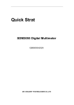
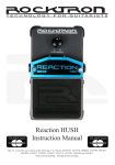
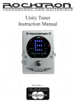
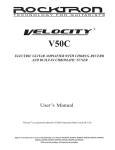
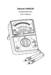
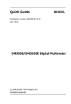
V15
ELECTRIC GUITAR AMPLIFIER
User’s Manual
Velocity R is a registered trademark of GHS Corporation Battle Creek MI, USA
May be covered by one or more of the following: U.S. Patents #4538297, 4647876, 4696044, 4745309, 4881047, 4893099,
5124657, 5263091, 5268527, 5319713, 5333201, 5402498 and 5493617.
Other patents pending. Foreign patents pending.
Your Rocktron Velocity V15 amplifier has been designed to comply with the following Standards
and Directives as set forth by the European Union:
Council Directive(s):
89/336/EEC, 73/23/EEC, 76/769/EC, 1994/62/EC, 2000/
53/EC, 2002/95/EC
Standard(s):
EN55022, EN50082-1, EN60065
This means that this product has been designed to meet stringent guidelines on how much RF
energy it can emit, and that it should be immune from other sources of interference when properly
used. Improper use of this equipment could result in increased RF emissions, which may or may not
interfere with other electronic products.
To insure against this possibility, always use good shielded cables for all audio input connections.
This will help insure compliance with the Directive(s).
V15 Specifications
Power Output
15 Watts
Speakers
1 x 6.5” Custom Voiced Velocity Speakers by Rocktron
EQ
Bass
Middle
Treble
Presence
Headphone Output
One 1/4” jack
Channels
DISTORTION and CLEAN (Footswitchable via Rocktron
RFS1 footswitch - sold separately)
Dimensions
295mm(W) x 350mm(H) x 172mm(D)
11.5” x 14” x 7”
Weight
15lbs (6.8KG)
Power Requirements
100 Volts AC 50/60Hz or 117 Volts AC, 50/60Hz
or 220/240 Volts AC, 50/60Hz, as specified on chassis
Fuse
100-120V - use F500mA
220-240V - use F300mA
Copyright © 2006 GHS Corporation
All Rights Reserved.
Precautions
NOTE: IT IS VERY IMPORTANT THAT YOU READ THIS SECTION TO PROVIDE
YEARS OF TROUBLE FREE USE. THIS UNIT REQUIRES CAREFUL HANDLING.
• All warnings on this equipment and in the operating instructions should be
adhered to and all operating instructions should be followed.
• Do not use this equipment near water. Care should be taken so that
objects do not fall and liquids are not spilled into the unit through any
openings.
• The power cord should be unplugged from the outlet when left unused for
a long period of time.
• Do not block any ventilation openings (if applicable). Install in accordance
with the manufacturer’s instructions.
• Do not install near any heat sources such as radiators, heat registers, stoves
or other apparatus (including amplifiers) that produce heat.
• Only used attachments/accessories specified by the manufacturer.
• Do not use this product with any case, stand tripod, bracket or table that is
not specified by the manufacturer. Insure that the case, stand, tripod,
bracket etc. is properly adjusted and setup (follow all instructions). Extra
care and caution should be taken to avoid tip over and injury.
• Unplug this apparatus during lightning storms or when unused during long
periods of time.
Refer all service to qualified service personnel. Servicing is required when the apparatus has been
damaged in any way, such as power supply or plug is damaged, liquid has been spilled or objects have
fallen into the apparatus or if the apparatus has been exposed to rain or moisture, does not operate
normally or has been dropped.
DO NOT ATTEMPT TO SERVICE THIS EQUIPMENT. THIS EQUIPMENT
SHOULD BE SERVICED BY QUALIFIED PERSONNEL ONLY. DO NOT MAKE
ANY INTERNAL ADJUSTMENTS OR ADDITIONS TO THIS EQUIPMENT AT
ANY TIME. DO NOT TAMPER WITH INTERNAL ELECTRONIC
COMPONENTS AT ANY TIME. FAILURE TO FOLLOW THESE INSTRUCTIONS
MAY VOID THE WARRANTY OF THIS EQUIPMENT, AS WELL AS CAUSING
SHOCK HAZARD.
OPERATING TEMPERATURE
Do not expose this unit to excessive heat. This unit is designed to operate between 32° F
and 104° F (0° C and 40° C). This unit may not function properly under extreme
temperatures.
FRONT PANEL DESCRIPTIONS
1
INPUT jack
Connect the output of your guitar to the 1/4” input jack with a shielded guitar cable.
DISTORTION CHANNEL
2
GAIN control
This knob determines the amount of GAIN (or distortion) added to the signal in the distortion channel.
Turning the knob clockwise will add more GAIN to the signal. Turning the knob counter-clockwise will
decrease the amount of GAIN added to the signal.
3
LEVEL control
This knob determines the LEVEL (or volume) of the distortion channel. Turning the knob clockwise will
increase the LEVEL of the distortion channel. Turning the knob counter-clockwise will decrease the
LEVEL of the distortion channel.
4
CH SELECT Button & LED
Channel Select button allows you to select between the DISTORTION or the CLEAN channel. When the
Channel Select LED is ON (or lit) the DISTORTION channel is active. When the Channel Select LED is
OFF (dark) the CLEAN channel is active.
CLEAN CHANNEL
5
LEVEL control
This knob determines the LEVEL (or volume) of the CLEAN channel. Turning the knob clockwise will
increase the LEVEL of the clean channel. Turning the knob counter-clockwise will decrease the LEVEL of
the clean channel.
EQUALIZATION CONTROLS
6
BASS control
This knob controls the overall bass of both the DISTORTION and CLEAN channels. The BASS control
boosts or cuts the amount of low frequency, or bass sound in the signal.
7
MIDDLE control
This knob controls the overall MIDDLE frequencies of both the DISTORTION and CLEAN channels.
The MIDDLE control boosts or cuts the amount of mid-band frequencies present in the signal.
8
TREBLE control
This knob controls the overall TREBLE of both the CLEAN and DISTORTION channels. The TREBLE
control boosts or cuts the amount of high frequencies present in the signal.
9
PRESENCE control
This knob controls the overall PRESENCE of both the CLEAN and DISTORTION channels. The PRESENCE will increase or decrease the definition of the notes being played.
10
HEADPHONE jack
Plugging your headphones into this jack disconnects the sound going to the speakers and allows you
to practice in private.
11
POWER switch
Turns the amp ON and OFF. When the LED is lit, the amp is on.
BACK PANEL DESCRIPTIONS
12
POWER CORD PLUG
Using the supplied detachable power cord, plug the amplifier into any standard wall outlet. Please be sure
to check your local wiring and voltage to make sure your amplifier is the proper voltage for your area of the
world. Please follow all the precaution guidelines found in the front of this manual. When replacing the fuse,
please be sure to replace the fuse with the specific fuse as stated on the chassis next to the power cord plug.
A description on how to change the fuse is covered later in this manual.
FOOTSWITCH Jack
13
FOOTSWITCH Input - RFS1
Using a ROCKTRON RFS1 footswitch (sold separately) you can change the channels between DISTORTION and CLEAN.
* Rocktron single (RFS1) and double (RFS2) footswitches are available and sold separately.
Fuse Replacement
We recommend that you use an authorized repair person to change the fuse in this unit.
To access the fuse, first power down the unit and unplug the cable from the wall outlet and the amplifier.
Using a small screw driver, open the fuse tray by prying open the small tab as shown in the drawing above.
Please note that the tray will not come all of the way out.
Remove the old fuse and replace with a comparable new fuse and close the tray being sure that the tray snaps
into position. You will find the information on the fuse used in the specifications section of this manual.
V15
ELECTRIC GUITAR AMPLIFIER
Rocktron -A Division of GHS Corporation
2813 Wilber Avenue
Battle Creek MI 49015
USA
Rocktron Phone: 1-(269)-968-3351
Email:
[email protected]
Check us out on the web at:
www.rocktron.com
2006-0001
Rev. 8/01/06