1
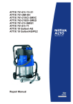
Buddy 15/18
Aero 20-01/INOX
Aero 20-11/-21/-21INOX
Aero 25-11/-21
Service Manual
A. Preface / Safety Instructions
Index
B. Technical data
C. Troubleshooting
D. Service
E. Tools
F. Wiring
Nilfisk
ALTO
Contents
A
Preface / Safety Instructions
.......................................................................... 4
B
Technical data
.......................................................................... 5
C
Troubleshooting
1
2
3
D
Service
Buddy 15/18, Aero 20/25-01/11
- Motor not working........................................... 8
Aero 20/25-21
- Motor not working with switch set to “I”........... 9
Aero 20/25-21/-21INOX
- Motor not working with switch set to “II”.......... 10
1 Suction head (Buddy)..................................... 11
1.1 Disassembling / assembling the intake fitting....11
1.2 Disassembling / assembling the cover.............. 11
2 Container (Aero).............................................. 12
2.1 Disassembling / assembling the container ring
( Aero 20 Inox only)........................................... 12
2.2 Disassembling / assembling the intake fitting
(Aero 20 Inox only)............................................ 12
2.3 Disassembling / assembling the intake fitting in
the plastic container...........................................13
3
3.1
3.2
3.3
3.4
3.5
Suction head / electrical components (Aero)14
Disassembling / assembling the cover.............. 14
Disassembling / assembling the locking clamp 14
Disassembling / assembling the power cord.... 15
Disassembling / assembling the switch.............16
Disassembling / assembling the socket
(Aero 20/25-11/21 only).....................................16
3.6 Disassembling / assembling the start-up unit... 17
3.7 Disassembling / assembling the clamping plate17
3.8 Disassembling / assembling the motor..............18
4 Filter cleaning (Aero)..................................... 19
4.1 Disassembling / assembling filter cleaning
(tappet).............................................................. 19
4.2 Disassembling / assembling filter cleaning
(flap).................................................................. 19
E
Tools
1
F
Wiring
1 Wiring diagram................................................ 21
1.1 Wiring diagram Buddy 15/18,
Aero 20/25-01/INOX..........................................21
1.2 Wiring diagram Aero 20/25-11.......................... 22
1.3 Wiring diagram Aero 20/25-21/-21INOX............23
Buddy/Aero_Ver.1.0_170106
Special tools.................................................... 20
3/23
Nilfisk
ALTO Preface / Safety instructions
A
Preface
This repair manual contains a detailed description of the main repair work for wet and dry cleaners of the Nilfisk-ALTO Buddy and Aero Series.
Repair work requires a suitable testing workplace with the necessary power supply.
If operating errors are evident, refer the customer to the operating instructions.
A fault in the equipment can have a number of causes. Chapter “C” Troubleshooting will help you
here.
Refer to the illustrated spare parts lists during repairs. They show the assembly position and the
sequence in which the individual components should be assembled.
Always observe “Technical Information” sheets! They contain information on technical modifications made after publication of this repair manual.
Technical Information sheets are also valid as a supplement to the spare part list until publication
of a new edition!
Repair manuals and technical information sheets should be available at the site where repairs
are carried out.
It is not permitted to give them to third parties.
Use original Nilfisk-ALTO spare parts only!
Safety Instructions
For your own safety!
Repairs should only be made by someone who
has received proper instructions for the job or
who is a qualified electrician.
After the repair or modification an electrical
examination is to be performed according to
DIN VDE 0701 / 0702.
Before using the cleaner, always read the
operating instructions and keep them readily available.
Only allow the vacuum cleaner to be used
by persons who have been trained in its use
and who have been explicitly authorized to
use it.
Observe national safety directives and regulations
for the electrical engineering trade, in particular:
IEC 60335-2-69
EN 60335-2-69
DIN VDE 105 Part 1:
Operation of power Installation.
DIN VDE 0701/0702:
Repairing, modifying and testing electrical installations.
Buddy/Aero_Ver1.0_170106
4/23
Country
Va ria nts
EU
Voltage
Frequency
Fusing
Power consumption PIEC
Connected load for
appliance socket
Total connected load
Power cord lenght
Buddy 18
EU
GB
230V
ZA
230
V
Hz
A
W
16
50/60
13
1000
W
-
W
m
5,5
Power cord type
16
Protection
Protection category
Dimensions
and wight
W idth
Depth
Hight
W eight
Tank volume
mm
mm
mm
kg
l
Unit-specific
data
Air volume flow
Static wate lift (max.)
Sound pressure level at
1m, EN 60704-1
Operating noise
l/min
Pa
3600
16000
dB(A)
72
dB(A)
69
II
IPX4
320
385
420
3,9
15
JP
240
100
15
AW G
18/2
H05VV-F 2x0,75
Protection class
AU
455
4,2
18
Technical data
Electrical data
Buddy 15
Nilfisk
ALTO
Buddy/Aero_ver.1.0_170106
Ve rsion / Type
B
5/23
Country
Va ria nts
EU
Voltage
V
Frequency
Hz
Fusing
A
Power consumption PIEC
Connected load for
appliance socket
Total connected load
W
Power cord lenght
m
GB
230V
230
GB
110V
JP
110
100
EU
ZA
AU
240
50/60
16
13
16
16
15
13
16
1150
1000
10
15
1000
-
2000
1200
1300
W
-
3000
2200
2300
5,5
H05VVF2x0,75
H07BQ- AW G 14F2x1,0 3 SJTW
H05VV- H05VV- H05VVF3G1,5 FG1,0 F3G1,5
Protection
Dimensions
and wight
W idth
mm
375
Depth
mm
380
Hight
mm
Unit-specific
data
H05VV-F2x0,75
Air volume flow
II
I
Protection category
IPX4
kg
l
485
5,7
6,7
20
l/min
Pa
545
485
5,9
5,7
25
20
19000
18000
3600
18000
dB(A)
70
dB(A)
67
B
Static wate lift (max.)
Sound pressure level at
1m, EN 60704-1
Operating noise
DK CH
230
Protection class
Tank volume
EU
W
Power cord type
W eight
GB
230V
ZA
Ae ro 20-11
Technical data
Electrical data
Ae ro 20-01 *INOX* Ae ro 25-01
Ae ro 20-01
Nilfisk
ALTO
Buddy/Aero_ver.1.0_170106
Ve rsion /
Type
6/23
Ae ro 25-11
EU
Protection
Dimensions and
weight
EU
FR
DK
US
230
Ae ro 25-21
EU
DK
GB
230V
FR
CH
230
120
AU
JP
US
240
100
120
Voltage
V
Frequency
Hz
Fusing
A
Power consumption PIEC
W
Connected load for
appliance socket
W
2000
1300
2000
800
2000
1150
1800
2000
1150
2000
500
800
Total connected load
W
3000
2200
3000
1800
3150
2300
2950
3150
2300
3150
1500
1800
Power cord lenght
m
50/60
16
10
1150
16
15
16
10
H05VVF3G1,0
H05VVF3G1,5
AW G
H05VV- H05VV14-3
F3G1,5 F3G1,0
SJTW
mm
375
Depth
mm
380
Hight
mm
Static wate lift (max.)
kg
l
545
485
H05VVF3G1,5
AW G AW G
H05VV- H05VV14-3 14-3
F3G1,0 F3G1,5
SJTW SJTW
545
6,7
5,7
5,9
20
25
3600
l/min
Pa
15
1000
IPX4
W idth
Air volume flow
10
I
Protection category
Tank volume
16
5,5
Protection class
W eight
13
1150
1000
H05VVF3G1,5
Power cord type
18000
19000
Sound pressure level at
1m, EN 60704-1
dB(A)
70
Operating noise
dB(A)
67
B
Unit-specific
data
FR
Ae ro 20-21
*INOX*
Technical data
Electrical data
Country
Va ria nts
Ae ro 20-21
Nilfisk
ALTO
Buddy/Aero_ver.1.0_170106
Ve rsion /
Type
7/23
Nilfisk
ALTO
Troubleshooting
C
Troubleshooting Buddy / Aero-01/11
1
Buddy 15/18, Aero 20/25-01/11- Motor not working
Check:
-Mains voltage present?
-Power cord plugged in?
-Switch Q1 operated?
Power at switch
Q1?
No
Check mains plug and
power cord; replace if
necessary
Power at motor
M1?
No
Check switch Q1;
replace if necessary
Yes
Motor M1
working?
Yes
Buddy/Aero_Ver.1.0_170106
No
Check motor M1;
replace if necessary
Check safety requirements
Yes
8/23
Nilfisk
ALTO
Troubleshooting
C
Troubleshooting / Aero-20/25-21
2
Aero 20/25-21- Motor not working with switch set to “I”
Check:
- Mains voltage present?
- Power cord plugged in?
- Switch S1set to “I”?
Power at switch
S1?
No
Check mains plug and
power cord; replace if
necessary
Power at startup unit A1?
No
Check switch Q1;
replace if necessary
Yes
Power at motor?
No
Replace start-up unit A1.
No
Check motor M1;
replace if necessary
Yes
Motor M1 working?
Check safety requirements
Yes
Yes
Buddy/Aero_Ver.1.0_170106
9/23
Nilfisk
ALTO
Troubleshooting
C
Troubleshooting / Aero-20/25-21
3
Aero 20/25-21- Motor not working with switch set to “II”
Check:
-Mains voltage present?
-Power cord plugged in?
-Switch S1set to “II”?
-Switched-on load with at least
20 W plugged into coupler socket?
Power at switch
S1?
No
Check mains plug and
power cord; replace if
necessary
Power at start-up unit
A1 and socket X2?
No
Check switch S1;
replace if necessary
Yes
Power at
motor?
No
Replace start-up unit A1.
Yes
Motor M1 working?
No
Check safety requirements
Yes
Check motor M1;
replace if necessary
Yes
Buddy/Aero_Ver.1.0_170106
10/23
Nilfisk
ALTO
Service
1 Suction head (Buddy)
D
Cover / intake fitting
1.1 Disassembling/assembling the intake fitting
1.) Press the two snap-in lugs (3) of the intake
fitting (1) outwards with special pliers (2) (see
E/1, page 19) while pulling the intake fitting (1)
frontally out of the suction head.
4
3
3
1
2.) Assembly:
Hold the intake fitting (1) correctly positioned and
push it into the container head (4) until the fitting
(1) audibly clicks into place.
2
1
Aero 4031
Intake fitting (1) in cover (4) .
1.2 Disassembling/assembling the cover
1
2
3
1
Aero 4036
Retaining screws (1) of Buddy cover.
Aero 4040
Locking button (2) and cable entry (3) at
rear part of cover (4).
1.) Remove the intake fitting (see D/1.1, page 11)
2.) Undo the two screws (1) with a Phillips
screwdriver.
4
3.) Press the locking button (2) located above the
cable entry (3) inwards with a small screwdriver
and lift off the cover (4).
4.) Assemble in the reverse order.
3
Aero 4034
Lifting off cover (4).
Buddy/Aero_Ver.1.0_170106
11/23
Nilfisk
ALTO
Service
D
2 Container (Aero)
Container / intake fitting
2.1 Disassembling/assembling the container ring (Aero 20 INOX only)
1.) Remove the suction head from the container (1)
2.) Put down the container (1) on its side. Firmly
pull off the container ring (2) by hand downwards
from the container (1) and remove it.
3.) Assembly:
Place the container (1) with its opening facing
downwards and press the container ring (2) onto
the container (1) as far as it will go, making sure
the intake fitting (3) is “centred” (5) between two
castors (4).
2
1
Aero 4155
Pulling off container ring (2) by hand from
container (1).
3
5
4
4
Aero 4157
Aligning castors (4) “centred” (5) to intake
fitting (3).
2.2 Disassembling/assembling the intake fitting (Aero 20 INOX only)
1.) Remove the suction head from the container.
2.) Undo the retaining ring (1) by turning it while
pulling it off to the rear.
1
3.) Remove the intake fitting (2) from the
container.
2
4.) Assemble in the reverse order, making sure
the retaining ring (1) is positioned correctly.
Aero 4161
Pulling off retaining ring (1) by hand from
intake fitting (2).
Buddy/Aero_Ver.1.0_170106
12/23
Nilfisk
ALTO
Service
D
Container / intake fitting
2.3 Disassembling/assembling the intake fitting in the plastic container
1
Disassembly:
The intake fitting is snapped onto the container
and can only be removed by breaking it.
Assembly:
Hold the intake fitting correctly positioned in the
container opening and push it in until it audibly
clicks into place.
2
Aero 4224
1
Intake fitting (1) in place in container (2).
2
Aero 4225
Intake fitting (1) before assembly in
container (2).
Buddy/Aero_Ver.1.0_170106
13/23
Nilfisk
ALTO
D
Service
3 Suction head / electrical components (Aero)
Cover / Clamps
3.1 Disassembling/assembling the cover
1.) Undo the two screws (1) at the handle with a
Phillips screwdriver.
2.) Lift off the cover and put it down to the side.
1
3
1
3.) Assemble in the reverse order, making sure
cables are not squashed or caught up.
2
Aero 4092
Cover (2) with handle (3).
3.2 Disassembling/assembling the locking clamp
1.) Remove the cover ( see D/3.1 page 14).
2.) Pull out the clamp (1) laterally upward of the
snap-on connection (2).
2
2
3.) Assemble in the reverse order.
1
1
Aero 4292
Locking clamp (1) mounted correctly on the
base.
2
2
1
Aero 4293
Pull out the clamp of the snap-on connection (2)
Buddy/Aero_Ver.1.0_170106
14/23
Nilfisk
ALTO
D
Service
Power cord
3.3 Disassembling/assembling the power cord
1.) Remove the cover (see D/3.1, page 14).
2.) Disconnect the earth lead (1) from the
socket (Aero 20/25-11/21 only).
2
1
3.) Disconnect the two leads (2) from the
switch.
4.) Lift the insulating material out of the cover
(see D/3.7 page 17).
2
Aero 4094
Earth lead connection (1) at socket and
power connection (2) at switch.
5.) Remove the cable from the strain relief (3)
and pull it out through the opening in the
clamping plate (3).
6.) Assemble in the reverse order.
3
3
Aero 4095
Power cord routed through opening (3) and
strain relief (3) on clamping plate.
Buddy/Aero_Ver.1.0_170106
15/23
Nilfisk
ALTO
D
Service
Switch / socket
3.4 Disassembling/assembling the switch
1.) Remove the cover (see D/3.1, page 14).
1
2.) Mark the position of the cable lugs (1) and
disconnect all lugs from the switch (2).
3.) Press the switch (2) downwards and out of
the shell opening.
2
4.) Assemble in the reverse order.
Aero 4100
Cable lugs (1) connected to switch (2).
3.5 Disassembling/assembling the socket ( Aero 20/25-11/21 only)
1
4
2
2
3
4
Aero 4252
Two retaining screws (2) of socket under
hinged cover (1).
4
3
Aero 4257
Cable connections (4) at socket (3).
3
1.) Open the hinged cover (1), undo the two
screws (2) with a Phillips screwdriver and
remove the socket (3) frontally from the cover.
2.) Mark the position of the leads (4), disconnect
them from the socket (3) and take off the socket
(3)
6
5
Aero 4271
Dome plate (5) mounted correctly inside
cover (6).
Buddy/Aero_Ver.1.0_170106
3.) Assemble in the reverse order, making sure
the socket dome plate (5) is correctly positioned
inside the cover (6).
Note:
The cover (6) must be removed to check the
dome plate (5) (see D/3.1, page 14).
16/23
Nilfisk
ALTO
D
Service
Start-up unit / clamping plate
3.6 Disassembling/assembling the start-up unit
1.) Remove the cover (see D/3.1, page 14).
1
2.) Disconnect the brown (1), blue (1) and black
(1) leads from the switch.
3.) Disconnect the black lead (2) from the socket
and pull it off.
1
1
2
Aero 4120
Cable connections (1+2) for start-up unit
(4) at switch and socket.
4.) Lift the insulating material out of the cover
(see D3.7, page 17).
5.) Disconnect the two motor leads (3) from the
start-up unit (4).
6.) Pull the unit (4) upwards out of its holder and
remove it.
7.) Assemble in the reverse order.
4
3
3
Aero 4121
Start-up unit (4) with motor cable connections (3), mounted on clamping plate.
3.7 Disassembling/assembling the clamping plate
1.) Remove the cover (see D/3.1, page 14).
2.) Lift out the insulating material (1).
3.) Disconnect the two motor leads from the
start-up unit (see D/3.6, page 17) and remove
the leads from the clamp.
1
Aero 4151
Insulating material (1) in place on
clamping plate.
Buddy/Aero_Ver.1.0_170106
Continued on next page
17/23
Nilfisk
ALTO
D
Service
Clamping plate / motor
4.) Disconnect the power leads from the switch
and the socket (see D/3.3, page 15).
5.) Pull the start-up unit (4) upwards out of its
holder (see D/3.6, page 17) and remove it
together with the cover.
3
2
2
3
6.) Undo the two screws (2) from the clamping
plate with a Phillips screwdriver and lift off the
clamping plate.
7.) Assemble in the reverse order, making sure
the motor leads are located correctly in the
Retaining screws (2) of clamping plate and clamps (3).
clamp (3) for motor leads.
Aero 4152
3.8 Disassembling/assembling the motor
3
1
2
Aero 4128
Motor (1) in support plate (2).
Aero 4132
Upper motor bearing ring (3), mounted on
clamping plate.
1.) Disassemble the clamping plate (see D/3.7,
page 17).
2.) Mark the position of the motor (1) in the
support plate (4) and lift out the motor (1).
3.) Assemble in the reverse order, making sure
the motor bearing rings (3+4) are positioned
correctly.
4
Aero 4131
Lower motor bearing ring (O-ring) (4),
mounted on support plate.
Buddy/Aero_Ver.1.0_170106
18/23
Nilfisk
ALTO
Service
4 Filter cleaning (Aero)
D
Tappet / flap
4.1 Disassembling/assembling the filter cleaning (tappet)
1.) Disassemble the clamping plate (see D/3.7,
page 17).
3
2.) Use pointed-end pliers (3) to press the snapin lugs (1) at the tappet (4) together while pulling
out the tappet (4) downwards.
1
1
3.) When assembling, push in the tappet (4) in
the correct position until the snap-in lugs (1)
audibly click into place.
4
2
Aero 4133
Filter cleaning (tappet (4)) in clamping
plate (2).
4.2 Disassembling/assembling the filter cleaning flap
1.) Disassemble the clamping plate (see D/3.7,
page 17).
2.) Pull off the deduster flap (1) with the tension
spring (2) upwards and remove the flap (1).
1
2
3.) Assemble in the reverse order.
Aero 4138
Filter cleaning flap (1) with tension spring
(2).
Buddy/Aero_Ver.1.0_170106
19/23
Nilfisk
ALTO
E
Tools
Special tools
1
Special tools
1.) Special pliers (p/n: 302002482)
Aero 4044
Special pliers (p/n: 302002482) for removal
of intake fitting used for Buddy series.
Buddy/Aero_Ver.1.0_170106
20/23
Nilfisk
ALTO
Wiring
1 Wiring diagram
F
Buddy 15/18; Aero 20/25-01/INOX
1.1 Wiring diagram Buddy 15/18; Aero 20/25-01/INOX
Buddy/Aero_Ver.1.0_170106
21/23
Nilfisk
ALTO
Wiring
F
Aero 20/25-11
1.2 Wiring diagram Aero 20/25-11
Buddy/Aero_Ver.1.0_170106
22/23
Buddy/Aero_Ver.1.0_170106
M1 Motor
Wiring
X2 Socket
X1 Power line
S1 Switch
C1 Interference suppression capacitor
A1 Automatic On/Off system 60862
Nilfisk
ALTO
F
Aero 20/25-21
1.3 Wiring diagram Aero 20/25-21
23/23