1
OPERATION
PREPARATION FOR USE
Do not operate the power unit until you have read the
engine operating and maintenance instructions manual
furnished with the unit.
1. ENGINE CRANKCASE OIL LEVEL
Always check the oil level before starting the engine.
Make sure the oil level is at the FULL MARK on the
dipstick. Do not overfill. Use detergent oil classified
“For Service SE, SF, SG” as specified in the engine
operating and maintenance manual. See engine
manual for oil viscosity grade.
2. SPARK PLUG
On power units equipped with Briggs & Stratton
Engines, ONLY Champion RC12YC or equivalent can
be used.
Incorrect type spark plugs can produce radio frequency
interference that will corrupt and damage the controller.
Failure to use the correct spark plug could result in a
warranty that will not be considered.
3. ENGINE FUEL LEVEL
The following fluids work well over a wide temperature
range, allow moisture to settle out and resist biological
growth that may occur in cool operating hydraulic
circuits. These fluids are recommended by ICS. Other
fluids that meet or exceed the specifications of these
fluids may also be used.
•
•
•
•
•
•
•
•
Chevron AW-MV-32
Exxon “Univis” J-26
Mobil D.T.E. 13
Gulf “Harmony” AW-HVI-150-32
Shell “Tellus” T-32
Texaco “Rando” HD-AZ
Union “Unax” AW-WR-32
Terresolve EnviroLogic 132
5. HYDRAULIC CONNECTIONS
The recommended hose length is 25 ft/8 m with a
1/2 inch/12.7 mm inside diameter. The hoses must
have a working pressure rating of at least 2500
psi/175 bar. Each hose end must have male thread
ends compatible with HTMA (HYDRAULIC TOOL
MANUFACTURERS ASSOCIATION) quick disconnect
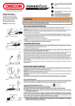
fittings (NPT type threads). (See Figure 2.)
Check the fuel level. If low, fill with unleaded gasoline
with a minimum of 85 octane.
4. HYDRAULIC FLUID
Check the dip stick in the hydraulic fluid reservoir for
the proper fluid level. Use fluids meeting the following
specifications.
VISCOSITY (FLUID THICKNESS)
U.S.
METRIC
50 °F 450 SSU Maximum
10 °C 95 C.S.
100 °F 130-200 SSU
38°C 27–42 C.S.
140 °F 85 SSU Minimum
60 °C 16.5 C.S. Min
Pour Point
-10 °F/-23 °C Minimum (for cold startup)
Viscosity Index (ASTM D-2220) 140 Minimum
Demulsibility (ASTM D-1401) 30 Minutes Maximum
Flash Point
(ASTM D-92) 340 °F/171 °C Minimum
Rust Inhibition (ASTM D-665 A & B) Pass
Oxidation (ASTM D-943) 1000 Hours Minimum
Pump Wear Test
(ASTM D-2882) 60 mg
Maximum
Figure 1. Panel Control Valve
Facing the panel control valve, the bottom male quick
disconnect fitting is the PRESSURE FLUID OUT fitting.
The top female quick disconnect fitting is the RETURN
FLUID IN fitting.
QUICK DISCONNECT COUPLERS
HTMA-approved quick disconnect couplings are
installed to hydraulic hoses so that the direction of
oil flow is always from the male to the female quick
disconnect as shown in Figure 2. Quick disconnect
couplings and hose fittings are selected so that
additional fittings such as reducer or adapter fittings are
not required.
P95 User Manual ◄ 9