1
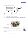
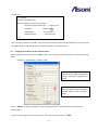
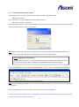
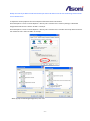
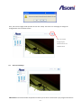
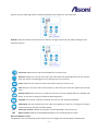
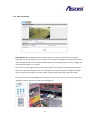
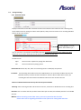
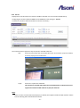
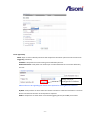
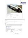
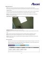
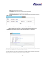
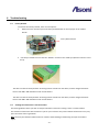
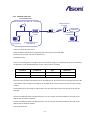
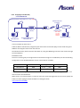
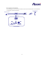
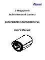
2 Megapixels Bullet Network Camera CAM728MIR/CAM728MIR-PoE User’s Manual -1- Table of Contents 1 Overview .................................................................................................................................................................. - 3 - 2 Product Description .................................................................................................................................................. - 3 2.1 3 4 5 6 7 Hardware Description ............................................................................................................................................ - 4 - Setting up the Network Camera ................................................................................................................................ - 5 3.1 Read Before Use ..................................................................................................................................................... - 5 - 3.2 Hardware Installation Steps ................................................................................................................................... - 5 - 3.3 Open the Housing................................................................................................................................................... - 6 - 3.4 Using the Micro SD Card ........................................................................................................................................ - 6 - 3.5 Using the Terminal Block ........................................................................................................................................ - 7 - 3.6 Re-install the Housing ............................................................................................................................................ - 9 - 3.7 Network Connection for PoE/Non-PoE Cameras ................................................................................................. - 10 - 3.8 Using the Network Camera for the first time ....................................................................................................... - 11 - Accessing the Network Camera .............................................................................................................................. - 12 4.1 Find Camera ......................................................................................................................................................... - 12 - 4.2 Before Assigning an IP Address ............................................................................................................................ - 12 - 4.3 Assigning the IP address to the network camera ................................................................................................. - 13 - 4.4 Access the camera from the browser .................................................................................................................. - 14 - 4.5 The Live View Page ............................................................................................................................................... - 16 - 4.6 iPhone Camera Viewer ......................................................................................................................................... - 18 - Configuring the camera........................................................................................................................................... - 19 5.1 Video Settings ...................................................................................................................................................... - 19 - 5.2 Camera Settings ................................................................................................................................................... - 23 - 5.3 Storage Settings ................................................................................................................................................... - 27 - 5.4 Event Settings ....................................................................................................................................................... - 30 - 5.5 Network Settings .................................................................................................................................................. - 40 - 5.6 System Settings .................................................................................................................................................... - 45 - Troubleshooting ..................................................................................................................................................... - 49 6.1 Factory Default ..................................................................................................................................................... - 49 - 6.2 Viewing the camera from a remote location ....................................................................................................... - 49 - Frequently Asked Questions ................................................................................................................................... - 53 - -2- 1 Overview This camera is a high-end 2 MegaPixel Bullet Network Camera, which is designed for professional outdoor security applications. This network camera is equipped with removable IR-cut filter and Infrared LED, and provides outstanding day and night performance. It comes with a 2 MegaPixel CMOS Sensor, with a maximum resolution of 1600 x 1200, delivering sharp image quality. Furthermore, the dPTZ (Digital Pan/Tilt/Zoom) function allows user to navigate any area of the monitored image with maintained sharp resolution. With unique features, this network camera provides an ideal solution for surveillance and monitoring 2 Product Description Key features 1. H.264 High Profile / MJPEG Dual Compression: Offers the user the option to select H.264 or MJPEG compression. 2. ONVIF ® Compliant for Easy Integration & Fast Deployment: Web services built-in with international standard protocols, integration cycles have been reduced and deployment has become easier. ( Contact your distributor for documentation). 3. Multiple video profiles simultaneously for streaming: Streams up to 8 independent streams with multiple profiles. Different configurations can be set according to the bandwidth that is available from the network. 4. Infrared LED for Day & Night Model, 20 Meters There are 24 infrared LEDs located underneath the transparent cover. 5. Micro SD Card Slot for Local Storage For saving snapshots that can be later checked by the user, upon events occurred during motion detection. 6. Analog Video BNC Out for Video Redundancy on Analog devices The Network Camera has a video output with analog signal that allows connecting to analog monitors. 7. Alarm In & Alarm Out for connecting Alarm Devices The Network Camera comes with a Terminal Block for connecting alarms to execute actions upon it. 8. Power-over-Ethernet IEEE 802.3 af for simplified connection ( Optional) Make installations simple with connecting only one cable without additional powering sources. 9. Weather-proof IP66 rated housing The camera can be shielded from rain and dust. -3- 2.1 Hardware Description Bracket Video out BNC Connector (75 Ohm) for connecting analog monitor Power Jack 12VDC for connecting AC/DC power adapter Ethernet RJ45 Port for network connection Terminal Block (6 pins) for Digital In/Out and load default activation Microphone In (Pink) for connecting a microphone Audio Out (Green) for connecting a speaker -4- 3 Setting up the Network Camera 3.1 Read Before Use The use of surveillance devices may be prohibited by law in your country. The Network Camera is not only a high-performance web-ready camera but can also be part of a flexible surveillance system. It is the user’s responsibility to ensure that the operation of such devices is legal before installing this unit for its intended use. It is important to first verify that all contents received are complete. Take note of the warnings in the Quick Installation Guide before the Network Camera is installed; then carefully read and follow the instructions in the Installation chapter to avoid damage due to faulty assembly and installation. This also ensures the product is used properly as intended. It is designed for various applications including video sharing, general security/surveillance, etc. 3.2 Hardware Installation Steps After unpacking the package and identifying its parts, assemble the network camera to run the device for the first time. It is recommended set up the camera before installing it to the intended location. The following instructions will consist of basic steps that will help you through the hardware preparation. Other required devices before powering up the Network Camera: 1. Personal Computer or Laptop; and 2. Network Hub or Switch and 2 (two) pieces of Ethernet Cable; or 3. 1(one) piece of Crossover Ethernet Cable STEPS: 1. 2. 3. 4. Attach the bracket that comes in the package to the Bracket Nut Hole Connect the Ethernet Plug to the Network Connector RJ-45 from the device Plug the Power Jack to the Power Connector (For Network Cameras that are Power-over-Ethernet supported, the Power Adapter is not necessary) After the Power Connector is plugged in, the Network Camera will boot up. Wait a few seconds for the Network Camera to startup Assemble the Bracket -5- 3.3 Open the Housing The Micro SD card slot and factory default button are located inside the Network Camera. It’s required to open the back cover of the camera and use them. Screws Screws Network Camera body Rubber Ring Back Cover Note: 1. Once the back cover has been Deleted, you will find a rubber ring slightly attached to the inner side of the body of the Network Camera. Don’t lose the rubber ring as it is required to prevent water getting into the camera, as well as for a proper sealing and fitting of the back cover. 2. An additional rubber ring is included in package for spare. 3. It is suggested to reduce the opening of the camera since the unit is intended for outdoor usage. 4. It is recommended the contents of the card be read using from a remote connection. Please refer to the section “5.3 Storage Settings”. Rear View Factory Default Button Micro SD slot 3.4 Using the Micro SD Card The network camera comes with a Micro SD card slot to allow users insert a Micro SD card to save snapshots and videos into it. Refer to Chapter 5) Configuring the camera, Storage Settings and Event Settings. Before plugging / unplugging Micro SD card into / from the slot, it’s recommended to turn the device off. Note: We will not take the responsibility of the damage which made by user when user didn't assembly -6- properly after installing Micro SD card, and caused the unit's waterproof function failed. Note: 1. The device does not support Hot-Swapping function. 2. Tweezers is recommended to help insert the Micro SD card. 3. This unit supports minimum 2GB and max 32GB Micro SD/SDHC card and Class 6 or higher for smooth operation. 3.5 Using the Terminal Block The network camera comes with a Terminal Block Terminal Block Definition that can offer multiple functions to the user: Pin 1 COM (Relay Common) Pin 1 ~ 4: Intended for triggering and receiving alarms Pin 2 D-OUT (Relay Normal for the Event Configuration feature. Open/Close) Pin 5, 6: Terminal block also provides 2 pins, Pin 5 and Pin 3 D-IN (Digital Input) 6, for “load default”. With 2 wires connected to Pin 5 Pin 4 GND (Ground) & 6, keep 2 wires in touch until System LED fast Pin 5 GND (Ground) Pin 6 DEFAULT (Load Default) flashing. Then, separate them to activate “load default”. 1 2 3 4 5 6 Connecting Alarm devices Connect Pin 1 and Pin 2 for an external relay device such as an alarm that expects to be activated. Connect Pin 3 and Pin 4 for an external Triggering device for sending a signal into the Network Camera. Pin 1 Pin 2 Pin 3 Refer to Chapter 5) Configuring the camera, Event Pin 4 Settings for more references on how to use the even trigger and alarm to perform tasks such as taking snapshots and uploading images. Load default With 2 wires connected to Pin 5 & 6, keep 2 wires in touch (or close circuit) until System LED fast flashing. Then, separate (or open) them to activate “load default”. -7- Pin 6 -8- Pin 5 3.6 Re-install the Housing When finishing Micro SD card installation or factory default, please re-install the parts as the following order (A to E) and end up with tightly fastening the screws. A). To ensure water-proof function, do certainly locate the waterproof rubber in place (see the right figure) before installing the back cover. B). Put the PCBA into the camera body. C). Put the desiccant bag in. D). Install the back cover. E). Fasten the screws tightly. Note: 1. There is one additional unopened desiccant (silica gel) inside the housing for spare. 2. To ensure fog-proof function, do replace the desiccant bag with a new one, when it’s necessary to re-install the camera. An unopened silica gel bag can last about 3 months, however, the durability could be shortened under severe environment. 3. Silica Gel is the recommended desiccant type to ensure fog-proof function. If the desiccant bag is run out, please purchase and replace with this type. -9- 3.7 Network Connection for PoE/Non-PoE Cameras The Network Camera comes as an optional model which supports Power-over-Ethernet (PoE). Using Power-over-Ethernet as power supplying mode, takes advantage of having a simple connection, with only one Ethernet Cable to act like Data and Power transmission. And it is not necessary to use any Power Adapter since the powering will be done directly through the Ethernet Connector. Below a comparison between a Regular Ethernet connection and a connection using Network Camera with built-in Power-over-Ethernet. Note: For safety precautions, when using a PoE Video Encoder, ensure that the standard Power Connector has been Deleted before plugging the Ethernet cable (which is attached on the other end to a PoE Hub / Switch). Non-POE Connection Power Adapter Power Adapter Ethernet cable Power Adapter Ethernet cable ADSL Modem Broadband Router Hub / Switch Network Camera Ethernet cable POE Switch & POE Network Camera Power Adapter Ethernet cable Network Camera with Power-over-Ethernet Power Adapter Ethernet cable POE Switch Ethernet cable ADSL Modem Broadband Router POE Single Injector & POE Network Camera Power Adapter Ethernet cable Network Camera with Power-over-Ethernet Power Adapter Ethernet cable POE Injector Hub / Switch - 10 - Power Adapter Ethernet cable Ethernet cable Broadband Router ADSL Modem 3.8 Using the Network Camera for the first time The Network Camera is a network device and its use should be straightforward for those who have basic networking knowledge. Making the initial steps for setting up the network camera will be based on a simple network connection. Option 1 Connect the network camera to a HUB / Switch which is connected to a PC Option 2 Connect the network camera directly to a PC with a crossover cable. After the network camera has its activity lights on, use the PC for setting up the IP Address of the Network camera. Refer to the section of “Accessing the Network Camera” at the next page for detailed instructions. Hints: Possible Network Configurations in your network infrastructure 1. Configuration 1 Internet Access: ADSL or Cable Modem IP address: One real IP or one dynamic IP Connection Type: Only the Network Camera connects to the internet For fixed real IP, set up the IP into the Network camera. For dynamic IP, start PPPoE. 2. Configuration 2 Internet Access: ADSL or Cable Modem IP address: More than one real IP or one dynamic IP Connection Type: The Network Camera and PC connect to the internet Device needed: Switch Hub For fixed real IP, set up the IP into the Network camera and PC. For dynamic IP, start PPPoE. 3. Configuration 3 Internet Access: ADSL or Cable Modem IP address: one real IP or one dynamic IP Connection Type: The Network Camera and PC connect to the internet Device needed: IP sharing such as Hub / Switch and a Router Use virtual IP, set up port forwarding in IP sharing. (Suggestion: Refer to your Network Administrator if necessary for more information) - 11 - 4 Accessing the Network Camera Before getting access to the Network Camera from user’s PC, it’s necessary to properly configure its network setting. This camera uses 192.168.1.200 as the default IP address. If you would like to assign a new static IP address, please install “CAM7 Series Device Search” from the CD-ROM, and then use this program to do that. 4.1 Find Camera 1. Once installed on the PC, click on [Start Menu >> All Programs >> Asoni >> Search Tooling >> Asoni CAM7 Series Device Search] to open the software. 2. The software automatically (or by clicking on “Search” button) displays cameras on the network. Identify your camera by its MAC Address that is shown on the label of the camera. 3. Click on “Web” button or double-click on the identified camera item on the list to launch live viewing (it is assumed that the network cable you’ve connected to your camera has provided a set of useable IP address/subnet mask/Gateway), or click on “Config” button to configuring IP information. 4.2 Before Assigning an IP Address Before assigning an IP address, make sure the Network Camera is powered on and correctly connected to the network. Obtain a LAN IP address not yet used and its related configuration from your network administrator. The following will be required: 1. IP Address 2. Subnet Mask 3. Gateway MAC Address: Each Network Camera has a unique Ethernet address (MAC address) shown on the label of the Network Camera. Hints: When assigning an IP Address User can find necessary IP information by checking the current IP information of user’s host PC via Windows command “ipconfig”: - Click on Windows screen: the Start Menu >> All Programs >> Accessories >> Command Prompt. - Type “ipconfig” at the command prompt to show the current IP information of user’s host PC. - 12 - For example, C:\ >ipconfig Windows IP Configuration Ethernet adapter Local Area Connections: Connection-specific DNS Suffix . : king-tech.com IP Address. . . . . . . . . . . . : 192.168.1.102 Subnet Mask . . . . . . . . . . . : 255.255.255.0 Default Gateway . . . . . . . . . : 192.168.1.254 C:\ > Then, use other IP address 192.168.1.xxx (1-253, except IP address of host PC 192.168.1.102), the same subnet mask 255.255.255.0 and default gateway 192.168.1.254 for the network camera. 4.3 Assigning the IP address to the network camera Select a Network Camera and click on “Setup”. Then, start to configure network settings, such as the following fields: IP Address / Subnet Mask / Gateway / DNS * Remember to input a different value for the last digits of IP address from the “ipconfig”, ranging from 1 to 255. Make sure you enter the same values for Subnet Mask and Default Gateway shown on your “ipconfig” screen. Click on “Update” to apply the changes only by using administrator’s privilege (default user/password = admin/admin). To open the main page of the network camera, select your camera and click on “Web”. - 13 - 4.4 Access the camera from the browser Start the IE browser, type the IP address of the network camera in the address field: http://<IP of camera> If the “HTTP Port” has been changed from “80”, type the URL as: http://<IP of camera>:<HTTP Port> Once the Network Camera is accessed, the Network Camera will request a Username and Password. The default Username and Password is “admin” and “admin”. Note: If “anonymous login” (see 5.6.2) is enabled, the Live View page will be shown without restriction. Or please enter “admin/admin (default account/password)” to pass the authentication. Hints: Changing the root password To avoid security breaches, it is recommended changing the Username and Password once the device is set up to work. Refer to Chapter 5, Configuring the Camera, System Settings. When the Network Camera is accessed via Internet Explorer, it will ask you to install the ActiveX component. Note: during the webpage loading, you may be asked to allow the installation of Active X elements. Please allow it to proceed. Once get accessed, follow the instructions in the manual for the camera operation. If the ActiveX installation doesn't start automatically, please follow below procedures to change security level settings of your Internet Explorer browser. - 14 - Kindly note that if you didn't install ActiveX and you will not be able to see the Live view image. Please make sure to install it first. To adjust the Security Options of Internet Explorer follow the below instructions: Internet Explorer > Tools > Internet Options > Security Tab > Custom Level > Security Settings > Download unsigned ActiveX controls > Select “Enable” or Prompt. Internet Explorer > Tools > Internet Options > Security Tab > Custom Level > Initialize and script ActiveX controls not marked as safe > Select “Enable” or Prompt. When popup the following dialogue box, click “Yes” - 15 - Then, the Live View page will be opened. Click on the “Setup” link of the Live View page to change the configurations of the network camera. Select user interface language: English, traditional Chinese and simplified Chinese 4.5 The Live View Page Video Source: The Stream Profile drop-down list allows you to select a customized or pre-programmed stream - 16 - profile on the Live View page. Refer to Streaming Settings of this chapter for more references. Rotation: allows the rotation of the video to be viewed in an angle of 0 (current), 90, 180 or 270 degrees at a clockwise direction. Full Screen: Maximizes the video to be displayed at a full screen size. Real Size: Displays the real size of the video; (the initial video size will be adjusted to fit your monitor, while the real size could be bigger than it is being shown in the monitor). Listen: allows the user from the PC listen the location where the camera is set. Talk: allows the user from the PC talk remotely to the camera, for which the speaker will emit the voice. Manual Record: Once pressed, it records and saves the currently viewed video the indicated path below. To stop the recording, press back the Recording button. Snapshot: once clicked, it will take a snapshot and save it to the indicated path below. Path Button: Sets the location where the video and snapshot are saved to. To change the location, click on the button and select the desired path. FPS Frames per Seconds: Indicates the quantity of frames displayed in the current view. BPS Bit per second: Indicates the bandwidth allocated for the streaming of the live video. Notes for Windows 7 Users: For Window 7 users, the operating system requires users to configure the Internet Explorer administrator - 17 - setting before the recording and snapshot functions can be enabled. 4.6 iPhone Camera Viewer The network camera provides “iPhone Camera Viewer” for user to monitor via iPhone. Once LAN or internet settings are completed on iPhone, as below, user can monitor via iPhone web browser by just entering the IP address (or domain name) of the network camera. 1). Go to “Settings” to complete network settings, such as WiFi, network (DCHP, BootP, or Static IP). 2). Go to “Safari” and enter the IP address (or domain name) of the network camera, which is followed by an authentication procedure (user/password = admin/admin). Then, Live video page “iPhone Camera Viewer” can be seen. - 18 - 5 Configuring the camera Video Main features and advanced configurations of video streaming. Camera Image adjustments such as brightness, white balance and more. Storage Displays information of the files located in the Micro SD card (if any). Event Smart features for event settings to send emails, snapshots and more. Network Network configuration for the network camera and Event features. System Firmware version information and upgrade, User access management, and system information. 5.1 Video Settings The video settings page contains setting for the streaming 5.1.1 General Settings - 19 - Video General Setting: The Network Camera has in total 8 independent and simultaneous streams which can be used. Your requirements and the properties of your network will determine the type you use. The Live View page in the network camera provides access to a list of streams which are set in this page. They can either be H.264 or Motion JPEG video streams that are configured according to each user’s need. Other applications and clients can also access these video streams/images directly, without going via the Live View page. Stream Types: Stream 1, 3, 5 and 7: H.264 Stream 2, 4, 6 and 8: MJPEG URL ID: Sets the name for the streaming; input an appropriate name to indicate the stream type which is being used. Video Mode: CBR:512 Kbps ~ 4Mbps – Increase CBR to increase the picture quality; or vice versa VBR:The network camera will adjust itself automatically to fit the best picture quality through the bandwidth provided by the network. The balance between VBR and network bandwidth will affect picture quality. Quality Level: There are three levels to adjust: Best, Good and Standard The higher the quality is, the more bandwidth it will use for streaming the video. Resolution: You can set up a different video resolution for different viewing devices. Note that a larger frame size takes up more bandwidth. GOP: GOP stands for "Group of Pictures". The GOP is a group of successive pictures within a coded video stream. Frame Rate: This limits the maximum refresh frame rate per second. Set the frame rate higher for smoother video quality. Target Bit Rates: 512 Kbps ~ 4Mbps – Increase CBR to increase the picture quality; or vice versa. Profile: Providing both of high profile and baseline profile. High profile can deliver better video quality ,but it will cause network camera have larger load relatively. Notes for Stream 1 (H.264) HD: When the Resolution is 1600x1200, the Frame Rate is “15”. When the Resolution is 1280x720, the Frame Rate is 30. - 20 - 5.1.2 Advanced Settings Enable Digital PTZ: The Digital PTZ feature allows you pan, tilt and zoom electronically around the image without having moving parts at the device. Once enabled, it will display a frame which will let you slide it through different areas and automatically zoom the area being focused on, to have a bigger and more detailed image for your viewing. The streams for using Digital PTZ are streams 3/4 and 5/6. Stream 3&4 or stream 5&6 will be enabled respectively when choosing v03 or v05. The naming of the streams by default are v03/04 and v05/06. Such naming can be changed in this same section of Video, going to the page of General settings. Once you tick the box “Enable Digital PTZ” and click on save, you can return to “Live View” and use the navigation interface to browse around zoomed image area. - 21 - Audio Setting Adjust the output gain. Audio Format: select “AAC”, “u-LAW” or “Off” as the audio compression format. The “u-LAW” is highly recommended for 3GPP mobile surveillance (for example, on iPhone or other network-enabled smart phones and NVR surveillance application software). OSD Setting: Camera Name: To display the OSD, type a text on the box with a maximum of 20 characters. Date / Time: Displays the date and time on the video which is streamed from the Network Camera. Save: Once the options have been selected, click on Save to make the changes permanent for the device. - 22 - 5.2 Camera Settings 5.2.1 Camera General Settings Button to save the frame range ! AE Window: The area of selected window will be the auto-exposure sense area for entire camera image. Therefore, if you want to have the image lighting-exposed level depends on particular area, please use the AE Window to select the desired area, otherwise we suggest you selecting the window to cover the central area of the image, same as default setting. Brightness: The image brightness can be adjusted in the range 0-100, where a higher value produces a brighter image. Hue: The image hue can be adjusted in the range 0-100, where a higher value produces more stimulus on the image. Saturation: The image saturation can be adjusted in the range 0-100, where a higher value produces more neutral image. Contrast: The image contrast can be adjusted in the range 1-5, where a higher value produces more - 23 - difference in brightness between adjacent areas. Video Output Format: Select for redundant output (analog monitor) to assign video signal “NTSC” or “PAL”. White balance: This is used to compensate for the different colors present in different light sources, to make the colors in the image appear the same. The Network Camera can be set to automatically identify the light source and compensate for its color. Alternatively, the type of light source can be manually selected from the drop-down list. Exposure: Configure the exposure settings to suit the image quality requirements in relation to lighting, frame rate and bandwidth considerations. Values can be set to: 50 or 60 kHz Max Exposure Time: Select the exposure time for the camera for the duration of the time that gets into the sensor. Max Gain Control: Select the level gain control for the camera ICR: Select “Light Sensor” to activate IR-cut filter or Delete it automatically according to day or night vision. Select “Schedule” to assign the starting time of day mode and night mode. Day Mode/Night Mode: Select “Day Mode” to set time duration for disabling IR. Select “Night Mode” to set time duration and enable IR. GPIN Select “GPIN” to Delete IR-cut filter automatically according to the GPIN status “On” or “Off”. for day Select “On” for day. Select “Off ” for night. Manual: Select “Night” to always Delete IR-cut filter. Select “Day” to always activate IR-cut filter. B/W Mode: Select “By ICR Type” to present image automatically in color or monochrome, which is based on ICR status. When IR-cut filter is off (in case that external IR is on), B/W mode is activated. When IR-cut filter is on, B/W mode is disabled. Select “B/W’ to present image in monochrome (black and white). Select “Color” to present image in its original color. - 24 - Mirror: Flips the video based on Vertical and Horizontal view. 5.2.2 Privacy Window Privacy Window is used to generate an masking area in the video image for protect your personal privacy. To set the privacy window, follow the steps below: 1. Click Add button to create a new window. 2. Use the mouse to decide window size and drag-drop the window. 3. Enter a Window area name. 4. To choice Window color, and click Save to enable the setting. Once configured, the video masking privacy windows will appear in the list of masking area. Note: Up to 6 privacy windows can be set up on the same screen. - 25 - Privacy Window List Add: 6 areas can be set for which they will be identified in 3 colors each, Red, Green or Blue. Once clicked, according to the color selected, a squared block can be drawn on top of the video displayed using the mouse. Press the left click of the mouse to start drawing the box, and drag it upon the video to mark the desired area. Once finished, release the left click of the mouse, and the box will be drawn as intended. Delete: In case any of the area is not required, click on the name of the Area Name from the Privacy Window List, and click on Delete. Windows Area Name: Descriptive name of your choice. Color: 3 colors can be chosen among the areas set for the motion detection; Red, Blue or Green. Save: Once the process has been completed click on “Save” to make the changes permanent. Cancel: in case for any reason, the selection was not properly configured, click on Reset to clear up the values for each feature. - 26 - 5.3 Storage Settings 5.3.1 Disk Information Displays information on the Micro SD Card inserted in the network camera that the user is working with, which will be useful for saving live videos and snapshots, lately used in the built-in live recording Schedule feature of this same section. It won't display if insert Micro SD card not yet ! Click on “Format” to format the inserted Micro SD card. Reminder for first time users, please do it first before you try to read or write into your SD card or update/back up your data. Record Format: Mp4 select to make .mp4 file for playing after download. File select to make file for playing online. Record Stream: Select v01, v03, v05 or v07 streaming which is H.264 (HD) compressed. Pre Alarm: Pre-Recording works when Pre Alarm enabled which is to record video to Micro SD card. The buffered memory in device contains selectable 1~3 Sec Pre Alarm. When alarm occurs, the recording will start and include the buffered video and to save in Micro SD card. Notice: Pre Alarm function will act only after Event system enabled. Warning: when removing the Micro SD card out of the slot, remember to disable the event recording first. Duration: This is to define the time period of each video clips recorded, the available period is from 10~900 seconds. Notice: Before executing record video event, you must synchronize the time first. Please refer to P.47 regarding the details of the options for setting Date and Time. - 27 - 5.3.2 File list Displays the list of files which are stored in the Micro SD Card. User can find the needed files by configuring the duration (between Start time and End time) and clicking on “Search”. A checkbox is shown to allow the deletion of the file if necessary. The network camera supports 2 ways to play the recorded video files: *.file click on the file to play the record video file online. There will be a pop-out window, as below, playing the recorded video. *.mp4: click on the .mp4 file to download. The .mp4 file is encoded with H.264. The used media player on the host PC has to support the H.264-encoded video file to play the video file. Note: There are some recommended media players, as below, that support H.264-encoded video file. Please refer to following webs to download and install. - 28 - QuickTime: http://www.apple.com/quicktime/download/ VLC: http://www.videolan.org/vlc/ KMPlayer: http://kmplayer.en.softonic.com/ - 29 - 5.4 Event Settings The Event Settings page allows the user to customize the Network Camera to perform actions during a period of time, upon the occurrence of certain events in order to have a result. For example: Capture a snapshot, at anytime, when a motion is detected; and send the snapshot to an email address. In simple words: Upon some condition, during a time, do something with a result. The condition will be set by “Trigger by” The time of doing something will be set by “Respond to Trigger” Doing something with a result will be set by “When Triggered…” 5.4.1 Event Configuration Event Type List Add: In order to turn on the capability of setting an Event, go to the Event Configuration page and click on Add to see the available options. Note: the maximum number of events are limited to 10 (ten). Delete: In order to Delete any existing event, click on the name of the Event and click on Delete. - 30 - Event Type Setup Name: Input a name to identify the Event that will perform the action upon some event occurrence. Trigger by: (Condition) Schedule: it will perform an action during a time defined by the user. Motion Detection: it will perform an action upon a motion detected set in some are defined by the user. Please select be configured of windows Please refer to P.35 regarding the details of the options for setting Motion Detection. By Boot: it will perform an action when the camera is booted or restarted. This feature is useful to detect reconnections that are not anticipated or expected. GPIN: it will perform an action when a connected triggering device (at Pin3&4) is activated. - 31 - Respond to Trigger (Activated Time) Always: always keep the Network Camera alert to wait for some condition to happen. Only during time frame: it will perform the action only for the time frame set. This is different from the Schedule condition, since the Schedule condition sets the time as the main reason to start doing something, while the “time frame” sets the duration of the action. Check the corresponding days to execute the triggering time. Start Time: indicates that time that the trigger will be start executing End Time: indicates that time that the trigger will be end executing Interval: indicates the interval between each action. Duration: indicates the duration of the trigger from the Start Time. Temporal Disable: don’t do anything while activated. In other words, even if the condition has happened the Network Camera shall not do anything. This option is useful to pre-set conditions that will probably be used in the future by desire, but that hasn’t to be activated now. When Triggered…(Do some action with a result) - 32 - It won't display if insert Micro SD card not yet ! Upload Images: sends the images to an FTP server. Interval: Set the time between each two notifications. Send Email notification: Send an email message to a predefined email address set in the Network Configuration. - 33 - Interval: Set the time between each two notifications. To: the email account that will be sent to Subject: input the subject of the email Message: write in the message contents Attach file: tick it if you need to attach a file Send HTTP notification: Send a text message as a parameter to an HTTP port that should be expecting a text message or a command. Interval: Set the time between each two notifications. Message: write in the message contents Send TCP notification: Send a text message to an TCP port that should be expecting a text message Interval: Set the time between each two notifications. Message: write in the message contents For configuring the FTP, Email, and TCP settings, refer to the Network Configuration, on Event Server. - 34 - Record to SD: Record video image to SD card. Note: It won't display if insert SD card not yet ! GPOUT: Set to activate a connected device (at Pin1&2) once triggered. When Trigger by: (Condition): Motion Detection、By Boot or GPIN,it would be show below configure. Post Alarm: Set the duration of action after the event 5.4.2 Motion Detection - 35 - Video motion detection is used to generate an alarm whenever movement occurs (or stops) in the video image. A total of 3 Include and/or Exclude windows can be configured. Once configured, the video motion detection windows appear in the list of available triggers, for triggering events. Note: 1. Using the motion detection feature may decrease the camera’s overall performance 2. Don’t set Date & Time of OSD (On-Screen Display) included in the detected area. - 36 - Motion Detection List Add: 3 areas can be set for which they will be identified in 3 colors each, Red, Green or Blue. Once clicked, according to the color selected, a squared block can be drawn on top of the video displayed using the mouse. Press the left click of the mouse to start drawing the box, and drag it upon the video to mark the desired area. Once finished, release the left click of the mouse, and the box will be drawn as intended. Delete: In case any of the area is not required, click on the name of the Area Name from the Motion Detection List, and click on Delete. OSD On/Off: Select “OSD On” to present in screen that Motion Detection is working. Windows Area Name: Descriptive name of your choice Sensitivity: values run from 0 to 100; for which the higher the number, the more sensitive is the motion area. Color: 3 colors can be chosen among the areas set for the motion detection; Red, Blue or Green. Save: Once the process has been completed click on “Save” to make the changes permanent. Cancel: in case for any reason, the selection was not properly configured, click on Reset to clear up the values for each feature. 5.4.3 Event Server Event Servers are used to receive uploaded image files and/or notification messages. To set up Event Server connections in your camera, go to Setup > Event Configuration > Event Servers and enter the required information for the required server type. - 37 - Add FTP: adds an FTP to be used as a recipient for the images Add HTTP: adds an HTTP server to receive text messages. Add TCP: adds a TCP port to received text messages. Add SMTP: adds an Email server/address to receive email messages Delete: to Delete any existing Event Server, select a Name from the Event Server List and click on Delete. Upon clicking on any button to add FTP, HTTP, TCP or SMTP server a box will show up for filling the required information. FTP Server Receives uploaded images Name: Descriptive name of your choice Network address (IP address or host name) User Name and Password: Enter the Username and Password for allowing the upload of the images. Note: Consult your Network Administrator for the correct Username and Password applied to the folder. Make sure that the Username applied in this folder does have Write and Delete permissions to it. In case Write and Delete permissions are not applicable, the intended files to be stored will not take into effect HTTP Server Receives notification messages - 38 - Name: Descriptive name of your choice URL: URL (IP address or host name) Username and Password: Enter the Username and Password for allowing the reception of messages. Note: Consult your Network Administrator for the correct Username and Password applied to the HTTP and Proxy Server. Make sure that the Username applied in the HTTP and Proxy does have Write and Delete permissions to it. In case Write and Delete permissions are not applicable, the intended messages to be delivered will not take into effect TCP Server Receives notification messages Name: Descriptive name of your choice Network Address: IP address or host name Port number: Enter the port number of the TCP service that is expecting to receive the message. Note: Consult your Network Administrator for the availability of the TCP service and Port number to be used. SMTP Server To send email messages - 39 - Name: Descriptive name of your choice Email Address: enter sender’s (the network camera) email address Mail Server: URL of mail server (IP address or host name) Username and Password: Enter the Username and Password for authentication if necessary. 5.4.4 Server I/O GPIO: is used to configure normal circuit status for receiving and triggering Alarms. GPIN 1 Normal Status: sets “Open” or “Close” for the Normal Status of GPIN circuit GPOUT 1 Normal Status: sets “Open” or “Close” for the Normal Status of GPOUT circuit Post Alarm: Set the duration of action after the event happened from 1 ~ 200 seconds. 5.5 Network Settings The Network Settings page allows the user to change and add more sophisticated configurations based on the network infrastructure where the Network Camera is installed. As for the IP Discovery Tool is useful for initial boot up and straight network configuration, the Network Settings page offers a flexible way to fully utilize the network capabilities. - 40 - General: Basic IP configuration settings. Advanced: Page for network settings that include Time Server, Hostname and Port for services. DDNS: Service for accessing the Network Camera through domain names rather than IP addresses. PPPoE: Configuration page for connecting directly to ADSL internet services. Event Server: Sets up the servers utilized in the Event feature page, such as FTP, HTTP, SMTP and TCP. Note: Consult your Network Administrator for the availability of the services and the values for the configuration to be used. 5.5.1 General DHCP: Obtain IP address via DHCP Dynamic Host Configuration Protocol (DHCP) is a protocol that lets network administrators centrally manage and automate the assignment of IP addresses on a network. Although a DHCP server is mostly used to set an IP address dynamically, it is also possible to use it to set a static, known IP address for a particular MAC address. Advise to set IPCHANGE for dynamic IP mode while DHCP service is activated. Static IP Address IP address: Specify a unique IP address for your network camera. Subnet mask: Specify the mask for the subnet the network camera. Gateway: Specify the IP address for the Gateway DNS1: Specify the IP address for the first group of DNS DNS2: Specify the IP address for the second group of DNS PPPoE: The PPPoE feature enables the user to connect the Network Camera directly to the ADSL Modem having direct access to Internet. Click on the PPPoE Enable box to activate the feature, and enter the Username and respective Password. The Username and Password, as well as the internet service that goes with the ADSL Modem are provided by an Internet Service Provider (ISP) such as your local telephone company. Contact your ISP for more information on how to acquire such service. Advise to set IPCHANGE for dynamic IP mode while PPPoE is enabled. - 41 - 5.5.2 Advanced NTP Configuration Obtain NTP server address via DHCP - check this radio button to automatically look up and use the NTP server settings as provided by DHCP. Click the View button to see the current settings. Use the following NTP server address - to create manual settings, check this radio button and enter the host name or IP address of the NTP server. Warning For users using PPPoE as their network access, any change made to the “Network address” of the “NTP Configuration may cause the screen to remain still for a while, because your local ISP (Internet Service Provider) is assigning new IP address and new values for the HTTP, RTSP and FTP ports, whenever a change is made to NTP through PPPoE. Host Name Configuration The network cameras can be accessed using a host name, instead of an IP address. Obtain Host Name server address via ipV4 DHCP - automatically use the DNS server settings provided by the DHCP server. Click the View button to see the current settings. Use the Host Name - enter the desired DNS server by specifying the following: Domain name - enter the domain(s). Multiple domains can be separated by semicolons (;). The host name is always the first part of a Fully Qualified Domain Name, for example, myserver is the host name in the Fully Qualified Domain Name myserver.mycompany.com where mycompany.com is the Domain name. Protocol HTTP The default HTTP port number 80 can be changed according to the user’s need. This is useful for simple security port mapping. - 42 - Note: if you enter a different value other than 80 for your HTTP port, you can not return to the Live View screen. In order to return to the Live View screen, please launch IP Discovery tool again and select your network camera. RTSP The RTSP protocol allows a connecting client to start an H.264/MJPEG stream. Check the box to enable the server and enter the RTSP port number to use. The default setting is 554. Note: that H.264/MJPEG video streams will not be available if this service is not enabled. FTP The FTP server running in the network cameras enables the upload of new firmware, and user applications. Check the box to enable the service. UPnP Setting First, tick the box “Enable UPnP” (actually, it’s ticked in factory default). Arp / Ping Enabling Arp / Ping will offer an additional tool to the user in order to detect the status of the Network Camera. For related commands to ARP/Ping, refer to your Network Administrator. - 43 - 5.5.3 DDNS The DDNS (Dynamic Domain Name Service) feature allows users to access the Network Camera without the need of remembering the IP address, but rather using a name. For example: http://www.mycamera.com Reminder: the DDNS is only effective for PPPoE connection. To be able to use the DDNS feature, a domain name must be registered first in a domain name service from a 3rd party service provider, such as DynDNS (www.dyndns.org). The DDNS feature only forwards the information between the Host Name server and the Network Camera, therefore the Username and Password must be obtained from the 3rd party service provider before using the feature. Note: Refer to your Domain Name Service Provider for more information on setting up a domain name. Some Domain Name Service providers charge a fee for the registration, while some offer the service as free of charge. It will be in the user’s decision which service to acquire. In order to use the DDNS feature, it is assumed that the Network Camera already has direct access to Internet. For more information on how to allow the Network Camera to access the Internet, consult with your Network Administrator and you can also refer to the Port Forwarding Section in this manual for a basic guide line and a better understanding of the topic in matter. - 44 - 5.5.4 IPCHANGE Settings This setting triggers an email sending to notify the latest IP address when the IP address of this network camera is changed. Please configure SMTP Server information (Network -> Event Server) first. IPCHANGE: Disable or Enabled SMTP Server: Select one on the list of configured Email servers Mail To: Set the destination (e.g. [email protected]) which the alerting email is sent to. Click on “Save” to apply the change. 5.6 System Settings 5.6.1 Information - 45 - The System Settings page displays information about the current status of the Network Camera. Such information is useful to have references when direct information is required without going through the different pages of configuration of the Network Camera. 5.6.2 User The user configuration page allows the Network Camera to have multiple users and profiles to access the Network Camera. Enable anonymous login: To allow the access to the Network Camera without restrictions, select the box of Enable anonymous login and click on “Save” to make the changes permanent. Such change will allow anyone to access the Network Camera without a username or password. Note: it is in the user’s discretion whether or not to allow authorized and unauthorized to access the Network Camera. Adding a user In order to add a new user, click on the “Add “button and fill the information which is required. After filling the information, click on “Save” to make changes permanent to the device. Administrator: Permission to view and change the configuration of the Network Camera. - 46 - Operator: Has permission as Administrator, but not for Network and System. Viewer: Has only permission to view the Network Camera. Note: follow the instructions displayed on the User’s page while selecting of a Username and Password. Deleting a user To delete user, click on a Name from the Users list and click on “Delete”, then click on “Save” to make the changes permanent. 5.6.3 Date & Time Displays the date and time (24 hours clock) of the Network Camera. Set Server Time Select the Automatically adjust for daylight saving time changes if necessary. From the Time Mode section, select the preferred method to use for setting the time: Synchronize with computer time - sets the time from the clock on your computer. Synchronize with NTP Server - the camera will obtain the time from an NTP server every 60 minutes. Set manually - this option allows you to manually set the time and date. Note: If using a host name for the NTP server, a DNS server must be configured under Network Settings. Click on “Save” to make the changes permanent. In case there was error during the selection, click on “Reset” and restart the process. - 47 - 5.6.4 Server Maintenance The Server Maintenance page allows the user to make changes in the Network Camera, such as: Reboot: restarts the Network Camera Load Default: sets the Network Camera back to the default parameters from factory. Upload File: Upgrades the Network Camera to a new released firmware. Look up for the file and select it. Click on “Upgrade” to proceed with the upgrading of the firmware. Notes: if you plan to upload older firmware versions, please keep in mind there could be possible risks that some functions might not work properly. Note: if you enter a different value other than 80 for your HTTP port, you can not return to the Live View screen. In order to return to the Live View screen, please launch IP Discovery tool again and select your network camera. Restore: Look up for the file that restores a previous configuration of the Network Camera. Click on “Upload“ to begin the process. Backup: click on “Backup” to save the current parameters of the Network Camera to a file. Note: 1. Please do not restore previous configuration file into camera which has been upgraded with new firmware version. It may lead to malfunction. 2. Before making any changes to the system of the Network Camera, make sure it is what is required while all alternatives have been considered and executed. - 48 - 6 Troubleshooting 6.1 Factory Default To execute the Factory Default, there are two options: 1. Delete the cover and then press the factory default button on the top layer of the module boards. Factory Default Button 2. Use two pin needles to insert into the “Default” and one of the “GND” pin (which are the Pin 5 and Pin 6). The device is back to factory default. All settings will be erased from the device, and the assigned IP will be back to 192.168.1.200 and Subnet mask to 255.255.0.0. The device is back to factory default. All settings will be erased from the device, and the assigned IP will be back to 192.168.1.200 and Subnet mask to 255.255.0.0. 6.2 Viewing the camera from a remote location The below guideline shows you how to setup the Network Camera for viewing it from a remote location. The network infrastructure demonstration is just for your reference only. Each network infrastructure may vary upon the needs of the organization. Note: Consult your Network Administrator for a better understanding of networking concepts and related topics. - 49 - 6.2.1 Standard connection Local Network Network Camera 192.168.1.21 / Port 80 Internet Service Provider Internet Broadband Router Terminal 192.168.1.22 ADSL Modem Public IP 210.20.34.23 Remote Location Company Web Server 192.168.1.23 In this case what we have here is: Public IP Address 210.20.34.23, assigned by the Internet Service Provider (ISP) Network Camera, with a local IP of 192.168.1.22 Broadband router Since we are sharing only one single Internet connection through our Local Network, the Port Forwarding configuration in our Broadband Router for the camera will be as follows: Private IP Private Port Type Public Port 192.168.1.22 80 ● TCP ○ UDP 80 192.168.1.22 554 ● TCP ○ UDP 554 Notice that the Port 80 is the default port for any Web-Server, but this also can be changed. Since Port 80 is the default, when we type our IP address at the Address bar, there won't be any need to type the port number. The default port for streaming an H.264 video is port 554, being the same as the port 80, it can also be changed. Once the broadband router's configurations are set, we can open the Internet Explorer and type in the Address bar the Public IP address. Once the broadband router's configurations are set, we can open the Internet Explorer and type in the address bar the Public IP address. http://210.20.34.23/ - 50 - 6.2.2 Assigning Ports Manually Local Network Network Camera 192.168.1.21 / Port 8080 Internet Service Provider Internet ADSL Modem Broadband Router Terminal 192.168.1.22 Public IP 210.20.34.23 Port 8080 For the Network Camera Remote Location Company Web Server 192.168.1.23 In this case what we have here is: Public IP Address 210.20.34.23, assigned by the Internet Service Provider (ISP), but we will be using Port 9999 for accessing the camera from the Internet. The Network Camera, with a local IP of 192.168.1.22, using port 8080 to get access to the camera through the Local Network. Broadband router Since we are sharing only one single Internet connection through our Local Network, the Port Forwarding configuration in our Broadband Router for the camera will be as follows: Private IP Private Port Type Public Port 192.168.1.22 8080 ● TCP ○ UDP 8080 192.168.1.22 554 ● TCP ○ UDP 554 In this case we are using Port 8080 for the Network Camera at 192.168.1.22, and using Port 8080 for the Internet access at 210.20.34.23. When we are in a remote location, in order to access our camera through Internet, we have to specify the Public Port when typing the Public IP Address as the figure below http://210.20.34.23:8080/ - 51 - 6.2.3 Using two ore more public IPs The following figure is just an illustration on how the camera can be connected when 2 or more Public IPs are involved in a network infrastructure Internet Service Provider Network Camera Hub / Switch ADSL Modem Public IP Broadband Router Company Web Server 192.168.1.23 Terminal 192.168.1.22 Local Network - 52 - 2 Public IP 7 Frequently Asked Questions Symptoms, Possible Causes, and Remedial Action Problems setting the IP address The camera is located on a different subnet If the IP address intended for the camera and the IP address of your computer are located on different subnets, you will not be able to set the IP address. Contact your network administrator to obtain an appropriate IP address. The IP address is being used by another device Disconnect the camera from the network. Run the Ping command. (In a Command/DOS window, type ping and the IP address of the unit). If you receive: Reply from <IP address>: bytes = 32; time = 10 ms..... - this means that the IP address may already be in use by another device on your network. You must obtain a new IP address and reinstall the unit. If you see: Request timed out - this means that the IP address is available for use with your camera. In this case, check all cabling and reinstall the unit. Possible IP address conflict with another device on the same subnet The static IP address in the camera is used before the DHCP server sets a dynamic address. This means that if the same default static IP address is also used by another device, there may be problems accessing the camera. To avoid this, set the static IP address to 0.0.0.0. The camera cannot be accessed from a browser The IP address has been changed by DHCP If the camera and client are on the same network, run the IP Discovery Utility to locate the camera. Identify the camera using its model or serial number Alternatively: 1) Move the camera to an isolated network or to one with no DHCP or BOOTP server. Set the IP address again, using the IP Discovery Utility (see the Installation Guide) or the ARP/Ping commands. 2) Access the unit and disable DHCP in the TCP/IP settings. Return the unit to the main network. The unit now has a fixed IP address that will not change. 3) As an alternative to 2), if dynamic IP address via DHCP or BOOTP is required, select the required service and then configure IP address change notification from the network settings. Return the unit to the main network. The unit now has a dynamic IP address, but will notify you if the address changes. Other networking problems Test the network cable by connecting it to another network device, then Ping that device from your workstation. See instructions above. Camera is accessible locally, but not externally Broadband router configuration To configure your broadband router to allow incoming data traffic to the camera, enable the NAT port forwarding feature which will configures the router to allow access to the camera. Firewall protection Check the Internet firewall with your system administrator. Default routers required Check if you need to configure the default router settings. Problems with the H.264/MJPEG format No H.264/MJPEG displayed in the client Check with your network administrator to see if there is a firewall preventing viewing. Poor rendering of H.264/MPEG-4 images Color depth set incorrectly on clients. Set to 16-bit or 32-bit color. Ensure that your graphics card is using the latest device driver. The latest drivers can usually be downloaded from the manufacturer's web site. Color saturation is different in H.264 and Motion JPEG - 53 - Modify the settings for your graphics adapter. Please see the adapter's documentation for more information. Lower frame rate than expected Reduce number of applications running on the client computer. Limit the number of simultaneous viewers. Check with the system administrator that there is enough bandwidth available. See also the online help. Lower the image resolution. No images displayed on web page Installation of additional ActiveX component restricted Configure your Internet Explorer to allow the installation of ActiveX by lowering temporally the Internet Explorer security settings. Video/Image problems, general Image too dark or too light Check the video image settings. Missing images in uploads This can occur when trying to use a larger image buffer than is actually available. Try lowering the frame rate or the upload period. Slow image update Configuring pre-buffers, motion detection, high-resolution images, or high frame rates, will affect the performance of the camera. Poor performance Poor performance may be caused by heavy network traffic, multiple users accessing the unit, low performance clients, use of features such as Motion Detection, Event handling. Poor quality snapshot images Screen incorrectly configured on your workstation In Display Properties, configure your screen to show at least 65000 colors, that is, at least 16-bit. Using only 16 or 256 colors will produce dithering artifacts in the image. Audio volume too low/high Volume settings incorrect The volume of the microphone is either too high or too low. Change the volume for the microphone in the toolbar on the Live View page. Poor audio quality CPU overloaded Reduce the number of listeners and viewers and decrease the image resolution and compression. Unsynchronized audio and video It is recommended that the camera's time setting is synchronized with an NTP Server. This is enabled under System Options > Date & Time. Distorted audio Select Microphone for the internal microphone or for a connected external microphone. Select Line for a connected line in source. - 54 -