1
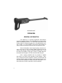
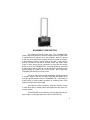
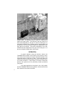
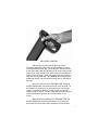
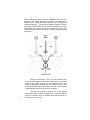
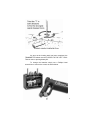
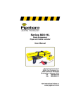
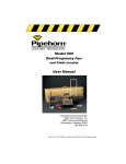
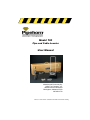
Model 100
Pipe and Cable Locator
User Manual
Manufactured Exclusively By:
Utility Tool Company, Inc.
2900 Commerce Boulevard
Birmingham, Alabama 35210
205-956-3710
1
Under U.S. Pat # 3418572 Canadian Pat # 857504 Other Patents Pending
DANGER! SHOCK HAZARD
CONNECTING DIRECTLY TO ANY CONDUCTOR
CAN BE HAZARDOUS AND RESULT IN ELECTRIC
SHOCK, INJURY, OR DEATH. ONLY LICENSED OR
AUTHORIZED PERSONS SHOULD MAKE DIRECT
CONNECTIONS TO POTENTIALLY ENERGIZED CONDUCTORS.
This device complies with Part 15 of the FCC Rules.
Operation is subject to the following two conditions: (1)
this device may not cause harmful interference, and (2)
this device must accept any interference received, including interference that may cause undesired operation.
NOTICE
This User’s Manual is provided as an informational
guide only and is subject to change without notice.
This Manual contains certain information which is
proprietary in nature and protected by U.S. and Foreign
Patents, Copyrights, and Registered Trademarks. All
rights are reserved. No part of this document may be photocopied, reproduced, transmitted, or converted into another language without the express written consent of Utility Tool Company, Inc.
Copyright © Utility Tool Company, Inc. 2003
2
CONTENTS
Section Title
Page
General Information
4
Equipment Description
5
Operation
6
Battery Locations
9
Maintenance
10
Repair or Service
11
3
RECEIVER UNIT
PIPEHORN
GENERAL INFORMATION
The Pipehorn is a carefully engineered, hand-crafted,
precision instrument which, with reasonable care, will give many
years of satisfactory service. It is the finest instrument on the
market today for locating underground or concealed piping, tubing or cable. It is very simple to use but for best results you
should carefully read these instructions and be guided by them.
Since the Pipehorn uses a high frequency electrical current, it can only be used to locate metallic structures such as
steel or cast iron pipe, copper or aluminum tubing or wire. It can
be used to find plastic or clay pipe if a wire or metallic tape can
be inserted into the pipe or if a wire was buried with the pipe.
Soil or paving materials such as concrete or asphalt
have little or no effect on the operation of the Pipehorn. However, reinforced concrete contains a network of metal which will
interfere with the proper operation of the instrument, and it usually cannot be employed to locate structures underneath or behind reinforced concrete, metal lath or similar materials.
4
TRANSMITTER UNIT
EQUIPMENT DESCRIPTION
The instrument consists of two units. The TRANSMITTER,
which is the small black box, produces a high frequency signal which
is reproduced in the pipe by one of two methods. When it is placed
in the area of the pipe with its longest dimension parallel to the pipe,
it will inductively create a similar signal in the pipe. It may also be
directly connected to the pipe at a water faucet, gas meter, water
meter or other above ground connection by using the two binding
posts on top of the TRANSMITTER. One post should be connected
to the structure and the other to a metal rod which is pushed into the
ground nearby to a depth of six or more inches. Do not place the
TRANSMITTER directly on metal covers.
The latter method has certain advantages in that it produces
a stronger signal in the pipe and thus allows the RECEIVER to be
used at a greater distance from the TRANSMITTER. It also helps to
avoid picking up other nearby structures by confining most of the
signal to the structure being sought.
The inductive method, however, produces excellent results
in most cases and is certainly faster and simpler than the direct connection method.
The RECEIVER unit contains the receiving apparatus to pick
up the signal, a sound generator and a device to produce an
5
audible signal. Its operating controls consist of a spring return
switch and a gain control. The purpose of the gain control is to
allow exact pinpointing of the pipe or cable by reducing the instrument’s sensitivity to the locating signal to a point which will
just produce a low tone when the head of the RECEIVER is exactly above the structure. By careful manipulation of the RECEIVER head and adjustment of the gain control the pipe or cable can usually be located within a few inches.
OPERATION
In normal operation using the inductive method, the
TRANSMITTER is placed on the surface of the ground or pavement with the box having its longest dimension parallel to the
suspected location of the pipe or cable. It should be placed directly over the structure if its location is known, such as at a meter or other connection. If the location is not known it should be
placed in the general area for preliminary location procedures
(see photo).
The switch should then be placed in the “ON” position
and the TRANSMITTER left in this position until the structure has
been spotted in the manner described.
6
ADJUSTING CONTROL
With the gain control turned all the way counterclockwise, move away about ten feet and depress the switch
on the RECEIVER hand grip. The head (the cross-like section
at the end of the probe rod) should be held close to the ground
with the two cross ends in a line which crosses the suspected
location of the structure. When the head is over the structure a
deep tone will be produced. The TRANSMITTER may now be
positioned exactly over the structure should this not already be
the case.
Now move away from the TRANSMITTER, sweeping
the RECEIVER head over the surface until a tone is heard. As
the distance is increased, it will be necessary to turn the gain
control in a clockwise direction in order to pick up sufficient
signal to produce a tone. Careful manipulation of the head and
control will allow the structure to be located within a few
inches.
When the distance between the TRANSMITTER and
the RECEIVER has reached a point where no sound is produced with the control turned fully clockwise, the last located
7
position should be marked and the TRANSMITTER moved to
that point. The same procedure can then be followed as described above. Using this system the pipe can be followed for
unlimited distances. (The maximum distance between TRANSMITTER and RECEIVER will vary with soil conditions and other
factors and may range from several hundred feet under good
conditions down to as little as fifty or so under extremely adverse
conditions.)
PINPOINTING
When two structures, such as gas and water mains,
are fairly close together, care must be exercised in the adjustment of the control so that the unit responds only to the
stronger signal which radiates from the desired structure. Use
of the direct connection system may make it far easier to differentiate between structures under such conditions.
Although the Pipehorn is easy to use, a little training
and practice will increase its effectiveness. Practicing with the
unit over a known main is an effective and practical way to improve one’s skill in its use.
8
FINDING CONDUCTOR DIRECTION
As soon as the locating work has been completed, the
TRANSMITTER switch must be FLIPPED TO THE “OFF” POSITION in order to prolong battery life.
To change the batteries simply use a Phillips Head
screw driver to remove the covers as shown below.
9
MAINTENANCE
Your Pipehorn was carefully pre-adjusted at the factory and no
further internal adjustments should be required. It is constructed entirely
of solid state devices and, therefore, contains no tubes to burn out. With
reasonable care it should have an indefinite useful life.
Each of the two units contains batteries for their power source
and they should be changed periodically. Naturally the life of the battery
is determined in large measures by the extent of usage of the device.
Should the sound become weak, the operating distance decrease, or
should the instrument become inoperative, it is likely the result of dead
batteries. Batteries should be changed as needed, but additionally it is
recommended that they be changed once every six months to be certain
that the instrument will be ready to operate when needed.
NOTE: The usual reason for an inoperative TRANSMITTER unit
is that the switch was not returned to the “OFF” position when the work
was completed. Operators should be careful to turn the unit “OFF” after
each job.
Use the following batteries:
Transmitter:
Receiver:
6 alkaline “AA” cells
One 9-volt alkaline cell
WARRANTY
THERE ARE NO WARRANTIES, EXPRESS OR IMPLIED, INCLUDING
ANY WARRANTY OF MERCHANTABILITY, BEYOND THOSE STATED
BELOW.
Utility Tool Company, Inc. warrants the equipment it manufactures to be
free from defects in workmanship or material, under normal and proper
use and service by the original user, for three years from the date of
original shipment from the factory. Batteries and other expendable items
are not included in this Warranty. Unauthorized repair, alteration, or
improper maintenance will void this Warranty. Alteration or removal of
the serial number will also void the Warranty. Utility Tool Company will
not be obligated under this Warranty if the equipment has been misused,
misapplied, or accidentally damaged.
If a product is found defective under this Warranty, Utility Tool Company
10will, at its option, repair or replace the unit free of charge at Utility Tool
Company’s factory. The unit should be returned to the factory prepaid with customary shipping precautions. Utility Tool Company’s
obligations under this Warranty are limited to the repair or replacement of defective parts which are not the result of alteration, misuse,
abuse, or accidental damage, or at the option of Utility Tool Company, the refund of the purchase price. Utility Tool Company assumes no other liabilities, contingent or consequential, to any equipment found defective under this Warranty.
REPAIR OR SERVICE
For fast service (48 hour turnaround from when we receive
it), return the unit in its wooden carrying case prepaid to:
Service Department
Utility Tool Company, Inc.
2900 Commerce Blvd.
Birmingham, Alabama 35210
Phone (205) 956-3710
If you have questions or suggestions regarding our equipment or a particular application, contact our applications support
group at the number listed above between 8:00 am and 4:30 pm
Central Time. Thank you for purchasing Pipehorn equipment. We
value your business and want to keep it. Please fill in the following
for your records:
Pipehorn Model 100 Serial Number:_____________________
Date of Purchase: ___________________________________
WHEN MARKING UTILITIES
Use the APWA Uniform Color Code for marking buried utilities. This
code is used to identify the various types of underground utilities.
Make sure the color you use corresponds to the chart below for the
type of utility you are marking.
Electric Power Lines or Conduits
Communication Lines or Cables
Storm & Sanitary Sewers
Water
Gas
Proposed Excavation Area
Safety Red
Safety Alert Orange
Safety Green
Safety Blue
Safety Yellow
High Visibility White
11
12