1
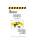
Model 500
Dual-Frequency Pipe
and Cable Locator
User Manual
Manufactured Exclusively By:
Utility Tool Company, Inc.
2900 Commerce Boulevard
Birmingham, Alabama 35210
205-956-3710
Under U.S. Pat # 3418572 Canadian Pat # 857504 Other Patents Pending
DANGER! SHOCK HAZARD
CONNECTING DIRECTLY TO ANY CONDUCTOR CAN BE HAZARDOUS AND RESULT IN ELECTRIC SHOCK, INJURY, OR
DEATH. ONLY LICENSED OR AUTHORIZED PERSONS SHOULD MAKE DIRECT
CONNECTIONS TO POTENTIALLY ENERGIZED CONDUCTORS.
This device complies with Part 15 of the
FCC Rules. Operation is subject to the
following two conditions: (1) this device
may not cause harmful interference, and
(2) this device must accept any interference received, including interference that
may cause undesired operation.
NOTICE
This User’s Manual is provided as an informational guide only and is subject to change
without notice.
This Manual contains certain information
which is proprietary in nature and protected
by U.S. and Foreign Patents, Copyrights,
and Registered Trademarks. All rights are
reserved. No part of this document may be
photocopied, reproduced, transmitted, or
converted into another language without the
express written consent of Utility Tool Company, Inc.
Copyright © Utility Tool Company, Inc. 1992
2
6/6/14 12:39 PM
CONTENTS
Section Title
Page
General Information
The Equipment
Why Two Frequencies?
Why Two Transmitters?
Advantages Of The Model 500 System
Safety
The Manual & Terminology
Quick-Start Instructions
High-Frequency Inductive Locating
Low-Frequency Conductive Locating
Description of Equipment & Principles of Operation
High-Frequency Transmitter Operation
Low-Frequency Transmitter Operation
Receiver Operation
Tracing When There is No Access to the Conductor
Searching For a Conductor Whose Location is Unknown
When There Is One Operator
When Two People Are Available
Tracing From An Access Point
Maintenance
Batteries
Warranty
Repair Service
3
6/6/14 12:39 PM
LIST OF FIGURES
NUMBER
1.
2.
3.
4.
5.
6.
7.
8.
9.
10.
11.
12.
13.
14.
15.
16.
17.
18.
19.
DESCRIPTION
PAGE
Model 500 and Accessories (Photo)
HF Inductive Locating (Quick Start)
LF Conductive Locating (Quick Start)
HF Transmitter and Conductive Cables (Photo)
HF Transmitter Inductive Setup
HF Transmitter Conductive Setup
LF Transmitter and Conductive Cables (Photo)
LF Transmitter Conductive Setup
Dual Frequency Receiver (Photo)
Pinpointing on a Slope - Hold Receiver Vertical
Do Not Swing (or Arc) Tee Antenna
Apply HF Signal Inductively
Adjusting the SENSITIVITY CONTROLTM
Pinpoint the Conductor
Verify the Conductor Pinpointed
Positioning HF Transmitter for One Person Search
Pinpoint with Receiver and HF Transmitter
Check for Air-Coupling
Transmitter Battery Replacement Photo
4
6/6/14 12:39 PM
General Information
The Pipehorn Model 500 is a state-of-the-art, dual-frequency locating system designed for the professional with complex locating jobs. It is a carefully
engineered, precision instrument that, with reasonable care, will give many
years of satisfactory service. The Model 500 is very simple to operate, but
for best results, the operator should carefully read this manual.
The Equipment
The Model 500 consists of a receiver, two transmitters, two sets of conductive hook-up cables, a grounding spike, and an earphone, all contained in a
sturdy wooden case.
Model 500 - Complete
The Model 500 is really two tools combined into one for attacking any locating job. It can operate as a low (audio) frequency, conductive locator and as
a high (radio) frequency, inductive or conductive locator. The Model 500 is
used to locate and trace all types of buried or concealed conductors such
as: pipe, cable, tracer wire, traceable fiber optics, or even sewer snakes or
fish tape inserted into non-conductive pipe.
5
6/6/14 12:39 PM
Why Two Frequencies?
Every locating job is different. Success calls for a unique blend of equipment, experience, and persistence. In some situations, a low-frequency,
conductive locator will perform better than a high-frequency, inductive
locator. In other situations, the reverse is true.
The advantage of the low-frequency locator is long distance tracing and,
in some cases, isolating one conductor from another. These advantages are usually most apparent on insulated conductors such as,
wrapped pipe or cable. The disadvantage of low-frequency is that it
must be directly connected to the pipe or cable.
The high-frequency locator traces poor conductors (cast and ductile iron)
and short lengths (stubs, laterals and tracer wire) better than a lowfrequency locator. It does not have to be connected directly to the pipe
or cable, though this method is available. Inductive operation is much
faster and easier since the transmitter is just placed over the conductor.
Its inductive capabilities allow the operator to move the signal injection
point to any place which is useful. Using the high-frequency inductively
gives the locator unlimited range simply by moving the transmitter. Additionally, inductive locating is safer to use on live power cables and sensitive fiber optic lines. The disadvantage of high-frequency, inductive operation is that when trying to target one conductor, it can place more
signal on adjacent conductors, making isolation more difficult.
Why Two Transmitters?
Two transmitters enable the operator to do a number of things that
would not be possible using a single transmitter. First, the range of the
low-frequency transmitter can be extended by placing the highfrequency transmitter down at the last known point to continue tracing.
Second, the high-frequency transmitter can be used to verify the lowfrequency locate. For instance, trace from a known point using the lowfrequency, pinpoint the conductor, place the high-frequency transmitter
down, and trace back to the known point as a crosscheck. Third, two
transmitters and two frequencies can be used to identify different conductors buried close to each other. As an example, apply the lowfrequency signal to the gas service and the high-frequency signal to the
water; identify each conductor by its frequency.
6
6/6/14 12:39 PM
Advantages of The Model 500 System
Combining a low-frequency and high-frequency locator into one unit gives
the operator the necessary tools for solving complex locating jobs easier.
One frequency usually performs well where the other does not. Having two
transmitters offers many advantages, such as enabling the operator to trace
farther. Also, verification and identification of conductors is much easier and
faster. In short, the Model 500 Professional Pipe & Cable Locator is a more
complete and productive tool for the experienced user.
SAFETY FIRST!
DANGER! Shock Hazard. Connecting directly to any conductor can be
hazardous and result in electric shock, injury, or death. Only licensed
or authorized persons should make direct connections to potentially
energized conductors.
Always exercise good safety procedures when operating locating equipment. These include, hooking a transmitter directly to energized conductors
only when licensed or authorized, being constantly aware of traffic and
equipment operating nearby, and removing any flammable or toxic liquids
and gases from the area before using a locator. Employing proper safety
practices during locating tasks will perhaps avoid an accident and may
save your or another person’s life .
Use the APWA Uniform Color Code for marking buried utilities. This code is
used to identify the various types of underground utilities. Make sure the
color you use corresponds to the chart below for the type of utility you are
marking.
•
Electric Power Lines or Conduits
Safety Red
•
Communication Lines or Cables
Safety Alert Orange
•
Storm & Sanitary Sewers
Safety Green
•
Water
Safety Blue
•
Gas
Safety Yellow
•
Proposed Excavation Area
High Visibility White
7
6/6/14 12:39 PM
The Manual & Terminology
This manual tells you how to operate the Pipehorn Model 500. The
locator requires no calibration or adjustment and arrives from the factory
ready to use. Maintenance is limited to the replacement of batteries. In
this manual you will find information that will help you locate buried
pipes and cables successfully. The main areas covered are:
•
•
•
•
•
Description of Equipment & Principles of Operation
System Check
Tracing When There Is No Access
Searching For Utilities Whose Location Is Unknown
Tracing From an Access Point
When the following terms are used in this manual, they have the meanings specified below:
Conductor - pipe, cable, conduit, traceable optic fiber, tracer wire/tape,
sewer snake, fish tape, or other conductor
Tracer Signal or Signal - the output from a transmitter, either directly or
through the air, which is carried along the conductor and detected
with the receiver
Inductive - place the tracer signal on the conductor with out making
direct electrical contact
Conductive - place the tracer signal on the conductor by making a direct hook-up
LF - low-frequency (audio-frequency)
HF - high-frequency (radio-frequency)
Sensitivity - the amount of signal the receiver is set to detect; increasing the sensitivity allows the receiver to detect weaker signals
when it is farther from the transmitter or conductor.
8
6/6/14 12:39 PM
Quick Start Instructions
The procedures below provide the information for experienced operators of
locating equipment to begin using the Model 500 immediately. Even if you
have a lot of experience with locating equipment, it will benefit you to become familiar with this entire manual.
High-Frequency Inductive Locating
1. Place the HF (black with the tall aluminum handle) Transmitter directly
over and in-line with the run of the conductor. Flick the switch to ON.
Inductive
(No Connection)
•
Null (No Signal)
•
Place the transmitter
directly over and in line
with the target conductor
to maximize the signal.
Adjacent conductors may
be close enough to pick
up some signal
Adjacent Conductor
Target Conductor
2. Move 5 to 10 steps away from the Transmitter and press the "H" on the
Signal Source Switch on the right side of the Receiver to receive the HF
signal. Energize the Receiver by squeezing the push button switch on
the handle. Position the tee antenna at the base of the Receiver so that
it is across the run of the conductor.
9
6/6/14 12:39 PM
3.
Adjust the SENSITIVITY CONTROLTM to acquire a steady, nonbeeping tone. A beeping tone is the SENSITIVITY CONTROLTM saying there is too much sensitivity, turn it down. Scan left and right of the
conductor listening for the shrill sound on either side and the deep tone
over the conductor. When you hear the deepest tone, the Receiver is
pointed at the conductor.
Pinpointing with Pipehorn
Language
Shrill Sound
Deep Tone
Weak Signal
Strongest Signal
Shrill Sound
Weak Signal
Balanced Signal
4. Pinpoint the conductor and then check for air lock by pointing the Receiver tee at the Transmitter. If the sound goes away the conductor is
the source and you can begin tracing. If it does not, the signal may be
coming directly from the Transmitter and you should move farther
away. The tee antenna, which is at the base of the Receiver, should be
positioned across the run of the conductor.
Check for Air Coupling
•
•
•
After pinpointing, raise the receiver and point it at the transmitter
If you are too close, the signal gets stronger
If you are far enough away, the signal gets weaker as you lift the
receiver
Signal mostly from transmitter, tone goes
deeper or beeps
Signal mostly from conductor, tone
goes shrill or stops
Conductor
10
6/6/14 12:39 PM
Low-Frequency Conductive Locating
LF Transmitter and Connector Cables
1. Position the ground spike at 90o to the run of the conductor and as far
from the connection point as the cables will allow. This will minimize
tracer signal on any adjacent conductors. Connect one clip to the
ground spike. Connect the other clip to the target conductor being sure
to make good electrical contact. This contact and the ground are essential in placing a good signal on the target conductor.
Conductive
(Direct Hook Up)
•
Red to Target
Black to ground
•
•
Must have access to metal of
the target conductor (remove
insulation, rust or paint)
Connect red terminal to the
target
Connect black terminal to
ground placed 90 o and as far
away from target conductor as
possible
Side View
2. Energize the target conductor by inserting the plug into the LF (yellow
11
6/6/14 12:39 PM
handle) Transmitter.
3. Move 4 to 5 steps away from the Transmitter and press the
“L" (yellow) on the Signal Source Switch on the right side of the Receiver to receive the LF signal. Energize the Receiver by squeezing
the push button switch on the handle. Position the tee antenna at
the base of the Receiver so that it is across 90o the run of the conductor.
4. Adjust the SENSITIVITY CONTROLTM for a steady, non-beeping
tone. A beeping tone is the SENSITIVITY CONTROLTM saying
there is too much sensitivity, turn it down. Scan left and right of the
conductor listening for the shrill sound on either side and the deep
tone over the conductor. When you hear the deepest tone, the Receiver is over at the conductor.
5. Trace 20 to 30 feet carrying the HF Transmitter, pinpoint and mark
"the conductor. Verify the identity of the conductor by placing the
HF Transmitter down on the mark, setting the Signal Source Switch
to the HF position, and tracing back to the hook-up point.
6. With verification complete, trace the LF signal while carrying the HF
Transmitter. Use the HF Transmitter to extend the range or identify
adjacent or crossing conductors, as needed.
Description of the Equipment & Principles of Operation
HF Transmitter
The HF transmitter is the black box with the aluminum handle, red and
black terminals on top, and ON/OFF switch . The HF Transmitter is supplied with the conductive hook-up cables shown.
HF Transmitter & Cables
12
6/6/14 12:39 PM
HF Transmitter Inductive Operation
The HF Transmitter places a radio frequency tracer signal on the conductor by one of two methods, inductively or conductively. When operating
INDUCTIVELY, the HF Transmitter puts a signal on conductors that are
nearby without direct electrical contact. The closer and better aligned the
HF Transmitter and the target conductor are, the stronger the signal on
the target conductor. For the strongest inductive signal, place the HF
Transmitter directly over the target conductor with its long side in-line with
the run of the conductor, as shown.
Inductive
(No Connection)
•
Null (No Signal)
•
Place the transmitter
directly over and in line
with the target conductor
to maximize the signal.
Adjacent conductors may
be close enough to pick
up some signal
Adjacent Conductor
Target Conductor
HF Transmitter Conductive Operation
Operating CONDUCTIVELY, the HF Transmitter usually places a
stronger tracer signal on the conductor to which it is attached than when
operated inductively. However, the signal does not confine itself totally to
the target conductor. In fact, in certain circumstances, the signal received above ground can be stronger over adjacent conductors such as
when the adjacent conductor is much more shallow than the target.
13
6/6/14 12:39 PM
The ground spike should be positioned as far from the target conductor as possible at a right angle to the target conductor’s run. If possible, do not allow an adjacent conductor to run between the target and
the ground. Use the white set of hook-up cables and connect either
hook-up terminal to the target conductor and the other to the ground
spike. Do not ground to another conductor as this might nullify the
benefits of direct hook-up. You may connect the HF and LF Transmitters simultaneously to the same conductor, but you must use
separate grounding points.
Conductive
(Direct Hook Up)
Red to Target
Black to ground
Place transmitter 90o to the
run of the target line
• Must have access to metal of
the target conductor (remove
insulation, rust or paint)
• Connect red terminal to the
target
• Connect black terminal to
ground placed 90o and as far
away from target conductor as
possible
Side View
HF Transmitter Conductive Setup
When operating conductive, the HF Transmitter continues to broadcast a signal through the air. Therefore, it may be helpful to place the
HF Transmitter at a 90o angle to the run of any adjacent conductors
to minimize signal induction in them.
14
6/6/14 12:39 PM
LF Transmitter
The LF Transmitter is the black box with the yellow handle. It is supplied
with the conductive hook-up cables pictured below. It is energized by inserting the phone plug on the cables into the phone jack located on the side of
the LF Transmitter. This Transmitter operates only in the conductive, direct
hook-up method. One side of the cable should make good contact with the
target conductor and the other side should connect to the ground spike or
other suitable ground.
LF Transmitter & Cables
LF Transmitter Conductive Operation
Only licensed or authorized persons should make direct connections. Meters, pedestals, cathodic protection test points, and valves are all suitable
access points to hook-up. DO NOT MAKE CONNECTIONS TO LIVE
ELECTRIC CABLES. Also, make certain that the owner of the conductor
has authorized direct hook-up for purposes of locating and tracing before
you hook-up.
The ground spike should be positioned as far as possible from the target
conductor at a right angle to the target conductor's run. If possible, do not
allow an adjacent conductor to run between the target and the ground. It is
preferable not to ground to another conductor, such as a water pipe, since it
will then pick up the tracer signal and may cause confusion. Use the long
set of hook-up cables with the phone plug. First, connect either clip to the
ground spike and then the other clip to the target conductor. Always grasp
15
6/6/14 12:39 PM
the clips by the insulated handles and do not allow the clips to touch
each other. After you have connected to the ground and target conductor, insert the plug into the LF Transmitter to energize (turn on) the
Transmitter.
Good contact with the target conductor and ground is essential to successful locating using the LF Transmitter. Paint or rust at the contact
point can prevent the tracer signal from energizing the target conductor.
Look for the best spot to make electrical contact with the target conductor. Use the sound from the LF Receiver to indicate whether good contact has been made with the target conductor. If the sound is weak or
jittery, it is likely that good electrical contact has not been made.
LF Transmitter Conductive Setup
16
6/6/14 12:39 PM
Receiver
The Model 500 Receiver picks up the tracer signal that the LF or HF Transmitter has placed on the conductor. The ON/OFF push button switch on
the handle energizes the Receiver. The Signal Source Switch on the right
side of the Receiver selects which Transmitter signal to detect (LF or HF).
When the black (H) half of the switch is pressed, the Receiver will detect the
HF signal from the HF Transmitter. When the yellow (L) half of the switch is
pressed, the Receiver will detect the LF signal from the yellow handled LF
Transmitter. The only control is the SENSITIVITY CONTROLTM, which is
located on the left side of the Receiver. The tee antenna picks up the tracer
signal.
Model 500 Dual Frequency Receiver
Receiver Operation
Hold the tee antenna at the base of the Receiver crosswise 90o to the run
of the conductor. In this position it will pick up maximum signal from the
pipe or cable. The Receiver looks for the peak (strongest) signal. This is
the preferred method of pinpointing. Using the null (no sound) method, can
produce multiple, inaccurate pinpoints.
The Model 500 Receiver produces a tone when it detects the selected
tracer signal. This tone changes to indicate the strength of the signal at the
17
6/6/14 12:39 PM
tee antenna. The SENSITIVITY CONTROLTM tells the operator when to
adjust the sensitivity of the Receiver. If there is no sound, increase the
sensitivity by turning the control clockwise. If the sound is beeping, decrease the sensitivity by turning the control counter-clockwise. Always
maintain a solid, non-beeping tone from the Receiver.
P in p o in tin g w ith P ip e h o rn
Language
S h rill S ou nd
D ee p T on e
W eak S ig na l
S tro ng es t S ign al
S hrill S o un d
W ea k S ign al
B a la n ce d S ig n a l
As the tee moves, the tone changes. When the tee antenna is directly over
or closet to the conductor, moving it to the right or left causes the sound to
become higher or more shrill, eventually going away. Moving the tee toward
the conductor causes the sound to go lower to a deep tone. Sound becoming shrill, the signal getting weaker. Sound going deep, the signal getting
stronger.
A beeping tone is the SENSITIVITY CONTROLTM alerting the operator to
decrease the sensitivity of the Receiver. Scanning the tee across the conductor, the operator will hear a Shrill, Deep, Shrill tone pattern with the Deep
tone being the strongest signal directly over the conductor
18
6/6/14 12:39 PM
Pinpointing on a steep bank
When pinpointing, the Receiver will always be pointed at the conductor. On
a slope this can lead to different marks (point A or B below) depending on
how the Receiver is held. Keeping the Receiver vertical (plumb), particularly
when pinpointing, will give consistent indications. Swinging the Receiver as
you scan may lead you to interpret the signal incorrectly.
19
6/6/14 12:39 PM
Equipment Checks
Perform a System Check before you use your Pipehorn. This System
Check provides more information about the condition of your Pipehorn
than a simple battery check.
To check the high-frequency transmitter, turn the transmitter on and
place it on the ground in an area where it will not be over a conductor.
Place the receiver tee antenna against one of the narrow ends of the
transmitter. The cross member of the tee should be parallel to the
ground and 90o to the end of the transmitter. Set the receiver SENSITIVITY CONTROLTM to minimum by turning the SENSITIVITY CONTROLTM knob fully counter-clockwise. The SENSITIVITY CONTROLTM
should be left at this setting throughout the process of the System
Check. Press and hold the receiver on/off switch. The receiver should
begin to beep, but do not adjust the sensitivity. Pull the receiver away
from the transmitter in a straight line while keeping the tee close to the
ground. You should be able to go approximately 4’ 0” distance from the
transmitter before the receiver stops beeping. But the receiver should
stop beeping before you reach 7’0” or so.
System Check
HF Transmitter
•
Place the transmitter on the ground but not over a pipe or cable
and switch it “On”.
• Set receiver to HF with sensitivity at minimum (fully counterclockwise)
• Starting at position 1 below, move away from the transmitter.
If you can move 4 to 7 feet with a beeping tone (position 2),
the system is ok.
Beeping
Stops
4 to 7 feet
1
Position
2
20
6/6/14 12:39 PM
To check the LF Transmitter operation, first move to an area where you will
not be over a conductor. Then clip the leads of the LF conductive cables
together and lay them on the ground in a circular pattern. Plug the cables
into the LF Transmitter to turn on, or energize, the Transmitter. Place the
Receiver tee antenna across the red or black wire in a 90o position. With
Receiver SENSITIVITY CONTROLTM set to minimum, fully counterclockwise, press the on/off switch. The Receiver should begin to beep.
System Check
LF Transmitter
•
•
•
•
•
Stretch out LF Conductive Cables and clip red to black leads to
form a circle
Plug jack into LF Transmitter to energize the leads
Set the receiver to LF with sensitivity at minimum (fully counterclockwise) and energize the receiver
Place the tee antenna on the cable oriented across the lead
A beeping tone indicates the LF system is ok
Receiver tee
on wire
LF Transmitter
Red & Black
clipped together
Replace the Receiver battery if the speaker volume is low. If your
Pipehorn does not perform to these parameters then replace batteries
in the receiver and transmitter and perform System Check again. If the
batteries are good and the locator does not pass these checks, it may
be in need of service or calibration.
This System Check not only verifies the condition of your batteries but
also the performance of your Pipehorn. This should be a routine check
made each day before you begin using your Pipehorn. Knowing if your
Pipehorn is operating to standards before you begin your locate will
save you time and money
21
6/6/14 12:39 PM
Tracing When There Is No Access To The Conductor
Starting From a Known Point
Use the following steps to begin tracing a conductor from a known
starting point such as, a meter, valve, pedestal, or line marker,
where access to the conductor for direct hook-up is not possible or
prohibited.
1. Apply the HF Transmitter Signal
Place the HF Transmitter directly over the conductor with its long
side in-line with the run of the conductor, as shown at right. Careful
alignment and placement of the HF Transmitter will maximize the
signal on the conductor. Place the HF Transmitter switch in the ON
position.
.
Inductive
(No Connection)
•
Null (No Signal)
•
Place the transmitter
directly over and in line
with the target conductor
to maximize the signal.
Adjacent conductors may
be close enough to pick
up some signal
Adjacent Conductor
Target Conductor
22
6/6/14 12:39 PM
2. Set Up & Energize Receiver
Move 5 to 10 steps away from the HF Transmitter in the direction of the suspected run of the conductor. While facing the
HF Transmitter, position the Receiver tee antenna near the
ground. Hold the tee antenna level and across the suspected
run of the conductor. Press the "H" on the Signal Source
Switch to receive the HF tracer signal and press the ON button.
3. Set Proper Sensitivity
While pressing the on/off switch adjust the SENSITIVITY
CONTROLTM for a non-beeping tone. Scan to the left or right.
If the tone gets more shrill or goes away, the tee antenna is
moving away from the conductor. Move the Receiver in the
opposite direction. If the tone gets deeper or starts beeping,
the tee antenna is moving toward the conductor and picking
up a stronger signal. If the tone starts beeping, reduce the
sensitivity slightly to get a non-beeping tone and continue
moving the Receiver in the same direction toward the stronger
signal.
23
6/6/14 12:39 PM
4. Pinpoint the Conductor
When scanning the tee antenna over the conductor, the sound will
change from shrill to deep and back to shrill. The deepest tone indicates when the tee antenna is directly over the conductor.
The
Pipehorn® Receiver is extremely sensitive to small changes in signal strength. It converts them into a change in sound. It is this feature which enables you to accurately pinpoint the conductor.
Pinpointing with Pipehorn
Language
Shrill Sound
Deep Tone
Weak Signal
Strongest Signal
Shrill Sound
Weak Signal
Balanced Signal
5. Determine Source of Signal
After pinpointing the conductor, raise the Receiver tee and point it at
the HF Transmitter. If the signal does not get significantly weaker,
then the signal is coming through the air from the HF Transmitter
and not from the conductor underground. There may be no conductor or you may be too close to the HF Transmitter. Move farther
away from the HF Transmitter to pinpoint
6.
Verify the Conductor Pinpointed
Place the HF Transmitter on the mark just pinpointed and then trace
the conductor back to an identifiable marker or meter to verify your
locate.
.
24
6/6/14 12:39 PM
Verify the Locate
Mark conductor out away from starting point and move
transmitter out to that point
Trace the conductor back to its source
TELCO
7. Trace the Conductor's Path
Walk away from the HF Transmitter tracing the path of the conductor by sweeping the tee antenna to the right and left. Always keep
the tee antenna level and listen for the Shrill, Deep, Shrill sound
change. The deep tone indicates the strongest signal. Trace as
far as necessary adjusting the SENSITIVITY CONTROLTM to
maintain a non-beeping tone.
8. Weak or Confusing Signal
When the SENSITIVITY CONTROLTM is fully clock-wise or the
tone becomes jittery or unclear, reposition the HF Transmitter at
the last location where you had a strong, clear signal and continue
tracing.
Searching For A Conductor Whose Location Is Unknown
Since the conductor's location is unknown and there is no point of
access, use the HF Transmitter inductively for all searching operations.
A. When There Is One Operator
This search will detect conductors running between the HF
Transmitter and the Receiver.
1. Position the Transmitter
Lay the HF Transmitter on its side with its nameplate facing up.
Place the HF Transmitter switch in the ON position. This will
"flood" the area with signal.
25
6/6/14 12:39 PM
•
•
•
Place transmitter on its side, “flooding” the area with signal
Can work closer to the transmitter
Set a reference signal and scan
Move transmitter at least once
Null
Null
Water
Power
Gas
2. Set Up & Energize the Receiver
Move 5 to 10 steps away from the HF Transmitter in the direction
you expect the conductor to run. Press the "H" on the Signal
Source Switch to receive the HF tracer signal and press the ON button. While facing the HF Transmitter, position the Receiver tee antenna near the ground. It is very important to hold the tee antenna
level to the ground and the Transmitter and perpendicular to the
suspected run of the conductor.
3. Set Proper Sensitivity
Set the SENSITIVITY CONTROLTM for a high, shrill sound and do not
re-adjust until the sweep is complete.
4. Locate Conductor(s)
Without moving the tee antenna closer to or farther away from the
HF Transmitter, sweep the tee antenna several yards to the right
and left across the ground searching for areas of deeper tones.
Using this method, when the tee antenna crosses over a conductor,
the sound from the Receiver will go lower to a deep tone, indicating
a stronger signal. If you set up over a conductor, as you begin to
sweep to the right or left, the sound will go away. If a deeper tone is
not heard, relocate the HF Transmitter to the right or left of its present position and repeat the searching process. After locating the
deeper tone areas, re-adjust the SENSIVITY CONTROLTM to pinpoint the conductors with the Shrill, Deep, Shrill tones. The deepest
tones will be over the conductors. Mark these deep tone areas for
26
6/6/14 12:39 PM
pinpointing later.
5. For Full Coverage
Re-locate the HF Transmitter at least once several steps to the
right or left in order to provide complete coverage. This is because any conductor which is directly underneath the HF
Transmitter will not be detected.
6. Conductors Running in Different Directions
Re-position the HF Transmitter in order to sweep the area for
conductors that are running at 45° and 90° to the original locating position.
7. Pinpoint A Conductor
Place the HF Transmitter upright in a deep tone area where
you have previously marked and in line with the suspected run
of the conductor. Pinpoint the conductor on the other side of
the search area in the normal manner, scanning left and right
listening for the Shrill, Deep, Shrill. Swap the positions of the
Receiver and HF Transmitter and pinpoint in the original deep
tone area.
8. Determine Source of Signal
After pinpointing a conductor, raise the Receiver tee and point it
at the HF Transmitter. If the signal does not get significantly
weaker, then the signal is coming through the air from the HF
Transmitter and not from the conductor underground. You may
be too close to the Transmitter. Move farther away from the HF
Transmitter to pinpoint. Repeat this pinpointing and signal
source checking for each of the deep tone areas.
27
6/6/14 12:39 PM
A fter pinpointing, raise the receiver and point it at the transm itter
If you are too close, the sig nal gets stronger
If you are far enou gh aw ay, the signa l ge ts w eaker a s you lift the
receiver
G o - S ign al m os tly fro m c ond uc to r,
lo se s igna l or it gets w ea ker
N o G o - S ig na l m o stly from tra ns m itter,
signa l gets strong er
C o n d u cto r
B. When Two People Are Available
Two people can perform a search over a broad area quicker than
one person but executed properly, one-person and two-person
searches will produce the same results.
1. Set Up the Search
This search will detect conductors running between the HF
Transmitter and the Receiver. Starting over an area where
there are no conductors, one person holds the HF Transmitter
near the ground, its long side parallel to any conductor running
between the Transmitter and Receiver. Place the HF Transmitter power switch in the ON position. The other person moves 8
to 10 steps away from the HF Transmitter and positions the Receiver tee near the ground and crosswise to a conductor running
between the HF Transmitter and Receiver. Place the Signal
Source Switch in the "H" position and adjust the SENSITIVITY
CONTROLTM for a high, shrill sound.
You can always pinpoint with
the transmitter, as well as, the
receiver.
T
R
2. Sweep the Area for Deep Tones
28
6/6/14 12:39 PM
Maintain a constant distance between the Receiver-Transmitter
alignment. Move together across the area where the conductors
are suspected to run. Do not adjust the SENSITIVITY CONTROLTM during the sweep. When the operators sweep together
over a conductor, the tone from the Receiver will go deeper or begin beeping, indicating a stronger signal when you are over or near
a conductor.
3. Pinpoint Each Conductor
After locating the deep tone areas, sweep back to the first deep
tone area, set the HF Transmitter down and pinpoint with the Receiver. Adjust the SENSITIVITY CONTROLTM to pinpoint with the
Shrill, Deep, Shrill tones. The deepest tone will be directly over the
conductor. Check the direction the conductor is running by rotating
the tee antenna and listening for the deepest tone. Then rest the
tee antenna on the ground and pinpoint the conductor with the HF
Transmitter by moving it left and right of its initial position, listening
for the deepest tone from the Receiver. If the tone begins to beep,
the person operating the Receiver must reduce the sensitivity to a
steady tone. At this point the HF Transmitter should be placed on
the ground and the Receiver used to pinpoint the conductor. Once
the conductor has been pinpointed with the Receiver, the Transmitter should be moved left and right to find the lowest tone. Then
rotating the HF Transmitter to find the strongest signal will indicate
the path or direction of the conductor.
4. Determine Source of Signal
After pinpointing the conductor, raise the Receiver tee and point it
at the HF Transmitter. If the signal does not get significantly
weaker, then the signal is coming through the air from the HF
Transmitter and not from the conductor underground. When this is
the case move farther away from the HF Transmitter to start pinpointing.
29
6/6/14 12:39 PM
A fter pinpointing, raise the receiver and point it at the transm itter
If you are too close , the sign al gets stronger
If you are far enough aw ay, the signal gets wea ker as yo u lift the
receiver
G o - S ign al m ostly fro m c ond uctor,
lose signa l or it gets w ea ker
N o G o - S ig nal m ostly fro m tran sm itter,
sig na l gets strong er
Conductor
5. Conductors Running in Different Directions
Set up and sweep the area for conductors that are running at 45o and
90o to the original locating position.
Searching & Sweeping
(look for lines running in other directions)
Set up at 90 degrees and sweep
Sweep the two diagonals, as well
R
R
R
R
T
T
T
T
Tracing From An Access Point
General Guidelines
When you have access to the conductor, the Model 500 may be
used inductively, conductively, or a combination of inductively and
conductively. All of the capabilities of the locator are available for
use. Inductive locating with the HF Transmitter will do the job in
most cases. Since it is faster and easier to work inductively, try it
30
6/6/14 12:39 PM
first. However, if you want to trace a long distance, or the target
conductor is deep with shallow adjacent conductors, or the target conductor is in a congested area but can be isolated, try the
LF Transmitter conductively. The HF Transmitter can be used to
verify the results of the LF locate or to trace and identify an adjacent conductor, as explained below. You may connect the HF
and LF Transmitters simultaneously to the same conductor; but
you must use different grounds for each transmitter. Good electrical contact is essential to applying a tracer signal conductively.
Remove any rust, paint, or other insulating substances from the
point of contact with the conductor.
Conductors, such as deep high-pressure gas mains, communications cables that can be isolated from one another, and other
insulated continuous pipes and cables, are generally good candidates for LF locating. Tracer wire and tape which may have
breaks, poor conductors like cast iron with partially insulating
couplings are better candidates for HF locating. Actual field experience will be your best teacher in learning which frequency is
best suited for a particular application in your area
Only licensed or authorized persons should make direct connections. DO NOT HOOK DIRECT TO LIVE POWER CABLES.
Make certain that the owner of the conductor has authorized
direct hook-up for purposes of locating.
Apply LF Signal to the Target Conductor
The ground spike should be positioned as far from the target
conductor as possible at a right angle to the target conductor's
run. Do not ground over an adjacent conductor. Do not allow an
adjacent conductor to run between the target and the ground. It
is preferable not to ground to another conductor such as a water
pipe since it will also have a strong tracer signal. Use the long
set of cables with the phone plug. Always grasp the clips and
plug by the insulated handles. First, connect either clip to the
ground spike and then the other clip to the target conductor.
Then insert the phone plug into the jack to energize the LF
Transmitter.
31
6/6/14 12:39 PM
Set Up & Energize Receiver
Carrying the HF Transmitter with you for later use, move 4 to 5 steps
away from the LF Transmitter in the direction of the suspected run of
the conductor. While facing the LF Transmitter, position the tee antenna near the ground. Hold the tee antenna level and across the
suspected run of the conductor. Press the "L" (yellow) on the Signal
Source Switch to receive the LF tracer signal and squeeze the ON
button.
Set Proper Sensitivity
Adjust the SENSITIVITY CONTROLTM for a steady, non-beeping tone.
Scan to the left or right. If the sound gets higher (shrill) or goes away,
the tee antenna is moving away from the conductor. Move the Receiver
in the opposite direction. If the tone gets deeper or starts beeping, the
tee antenna is moving toward the conductor and picking up a stronger
signal. If the tone starts beeping, reduce the sensitivity slightly to get a
steady, non-beeping tone and continue moving the tee antenna in the
same direction toward the stronger signal.
Pinpoint the Conductor
When scanning the tee antenna over the conductor, the sound will
change from shrill to deep and back to shrill. The deepest tone indicates when the tee antenna is directly over the conductor.
Determine Source of Signal
After pinpointing the conductor, raise the tee and point it at the LF
Transmitter. If the signal does not get significantly weaker, then the
signal is coming through the air from the LF Transmitter or cables and
not from the conductor underground. When this is the case, move farther away from the LF Transmitter to start pinpointing.
Verify the Conductor
Begin walking away from the LF Transmitter along the path of the conductor while sweeping the tee antenna to the right and left. Always
keep the tee antenna level and listen for the shrill, deep, shrill sound
change. The low or deep tone indicates the strongest signal. Trace
the conductor away from the LF Transmitter about 30 feet to an area
away from adjacent conductors. Place the HF Transmitter over the tar-
32
6/6/14 12:39 PM
get conductor, set the Receiver for HF, and verify the locate and
the identity of the conductor by tracing the HF signal back to the LF
Transmitter or a known point. With the conductor identified and
verified, select LF (yellow) on the Receiver and trace as far as necessary adjusting the SENSITIVITY CONTROLTM to maintain a
steady, non-beeping tone.
Weak or Confusing Signal
When the SENSITIVITY CONTROLTM is fully clock-wise or the
tone becomes jittery or unclear, use the HF Transmitter to extend
the range of the LF Transmitter. Simply place the HF Transmitter
down over the last known point and continue tracing an unlimited
distance, moving the HF Transmitter when necessary. Alternatively, if you can find a closer access point ,move the LF Transmitter to that access point and reconnect.
Using the HF and LF Transmitters Together
When you are tracing using the LF Transmitter, use the HF Transmitter to extend the range of the LF Transmitter, identify an adjacent or crossing conductor, inject the signal on the target in a different manner, or locate all utilities in an area. Also use the HF
Transmitter to verify the results of the LF Transmitter by placing it
down over the target out away from the access point and tracing
the HF signal back to the LF Transmitter.
33
6/6/14 12:39 PM
Maintenance
The Pipehorn Model 500 was carefully calibrated at the factory and no further internal adjustments should be required. With reasonable care it
should give many years of trouble free service.
Batteries
The Receiver and Transmitters contain batteries for their power source and
you should change them periodically. How often the instrument is used determines battery life. If the sound becomes weak, the operating distance
decreases, or if the instrument becomes inoperative, it is likely the result of
dead batteries. You should install fresh batteries as necessary. Change
the batteries once every six months to be certain that the instrument will be
ready to operate when needed.
NOTE: The usual reason for an inoperative unit is that the power switch
was not returned to the OFF position when work was completed. Operators
should be very careful to turn the unit OFF after each job.
HF Transmitter:
6 - Alkaline “AA” cells (9 volts)
LF Transmitter:
8 - Eveready #E93 alkaline C cells or equivalent. (NEDA 14A)
Receiver:
1 - Eveready #522 or alkaline 9 volt equivalent. (NEDA 1604A)
To replace the HF or LF Transmitter batteries, remove the four corner
screws and lift the cover plate as shown on the next page.
34
6/6/14 12:39 PM
HF Transmitter
LF Transmitter
To replace the Receiver battery, remove the plate at the bottom of the
hand grip.
Warranty
THERE ARE NO WARRANTIES, EXPRESS OR IMPLIED,
INCLUDING ANY WARRANTY OF MERCHANTABILITY, BEYOND
THOSE STATED BELOW.
Utility Tool Company, Inc. warrants the equipment it manufactures to
be free from defects in workmanship or material, under normal and
proper use and service by the original user, for three years from the
date of original shipment from the factory. Batteries and other expendable items are not included in this Warranty. Unauthorized
repair, alteration, or improper maintenance will void this Warranty.
Alteration or removal of the serial number will also void the Warranty.
Utility Tool Company will not be obligated under this Warranty if the
equipment has been misused, misapplied, or accidentally damaged.
If a product is found defective under this Warranty, Utility Tool
Company will, at its option, repair or replace the unit free of charge at
Utility Tool Company’s factory. The unit should be returned to the
factory prepaid with customary shipping precautions. Utility Tool
Company’s obligations under this Warranty are limited to the repair or
replacement of defective parts which are not the result of alteration,
misuse, abuse, or accidental damage, or at the option of Utility Tool
Company, the refund of the purchase price. Utility Tool Company
assumes no other liabilities, contingent or consequential, to any
equipment found defective under this Warranty.
35
6/6/14 12:39 PM
Repair Service
For fast service (usually less than 48 hours), return the unit in its wooden carrying case prepaid to:
Utility Tool Company, Inc.
2900 Commerce Blvd
Birmingham, Alabama 35210
Phone (205) 956-3710
If you have questions or suggestions regarding our equipment or a particular
application, contact our applications support group at the number listed above
between 8:00am and 4:30pm Central Time. Thank you for purchasing Pipehorn equipment. We value your business and want to keep it. Please return
your Warranty Card and fill in the following for your records:
Pipehorn Model 500 Serial Number _________________
Date Of Purchase _________________
36
6/6/14 12:39 PM