1
Section 1
Introduction
1-1
Introducing the 50,000 Count Dual Display Multimeter
NOTE
1. This operation manual contains information and warning that must
be followed to ensure user operation safety and to retain the meter
safety condition.
Precaution!
TO ENSURE PERSONAL SAFETY AND TO AVOID DAMAGING THE
METER AND THE EQUIPMENT CONNECTED, READ “GETTING
STARTED” IN SECTION 2-2 BEFORE USING THE METER.
The meter is 50,000 count Dual Display Multi-meter. The meter is designed for
bench-top, field service, and system
performance/price ratio. Impression
applications
with
a
high
With the RS-232 computer interface (standard), the meter is fully
programmable for use on the RS-232 interface.
1
1-2
Features
The main features provided by the meter are:
50,000 Count Dual Display
Vacuum-fluorescent Display (VFD)
Low Cost and High Performances
DCV, ACV, DCA, ACA, Frequency, Diode Continuity
DCV Measurement to 1000V, ACV to 750V (Up 1200Vdc, 1000Vac are
measurable)
AC/DC Current Measurements to 10A (Up to 20A is measurable in less
than 20 seconds).
True RMS (AC, AC+DC), 30Hz to 100kHz Measurement Bandwidth.
AC Current Measurement Bandwidth from 30Hz to 20kHz.
Frequency Measurements Up to 500KHz, 0.01 Hz Resolution.
Resistance Measurement Up to 50 M Ω, 10m Ω Resolutions.
dBm measurement with variable reference impedance from 2 Ω to 8000Ω.
Auto or Lock Ranging Relative Calculation.
Auto or Lock Ranging Dynamic Recording (MIN/MAX) with elapsed
time.
Compare (Hi/Lo/Pass) function for quick in-tolerance test.
Percentage function transfers the measuring value to proportional
percentage (%) display.
Fast Electronic and Closed-case calibration.
Data Hold to freeze displayed value.
Refresh Hold for difficult measuring place.
External trigger a one-time measurement to get the result as your needs.
RS 232 Interface.
2
1-3 Accessories
Standard accessories come with the meter are:
Power cord
Operation Manual
Test leads (Tip-type probe)
Available optional accessories are listed as below:
TL 36
Test leads (Lantern-type probe)
TL 35
Test leads (Tip-type probe)
TH 02
Insulation piercing clip
AK 5491A
RS-232 PC Link software and cable
RK 01
Rack-mount kit (used for single meter)
3
1-4 How to use this manual
This manual is designed to help the user to get a quick start. Though it is not
necessary to read the entire manual to operate the unit effectively, we recommend
the manual to be read thoroughly in order to use the meter to its full advantages.
First scan the Tables of contents to be familiar with the outline of the manual.
Then read “Getting Started” in Section 2-2. Refer to the appropriate section of the
manual as needed. The contents of each section are summarized below.
Section 1. Introduction
Introducing the general information of features, options, accessories, and
operation manual for the 50,000 count Dual Display Multi-meter.
Section 2. Getting Started
Introducing how to prepare the meter for operation and to start taking basic
front panel operations and measurements quickly.
Section 3. Operating the Meter from the Front Panel
Providing a complete description of each operation, which can be performed by
using the pushbuttons on the front panel. All related information for operations
and functions are grouped together.
Section 4. Measurement Application Examples
Describing how to use the meter in more advanced and sophisticated operations
and applications.
Section 5. Calibrating the Meter
Describing the basic information to calibrate the meter if necessary.
Section 6. RS-232 Remote Operation
Describing how to connect the meter to a terminal or a host computer and operate
the meter via RS-232 interface.
Appendices
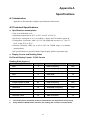
Appendix A: Specifications
Appendix B: Maintenance
4
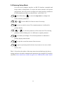
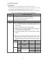
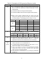
1-5. SAFETY
This meter has been designed and tested according to EN61010-1 (IEC1010-1), Safety
Requirements for Electronic Measuring Apparatus. This manual contains information and
warns which must be followed to ensure safe operation and retain the meter in safe
condition. Use of this instrument in a manner not specified herein may impair the
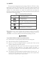
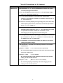
protection provided by the equipment. Some common international electrical symbols used
in this manual are shown below Table:
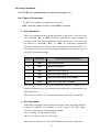
Table 1-1. International Electrical Symbols
AC - Alternating Current
DC - Direct Current
AC and DC - Alternating and Direct Current
Ground
See Explanation In The Manual
Before using the meter, read the following safety information carefully. In this manual,
"WARNING," is reserved for conditions and actions that pose hazard(s) to the user;
"CAUTION," is reserved for conditions and actions that may damage your meter.
WARNING
TO AVOID ELECTRICAL SHOCK OR OTHER INJURY:
Be sure the meter is in good operating condition and avoid working alone.
Follow all safety procedures for equipment being tested.
Inspect the test leads for damaged insulation or exposed metal. Check test lead
continuity. Damaged leads should be replaced.
This equipment operates from a power source that does not apply more than 250V
rms between the supply conductors or each supply conductor and ground. A
protective ground connection by way of the grounding conductor in the power cord is
essential for safe operation.
This equipment is grounded through the grounding conductor of the power cord. To
avoid electrical shock, plug the power cord into a properly wired receptacle before
connecting to the equipment input or output terminals.
5
To avoid explosion, do not operate this product in an explosive atmosphere.
To avoid personal injury, do not remove the cover or panel. Refer servicing to
qualified personnel.
Select the proper function for your measurement.
To avoid electrical shock, use caution when working above 60V dc or 30V ac RMS.
Disconnect the live test lead before disconnecting the common test lead.
Disconnect the power and discharge high-voltage capacitors before testing in Ω and
diode.
When making a current measurement, turn the circuit power off before connecting the
meter in the circuit.
To avoid fire hazard, always use a specified fuse.
Use clamp-on probes when measuring circuits exceeding 10 amps.
When servicing the meter, use only the replacement parts specified.
Do not allow meter to be used if it is damaged or if its safety is impaired.
The meter is safety-certified in compliance with EN61010-1 and EN61010-2-31
(IEC1010-1 & IEC1010-2-31) Installation Category ΙΙ 600V and CAT I 1000V
Pollution Degree 2. In order to maintain its insulation properties, please be sure to use
with the standard or compatible test probes.
CE requirement: Under the influence of R.F field according to standard, the supplied
test leads will pick up induced noise. To have better shielding effect, a short-twisted
lead should be used.
6
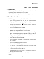
Section 2
Getting Started
2-1 Introduction
Section 2 describes the front panel operational keys, displays, input
terminals and rear panel of the meter, adjusting handle, explains general
operating features.
2-2 Getting Started
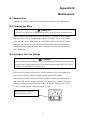
Unpacking and Inspecting the Meter
Carefully remove the meter from its shipping container and inspect it for
possible damage or missing items. If the meter is damaged or something
is missing, contact the place of purchase immediately. Save the container
and packing material in case user has to return the meter.
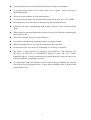
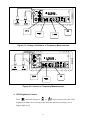
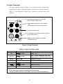
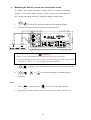
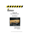
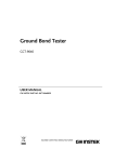
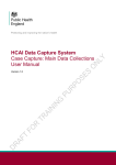
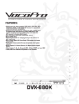
Front Panel
The front panel (shown in Figure 2-1) has three main elements: the input
terminals on the left, the primary/secondary displays, and the
pushbuttons. The pushbuttons are used to select major functions, ranging
operations, and function modifiers. These elements are described in
detail in Section 3.
mA Fuse
Receptacle
Front Panel
Protective Holster
Primary
Display
Secondary
Display
Power
Switch
POWER
Input
Terminals
Function
Buttons
Ranging
Buttons
Arithmetic
Buttons
Figure 2-1. Front Panel
7
nd
2 Display
Selection
Shift
Button
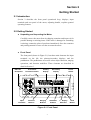
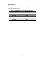
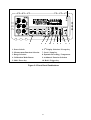
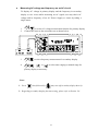
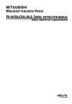
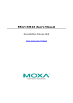
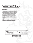
Rear Panel
The rear panel (shown in Figure 2-2) contains a line fuse, the power-line
cord connector, an RS-232 interface connector.
Line Power
Figure 2-2 illustrates the location of the Line Voltage Selector with
Fuse Holder housing. If user has already done so, plug the line cord
into the connector on the rear of the meter. The meter will operate at
any line voltage between 90Vac and 264Vac when “line voltage
selector” is set properly, and its frequency range is at 50/60Hz. For
operation safety, DO NOT APPLIES a line voltage that exceeds the
range specified to line cord connector on the rear panel of the meter.
Power-Line Cord Connector
RS-232 Connector
Earth Ground Terminal Screw
GPIB
16VA 50-60Hz
WARNING
RS-232C
~LINE VOLTAGE
FUSE
Line Voltage Selector with
Fuse Holder Housing
Line Voltage Fuse
Selection Table
Real Panel
Protective Holster
Figure 2-2. Rear Panel
CAUTION!
BEFORE TURNING THE METER ON, MAKE SURE THE LINE VOLTAGE
SELECTOR IS SET TO THE CORRECT POSITION FOR APPLIED LINE
VOLTAGE TO THE POWER-LINE CORD CONNECTOR.
8
The “line voltage selector” is settable for 100Vac, 120Vac, 220Vac,
and 240Vac line voltages.
The correct fuse ratings: 250mA fuse for 100Vac or 120Vac is selected,
and 125mA fuse for 220Vac or 240Vac is selected.
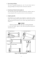
Case, Panels and Holsters
To avoid electric shock or injury, do not operate the meter without panels
or case in place.
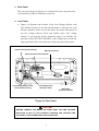
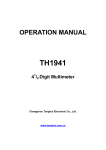
The meter is provided with special designed anti-slippery protective
holsters on the front and rear panel sides (shown in Figure 2-1 and 2-2).
The holsters provide a protection to both front and rear panels of the meter
as well as its corners. User may stack up one meter on the top of the other
without concerning the slide off of the units (shown in Picture 2-1).
The holsters can be easily removed when install the rack-mounted ears to
the meter in order to mount the meter into a 19-inch standard rack. Refer
to Section 2-7 for Rack Mounting procedures.
Picture 2-1. Stack up the Meters with Holsters
9
Grounding the Meter
The meter is grounded through power cord. To avoid electric shock or
injury, grounding wire in the power line cord must be connected.
Operating in Explosive Atmospheres
The meter does not provide explosion protection for explosive gasses or
arcing components. Do not operate the meter in such circumstances.
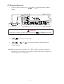
Adjusting Handle
For bench-top use, the handle can be adjusted to provide three viewing
angles. For viewing positions, pull the ends out to a hard stop (about 1/4
inch on each side) and rotate it to one of four stop positions (shown in
Figure 2-3).
WARNING
Be sure to put the meter on a table before removing the handle.
To remove the handle, adjust it to the vertical stop position and pull the
ends all the way out.
1. Viewing Position 1
4. Viewing Position 2
2. Carrying Position
5. Viewing Position 3
3. Remove Handle Position
Figure 2-3. Adjusting Handle
10
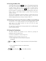
2-3 Turning the Meter ON
To turn the meter on, press the Power button to “IN” position located on the
lower right of the front panel. When the meter is turned on, the primary and
secondary displays light for about 2 seconds while an internal self-test
running by its digital circuitry. If the Hold button is pressed while the
power-up sequence is in progress, all segments and annunciators of the entire
display remain on until another button is pressed. Then the power-up
sequence continues.
After the meter completing its power-up sequence, it resumes the power-up
measurement configuration stored in non-volatile memory. The power-up
default configuration status set at factory is shown in Table 3-2.
2-4 Selecting Current Input Terminals and Measurement Range
If current (dc or ac) is being measured in the Auto-ranging mode, with a
signal input on the 500mA terminal, the meter will select the range
500µA~500mA automatically.
If a signal input is applied to the 10A input terminal, the meter
5 or 10will
amp range will
need
be selected
manually
5A orto10A
range automatically.
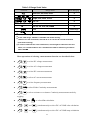
2-5 Using the Pushbuttons
The meter functions and operations can be selected by pressing the
pushbuttons on the front panel select.
A summary of pushbuttons is shown in Figure 2-4.
Pushbuttons can be used in three ways. User can:
Press a single button to select a function or operation.
EXAMPLE:
(Press)
to select AC voltage measurement for the primary display.
Press a combination of buttons, one after the other.
EXAMPLE:
then followed by
to select dBm calculation.
11
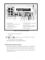
4
POWER
2
3
8
10
7
9
6
5
1
6. 2nd Display Selection / Escape key
7. Local / Setup key
8. Dynamic Recording / Comparator
9. Arithmetic Function Selection
10. Hold / Trigger key
1. Power Switch
2. Measurement Function Selection
3. Range Selection
4. Calibration Mode Button
5. Shift / Enter key
Figure 2-4. Front Panel Pushbuttons
Press multiple buttons simultaneously.
EXAMPLE:
and
simultaneously to select True RMS AC volts and DC
volts (calculated) on the primary display.
More detail operations are described in Section 3.
2-6 Basic Measurement Examples
This section describes the basic measurement procedures via operations in
front panel. These procedures as follows provide the user who wants to get a
quick start, but does not want to read the entire manual thoroughly. But it is
still recommended to read this manual thoroughly in order to fully utilize all
advantages in the meter.
12
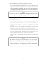
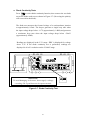
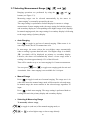
Voltage, Resistance or Frequency Measurements
Press the desired function button and connect the test leads as shown in
Figure 2-5 to measure voltage, resistance, or frequency. The meter will
select the appropriate range in the auto-range mode, and an annunciator
on the display will indicate measurement units. Note: Auto-ranging is not
available for 10A current input.
NOTE
Excessive error may occur when making measurements with 10 to 100 µV
resolutions after measuring high voltage up to 1000 volts dc. It requires
two minutes before making low-level measurements.
Current Measurements
To measure current, connect the test leads to mA input terminal or 10A
input terminal for measured current above 500mA as shown in Figure 2-6.
Be sure to turn off the power in the circuit to be measured before taking
connection.
Break the circuit on the groundside to minimize the common mode
voltage) to be measured, and place the meter in series at that point.
Turn on power to the circuit, and then read the display. The meter will
select the appropriate range automatically, and an annunciator on the
display will indicate the units of the measurement value shown.
Turn off power to the circuit and disconnect the meter from the tested
circuit.
NOTE
After making a high current measurement using the 10A input, thermal
voltages are generated that may create errors when making
high-resolution low-level dc measurements of volts, amps, or ohms.
It requires ten minutes to allow the thermals to settle out before making
low-level measurements in order to obtain the best accuracy.
13
POWER
Figure 2-5. Voltage, Resistance or Frequency Measurements
POWER
Figure 2-6. Current or Frequency Measurements
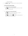
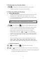
VFD Brightness Control
Press
and hold, then press
or
step by step to select the VFD
brightness to darker level (4 steps in this function and factory setting is set at
highest light level),
14
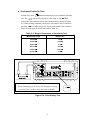
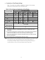
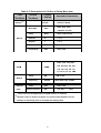
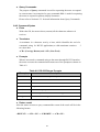
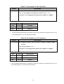
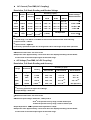
Overload Alert
The meter has provided an overload alert for voltage and current measurements.
The beeper sounds tones periodically once the measuring value is exceeded the
value shown as below Table 2-1:
Table 2-1. Beeper Responses for overload Alert Points
Measuring Function
Start Alerting Value
DC V
>1000V
AC V
>750V
DC + AC V
>750V
DC A
>10A
AC A
>10A
DC + AC A
>10A
If the input values over above points, the beeper still sounds tones whatever the
beeper has been set to OFF state, or not.
15
Diode Continuity Tests
Press
to select diode continuity function, then connect the test leads
across the diode under test as shown in Figure 2-7 (Reversing the polarity
will reverse-bias the diode).
The diode test measures the forward voltage of a semiconductor junction
at approximately 0.5mA. The beeper generates a single beep tone when
the input voltage drops below +0.7V (approximately 1.4kΩ) and generates
a continuous beep tone when the input voltage drops below +50mV
(approximately 100Ω).
Readings are displayed in the 2.3V range. “OL” is displayed for voltage
above 2.3V. If the diode continuity test is performed, readings are
displayed in 0.1mV resolution on the 2.3000V range.
POWER
WARNING!
To avoid damaging to the meter, do not apply a voltage
exceeding 500 V peak between the input terminals.
Figure 2-7. Diode Continuity Test
16
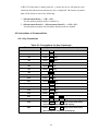
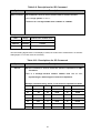
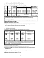
Resistance/Continuity Tests
In Ohm test, press
button momentarily to set continuity function
sign will be lit and lock the range to 500 Ω. Then
ON. The
connect the test leads and across the tested circuit as shown in Figure
2-8. While testing continuity, the beeper will sound if the resistance is
less than 10Ω. For other ranges, the beeper will sound if the resistance
falls below the typical values indicated in Table 2-2.
Table 2-2. Beeper Responses in Continuity Test
Measuring range
Beeper On
500.00 Ω
<10 Ω
5.0000 kΩ
Ω
<100 Ω
50.000 kΩ
Ω
<1 kΩ
Ω
500.00 kΩ
Ω
<10 kΩ
Ω
5.0000 MΩ
Ω
<100 kΩ
Ω
50.000 MΩ
Ω
<1 MΩ
Ω
POWER
WARNING!
To avoid damaging to the meter, do not apply a voltage
exceeding 500 V peak between the input terminals.
Figure 2-8. Ω/Continuity Test
17
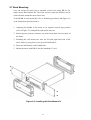
2-7 Rack Mounting
User can mount the meter into a standard 19-inch rack using RK-01 (for
single meter) Rack Mount Kit. The front and rear protective holsters can be
removed when mount the meter into a rack.
To install RK-01 rack mount kit, refer to following procedures and Figure 2-9
or the instructions provided with it:
1. Adjusting the handle of the meter to its upward vertical stop position
(refer to Figure 2-3) and pull the ends all the way out.
2. Removing two protective holsters out of the front panel and rear panel of
the meter.
3. Installing the rack mount ears onto the left and right hand side of the
meter frame by using four screws provided with RK-01.
4. Paste two blind plates on the handle hole.
5. Mount the meter with RK-01 into the standard 19” rack.
Figure 2-9. Installing the Rack Mount Kit
18
Section 3
Front Panel Operation
3-1 Introduction
This section provides a complete description of each operation that can be
performed by using the pushbuttons on the front panel.
All related information for operations and functions are grouped together.
3-2 Front Panel Operations
The following operations can be performed from the front panel:
Select a measuring function (Vdc, Vac, Adc, Aac, resistance/continuity,
frequency, and diode continuity test) for the primary display.
Base on primary display press
to select the related function for
secondary display.
Take a measurement and display a reading.
Select the manual or auto-range mode (AUTO)
Manually select a measuring range for the primary display.
Select function modifier that cause the meter to display relative readings
(REL), minimum or maximum values (MIN MAX) or decibels (dBm and
dB), or to enter the Data Hold mode or Refresh Hold (HOLD) to hold a
reading on the primary display.
Set the dB reference impedance (REFΩ).
Take a measurement and compare (COMP) it against a tolerance range
(Hi, Lo, or Pass).
Take a measurement and percentage (%) display.
Select the brightness for VFD display.
Use the ”editor” to select from option list, to enter a HI-LO range for the
compare mode and percentage mode.
Configure the computer interface (RS-232).
Send measurement directly to a printer or terminal through the RS-232
interface (RS-232 print only mode)
These and other front panel operations are described in the remainder of
Section 3.
19
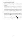
3-3 Primary and Secondary Displays
The meter is 50,000 count, Vacuum-Fluorescent dual display (VFD). This
display shows measuring readings, annunciator, and messages. The
annunciator indicates measuring units and the meter’s operating
configuration.
The dual display allows you to see two properties (e.g. Vac and frequency) of
the input signal you are measuring. The display contains two major parts,
primary display and secondary display (See figure 3-1).
The primary display contains of larger digits and annunciators and is located
on the left side of the dual display. Readings using the relative (REL),
minimum maximum (MIN MAX), data/refresh hold (HOLD), or decibels
(dBm) modifier can be shown on the primary display.
The secondary display contains of a set of smaller digits on the right side of
the dual display. To press
to turn the secondary display on and select
the related function with the primary display. Press
secondary display off or Press
then followed by
cycling to turn the
to turn off the
secondary display directly and all arithmetic functions will be disabled.
20
2
3
4
5
6
9
10
14
1
16
8
7
Primary Display
11
12
13
Secondary Display
Primary Display indications:
Secondary Display indications:
nd
1. Auto range (AUTO)
9. 2
2. Data/Refresh Hold mode (HOLD)
10. 2
3. Dynamic recording (MIN MAX)
11. Auto range (AUTO)
4. Relative mode (REL)
12. Remote state (REMOTE)
5. dBm indicator (dBm)
13. Compare function (COMP)
6. Diode/Continuity mode
14. Shift mode (S)
7. Primary Numeric data display
15. Calibration mode (CAL)
st
8. 1 Measurement unit
15
Numeric data display
nd
Measurement unit
16. Trigger mode
Figure 3-1 Dual Display Illustrations
21
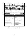
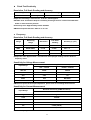
3-4 Input Terminals
The input terminals, shown in Figure 3-2 are located on the left side of the
front panel. The meter is protected against overloads up to the limits shown in
Table 3-1. Exceeding these limits poses a hazard to both the meter and
operator.
Input-High Terminal for Volts, Ohms, Hz,
Diode/Continuity Measurements
500µ
µA~500mA Range DC/AC Current Input
Terminal for DC/AC Current Measurement
Common Terminal (COM)
5A/10A Range Current Input Terminal for DC/AC
Current Measurement
500µ
µA/5mA/50mA/500mA Fuse & Holder
(1A/250V Fuse Fast)
Figure 3-2 Input Terminals
Table 3-1 Input Protection Limits
Function
Vdc
Vac, Hz
Input Terminal
Maximum Allowable Input
to COM
1200V
750V
to COM
(1)
(2)
dc
6
normal mode, or 1x10 V-Hz common mode
mA, Hz
mA to COM
500mA dc or ac rms
10A, Hz
10A to COM
10A
Ω
All functions
7
ac rms, 1100V peak, 2x10 V-Hz
(3)
dc or ac rms
to COM
500V dc or ac rms
to COM
500V dc or ac rms
Any terminal to earth
1000V dc or peak ac
(1)
In Vdc 1000V range, 1200Vdc is readable with audio warning
(2)
In Vac 750V range, 1000Vdc is readable with audio warning
(3)
10A dc or ac rms continuous, and >10A dc or ac rms for 20 seconds maximum
22
3.5 Initialization of Measurement Conditions
Power up default configuration Status:
When turning the meter on, it assumes its power-up configuration. The
power-up configuration set at the factory is shown in Table 3-2.
As configuration data for RS-232 baud rate, data bit, stop bit, parity, echo
and so on are stored in the non-volatile memory, they are not changed
when power is cycled off and on until the configurations are changed by
the user.
Table 3-2 Default configuration Status
Parameters
Default Settings
Function
DCV
Range
Auto Range
Remote/Local
Local
Data / Refresh Hold
OFF
Trigger Type
Internal
Compare mode
OFF
Percentage (%)
Relative mode
OFF
Dynamic Recording
OFF
Secondary Display mode
OFF
CAL mode
OFF
HI: 10000(10000E+0)
LO: 00000(00000E+0)
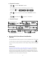
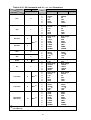
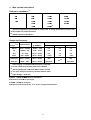
3-6 Selecting A Measurement Function
Press a function button shown in Figure 3-3, to select a measuring function.
To select ac + dc total true RMS readings, press
and
or
and
, simultaneously.
Press
toggling to turn the secondary display on and select the related
function.
The summary of ranges and scale values are shown in Table 3-3
23
4
POWER
2
1. Power Switch
2. Measurement Function Selection
3. Range Selection
4. Calibration Mode Button
5. Shift / Enter key
3
8
10
7
9
6
5
1
6. 2nd Display Selection / Escape key
7. Local / Setup key
8. Dynamic Recording / Comparator
9. Arithmetic Function Selection
10. Hold / Trigger key
Figure 3-3 Front Panel Pushbuttons
24
Table 3-3 Range Scale Value
Function
Range Scale
500mV, 5V, 50V, 500V, 1000V
,
,
,
500mV, 5V, 50V, 500V, 750V
+
,
5A, 10A
+
Hz
Ω
(1)
(4)
(2)
•
•
(3)
•
500Hz, 5kHz, 50kHz, 500kHz
•
500, 5k, 50k, 500k, 5M, 50M Ω
•
2.3V
Ω
•
500µ
µA, 5mA, 50mA, 500mA
+
,
Auto Ranging
Fixed range
500, 5k, 50k, 500k, 5M, 50M Ω (Continuity Mode)
.
(1)
In Vdc 1000V range, 1200Vdc is readable with audio warning
(2)
In Vac 750V range, 1000Vdc is readable with audio warning
(3)
10A dc or ac rms continuous, and 20A dc or ac rms for 20 seconds maximum
•
(with audio warning)
(4)
In order to eliminate the noise interference, which might be induced to the test
leads, it is recommended to use a shielded test cable for measuring resistance
above 500KΩ
Ω.
More operations of selecting a measurement function are described below:
to select DC voltage measurement
to select AC voltage measurement
to select DC current measurement
to select AC current measurement
to select frequency measurement
to select Diode Continuity measurements
to select resistance or resistance Continuity measurements mode by
toggling
then
to select dBm calculation
(
and
) simultaneously to select DC+AC RMS volts calculation
(
and
) simultaneously to select DC+AC RMS amps calculation
25
3-7 Selecting Measurement Range (
,
Ranging operations are performed by using the
and
)
,
and
buttons (see Figure 3-3).
Measuring ranges can be selected automatically by the meter in
“Auto-ranging” or manually operated by the user.
The range setting is synchronous for dual display for current or voltage
measurement. In auto ranging mode, the range setting for both the primary
and secondary display are corresponding to the higher range of two displays.
In manual ranging mode, the range setting for secondary display is following
to the range setting of primary display.
Auto-Ranging
Press
to toggle in and out of manual ranging. When meter is in
auto-range mode, the AUTO annunciator is lit.
In auto-range, the meter selects the next higher range automatically
when a reading is greater than full scale. If no higher range is available,
‘OL’ (overload) will be displayed on primary or secondary display.
Likewise, the meter will automatically selects a lower range when a
reading is less than approximately 9.5% of the full scale.
That will be another way to set Auto-ranging for Current measurement.
You can press
then
to toggle auto-ranging path for mA and
A terminals. Note: Auto ranging is not available for 10A input.
Manual Range
Press
to toggle in and out of manual ranging. The range user is in
when user enters the manual range mode will become the selected range.
In manual range, the meter remains in the selected range regardless of
input.
Press
to back auto-ranging. The range setting is performed both on
readings shown in the primary display and secondary display.
Selecting A Measuring Range
To manually select a range,
to toggle in (and out) of the manual ranging mode, or
or
to select higher range or lower range directly.
26
In manual range mode,
or
to select higher range or lower range to the desired one.
3-8 Selecting Secondary Display
To Enable the Secondary Display Mode
to turn the secondary display on and select the related
function with the primary display.
To Disable the Secondary Display Mode
cycling to turn off the secondary display ( see Table 3-6.
Descriptions for Combination of Dual Display) or
then followed by
to disable the secondary display mode.
The display remains in Primary display mode.
27
Combination of Dual Display Settings
Table 3-4 provides the available combination of inputs for the primary
display and secondary display in the dual display mode.
Table 3-4 Descriptions for Combination of Dual Display
Primary Display
Secondary Display
Step1
Step 2
Step 3
Vdc
Hz
Vac
dBm
X
(2)
Vac
Hz
Vdc
dBm
X
(2)
Vac + Vdc
Hz
Vac
Vdc
dBm
DBm
Vac
Vdc
Vac + Vdc
Adc
Hz
Aac
X
(2)
Aac
Hz
Adc
X
(2)
Aac + Adc
Hz
Aac
Adc
Vac/Aac
Aac/Vac
Hz
(1)
COMP
X
Step5
X
(2)
(2)
HI, LO, PASS
(Measuring Value)
Percentage (%)
%
(Measuring Value)
(1) a.
Step 4
The Frequency reading is corresponding to the current or voltage input signal,
respectively.
b. The frequency measurement is always working on auto-ranging mode. The Buttons
of AUTO, UP and DOWN are used to select the range of measuring signal.
c. If the current measurement is set before selecting Hz function, the step1 will show
Aac first, else show Vac.
(2)
The secondary display is blanking and the next step is step1.
Note: In DCV/A dual ACV/A, ACV/A dual DCV/A, (AC+DC) V/A dual DCV/A, (AC+DC) V/A dual
ACV/A mode, the ranges setting of both the primary and secondary display are
corresponding to the higher range of two displays (auto range mode), the ranges of
secondary display are same as the primary display (manual range mode).
28
3-9 Entering Setup Mode
User may select computer interface, set RS-232 interface (standard) and
beeper mode on Setup Mode. To ensure the remote interface will operate
appropriately, user may need to configure the remote interface parameters
by following the procedures as shown below: (refer Table 3-5)
then followed by
to enter the setup mode to configure the
remote interface parameters.
or
to select RS232 in first tier menu if necessary.
to enter second tier menu. The original parameter is indicated in
primary display.
or
to select the parameters of the menu item. The selecting
parameter will be flashing once it is different to original parameter.
to confirm your changes. The selected parameter is indicated in
primary display without flash.
to quit the second tier menu to first tier menu.
again to quit setup mode and save all parameters into non-volatile
memory then.
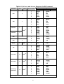
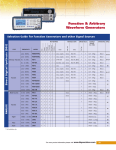
Table 3-5 describes the outline of the setup menu item and indicates the factory
settings and user selectable communication parameters for using RS-232 interface
(standard). Some menu items would not appear once GPIB interface didn’t install.
29
Table 3-5. Descriptions for Outline of Setup Menu Item
First
Second
Tier Menu
Tier Menu
Remote
Factory
Setting
(1)
RS-232
RS-232
Selectable Parameters
RS-232 or GPIB
9600, 4800, 2400,
Baud Rate
9600
Parity
None
None, Odd or Even
Data Bit
8
7 or 8
Stop Bit
1
1 or 2
ECHO
OFF
ON or OFF
Printer-Only
OFF
ON or OFF
1200,600, and 300
8000, 1200, 1000, 900,
Ref Ω
600Ω
Ω
800, 600, 500, 300, 250,
150, 135, 125, 124, 110,
93, 75, 50, 16, 8, 4, 2 Ω
Beep
ON
ON or OFF
Frequency
4096Hz
State
OFF
ON or OFF
300
100, 200, ……, 1000
Beeper
Refresh
Hold
(1)
(2)
Variation Count
(2)
4096, 2048, 1024, 8192Hz
These items will be appeared once GPIB interface is installed.
Variation count is used to recognize new value will be updated once the
variation of measuring value is exceeded the settling value.
30
3-10 Selecting Local Operation Mode
to return the operation control priority from remote mode
(computer controlled) to local mode (user controlled).
3-11 Operating Arithmetic Functions
Using dBm Modifier
The dBm measurement is used for decibel conversion of power per 1mW
consumption into a 600Ω load and can be applied to Vdc, Vac and
Vdc+Vac measurements only. Voltage measurement is converted to dBm
by using the following formula:
dBm = 10x log10 [1000 x (measuring value)2 /reference
then followed by
to toggle in (and out) dBm modifier mode
The meter will displays the dBm modifier on the primary display and the
reference impedance will be indicated and flashed on the secondary
display within 3 seconds. The default value by factory is 600Ω.
In dBm modifier mode, press
and
to select the different
impedance desired, the reference impedance will be indicated and flashed
on the secondary display within 3 seconds. The new setting value will be
kept until power off.
Any of the following 21 types of reference impedance may be selected:
8000Ω, 1200Ω, 1000Ω, 900Ω, 800Ω, 600Ω, 500Ω, 300Ω, 250Ω,
150Ω, 135Ω, 125Ω, 124Ω, 110Ω, 93Ω, 75Ω, 50Ω, 16Ω, 8Ω, 4Ω, 2Ω
Operation procedures:
then followed by
or
to enter dBm calculation mode.
to scroll to the desired impedance value shown as the following
operation example. The secondary display will indicate the measuring value
of voltage after finished impedance selection.
31
• Operation Example:
Using MIN.MAX Modifier for Dynamic Recording
“MIN MAX” modifier enables the meter to store the minimum and
the maximum input signals measured and elapsed time the value recorded
since the “MIN MAX” modifier was selected. The definitions of “MIN”
and “MAX” are defined as follows:
MIN: Minimum value of calculation results for measured signal
MAX: Maximum value of calculation results for measured signal
If “MAX” modifier is selected, the display indicates the latest maximum
reading and elapsed time accordingly until next measurement reading exceeds
the previous recorded reading.
If “MIN” modifier is selected, the display indicates the latest minimum reading
and elapsed time accordingly until next measurement reading drops below the
previous recorded reading.
If “MIN MAX” mode is selected, the display indicates the actual value of input
signal. Selecting this modifier in auto range, it will record the value of MAX,
MIN for different ranges.
The elapsed time is recorded since the modifier has been selected. The
elapsed time is shown on the secondary display with “HH.MM.SS”. The HH is
0~19 hours, MM is 0~59 minutes and SS is 0~59 seconds. The display will
“ once over the maximum time of “19.59.59”.
indicate with “
Note: If the beep mode is set to “ON”, the beeper will emit a single tone when
an effective maximum or minimum value is recorded.
32
Operation Procedures
to enable “MIN.MAX” modifier.
The recording mode will rotate as the following sequences if keep
pressing the
key: Min.Max
Max
Min
Min.Max
for more than one second to disable “MIN MAX” modifier.
Or
then followed by
to turn off all modifiers.
Operation Example
Selecting HOLD (Data /Refresh Hold) Modifier
Date Hold
The data hold function allows operators to freeze the displayed value. This feature
is useful when user wants to keep the measuring reading, user may press
to
freeze the primary display and then read the display reading without loosing the
reading.
Refresh Hold
You can select Refresh Hold to replace Data Hold at setup mode. The Refresh
Hold allows you to take measurement in dangerous or difficult measuring field
and you can’t look at the display. This function will update hold value with new
measuring value automatically, and sound a tone to remind user. The operation of
push button is same as the operations of Data hold.
33
Press
to enter Refresh Hold mode. The present value will be held and the
“HOLD ” will be lit. It will be ready to hold new measuring value once the
variation of measuring value exceed the setting of variation count, and the
“HOLD ” will be flashed. The hold value will be updated until the measuring
value is stable, then stop flash and light “HOLD ” and sound a tone to remind
user.
For voltage and current measurements, the holding value will not be updated
when the reading below 500 counts. For resistance and diode measurements,
the holding value will not be updated if the reading at “OL” or open state. The
holding value may not be updated once the reading can’t reach stable state for
all measurements.
Operation Procedures
to enable Data Hold mode, and the annunciator HOLD will be
shown on the primary display.
again to disable Data Hold mode.
Note: The Data Hold mode can be used for other arithmetic functions such as
dBm, REL and Min / Max.
Selecting REL (Relative) Modifier
The relative function subtracts a stored value from the primary display and
indicates the result. This function is used for primary display only.
Press
momentarily to set the relative mode. This sets the display
to zero and stores the displayed reading as a reference value. The "REL"
will be lit also. Both ranges of auto or manual can set relative mode. The
relative mode can’t set when an overload has occurred. If the relative mode
is set in auto-ranging condition, enable the COMP or Percentage function
will clear the relative mode. You do need to set relative function again.
Press
again to exit the relative mode.
34
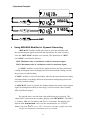
Using COMP (Compare) Function
“COMP” function compares the measurement inputs with the pre-set HI
and LO limits. The compare function calculation expression is based on
counts without decimal point.
HI:
Measurement value > High (HI) limit value
LO:
Measurement value < Low (LO) limit value
PASS: High limit value ≥ Measurement value ≥ Low limit value
When “COMP” function is enabled, the actual measuring value will be
shown in primary display and a comparison result “HI”, “LO”, or “PASS”
will be shown in secondary display.
The beeper will sound three tones as the result is changed from “PASS” to
“HI” or “LO”, and one tone from “HI” or “LO” to “PASS”.
Notes:
1. The Compare function can be used with other arithmetic functions such as
REL, MINMAX, and dBm modifiers
2. For frequency measurement, it will be locked to the range user is in when user
enters this mode will become the selected range.
Operation Procedures
then followed by
to enable the “COMP” function.
then followed by
again to disable the “COMP” function.
Setting a Compare Limit / Percentage Value
Using the following procedure to set the HI and the LO limit values for
“COMP” / “Percentage” function:
then followed by
to enter the HI limit setup mode.
The HI limit will be shown in primary display.
,
,
or
to change this value.
to store the HI limit value in counts.
then followed by
and repeat the above steps to set and store
35
the LO limit value.
Note: 1. After set the Hi and/or the LO limits, the limits can be used for all ranges.
However, at different range, the HI and the LO limits represent different
values according to their respective counts.
The RIGHT and LEFT button is used to select which digit will be adjusted.
Push the buttons to left shift or right shift five digits.
D5 D4 D3 D2 D1
D5 D4 D3 D2 D1
The UP and DOWN button is used to adjust the value, press UP or down
button to increase or decrease one count for each digit, respectively. For the
most significant digit (D5), its digital variation is shown as following:
-50000 -40000 …
00000 10000 … 50000
Press UP button again to 60000, then the setting value will be
subtracted 50000 automatically.
36
-50000 -40000 … -10000 00000 … 50000
Press DOWN button again to -60000, then the setting value will
be subtracted -50000 automatically.
For digits of D4 to D1, these digits can be adjusted from –9~9 by pressing
UP and down buttons. Once the value of D5 has been set to 5 or -5, any
adjustment to other digits will cause the setting value to subtract 50000 or
-50000 automatic, respectively.
Press SHIFT button to store the settling value and exit this mode. Once the settling
value is conflicted with other limits, the current settling will be replaced with LO
limit or HI limit, respectively. For example, to store HI limit of 30000 but LO limit
was 40000. The settling value will be replaced with LO limit of 40000, and the
beeper sounds three tones to alert user to set HI limit again. It doesn’t quit settling
mode in this situation.
Using Percentage (%) Function
To transfer the measuring value with a proportional percentage (%) display.
For example, transfer the current of 4-20 mA to 0%~100% display for
transmitter. It is based on the settling value of HI and LO limits (same as
compare function) and according to following formula to calculate
Percentage (%)= [Measuring value – LO/(HI-LO)] x100%
If HI limit is equal to LO limit, the formula is change to as below:
Percentage (%)= [(Measuring value-HI)/HI] x100%
For example, transfer the current of 4-20 mA to 0%~100% display for
transmitter. You should set LO limit to 4,000 counts and HI limit to 20,000
counts and measure in the range of 50mA.
Press
then followed by
to enter percentage function. The actual
measuring value will be shown in primary display and the secondary display
will indicate calculation result for percentage (%). An “OL” will be indicated
37
once over the maximum display of 999.99 %. This function will be used for
lock range. If select this function during auto-ranging, it will lock to existing
range. Press
then followed by
to exit percentage function
.
Notes:
1. The Auto-ranging Relative mode or auto-ranging dynamic record will be closed
when percentage function is set. For relative or dynamic record function should
be selected again if necessary.
2. For frequency measurement, it will be locked to the range user is in when user
enters this mode will become the selected range.
3-12 Selecting Trigger mode
This meter has two types of trigger mode. One is internal to continuous update
reading, and the other one is external control by bus or front panel. The default
trigger mode is internal after the power up.
The external trigger is used with delay settling has been set by meter automatically. The
amount of trigger delay varies depending on different function.
When external trigger is enabled, the meter determines the ranges for the primary
display based on the input at that time. The meter is then ready to begin measuring the
input on the optimum range as soon as the trigger is received. If the input changes so
that either display auto ranges after the trigger is received, the auto ranging response
times may be required before each measuring result is displayed.
The meter takes measurements when it is triggered to do so. The two trigger types
available on the meter fall into two basic categories:
An "internal trigger" triggers measurements continuously.
An "external trigger" triggers a measurement only at the direction of the user.
A measurement can be externally triggered in three ways:
1.
Front panel by TRIG key.
2.
RS-232 interface. Please refer to chapter 6 for TGS<n> and TGM<n>.
3.
GPIB interface. Please refer to chapter 7 for related commands.
38
Operation Procedures for Front Panel
To enable an external trigger and trigger a measurement from the front panel,
perform the following procedures:
1. Press
then followed by
to enter trigger mode and standby
condition. The annunicator of TRIG will be lit, and display is indicated
with “
”.
2. Press
to get a new value. After a measuring, then the result will be
indicated and held on display.
3. Press
4. Press
to get a new value again.
,
or
to select auto-ranging or manual range as
necessary.
5. Press other function keys to select what you want.
6. Press
then followed by
to disable external trigger.
Notes:
1.
When external trigger is enabled, all the arithmetic functions will be
disabled.
2.
Press
3.
The trigger mode will disable the secondary display except frequency
then followed by
may disable external trigger also.
function in primary display.
39
Section 4
Measurement Application Examples
4-1 Introduction
Section 4 describes some advanced features and applications that help the
user to operate the meter more effectively. The user must be familiar with the
basic measurement operations described in Section 2 and Section 3 and has a
basic understanding of electronics knowledge.
4-2 Applications for Using Dual Display
The dual display capability is one of the most useful features provided with
the meter. User may take the advantages to greatly enhance the test and
measurement capabilities.
Some common combinations and applications of using dual display are
provided in Table 4-1.
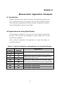
Table 4-1. Typical Combinations and Applications for Using Dual Display
Primary
Display
Secondary
Display
Vdc
Vac
• Testing DC to AC or AC to DC converter circuit
Vac+Vdc
Vdc
• Measuring DC level and AC ripple of power supply
Vac
Hz
• Measuring AC frequency response of amplifier circuit
Aac
Hz
• Adjusting AC motor control
Adc
Aac
• Measuring AC ripple and DC current of power supply
Aac+Adc
Adc
• Measuring current dissipation for power supply analysis
dBm
Reference Ω
dBm
Vdc
• Indicating DC voltage and dBm
dBm
Vac
• Indicating AC voltage and dBm
Applications
• Setting dB reference impedance and show dBm
40
4-2-1 Dual Display Operation Examples
This section will describe some practical operations of using dual display
features.
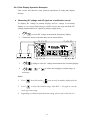
Measuring DC voltage and AC ripple on a rectification circuit.
To display DC voltage in primary display, and AC voltage in secondary
display or vise versus while testing a rectifier circuit, user may check the DC
voltage supplied and its AC ripples by taking a single meter.
1.
to select DC voltage measurement for primary display.
2. Connect the meter to the unit under test as shown below:
POWER
3.
cycling to select AC voltage measurement for secondary display.
4.
,
or
to select auto-ranging or manual range as
necessary.
Notes:
1.
Press
then followed by
2.
Press
to select the suitable range, if the DCV + AC ripple is over the
may turn off secondary display directly.
scale of present range.
3.
Regarding secondary display function setting, please refer to Section 3-6.
41
Measuring AC and DC current on a rectification circuit.
To display AC current in primary display and DC current in secondary
display or vise versus while testing a rectifier circuit, user may check the
DC current component and its AC ripples by taking a single meter.
1.
2.
to select DC current measurement for primary display
Connect the meter to the unit under test as shown below:
POWER
WARNING!
1. Select a correct input terminal according to the input range to be used.
2. To avoid damaging the meter do not apply current exceeding specified range to input
terminals of ” mA” or “A” (see the appendix A Specifications).
3.
cycling to select AC current measurement for secondary display.
4.
,
or
to select auto-ranging or manual range as
necessary.
Notes:
1.
Press
then followed by
may turn off secondary display.
2.
Regarding secondary display function setting, please refer to Section 3-6.
42
Measuring AC voltage and frequency on an AC circuit.
To display AC voltage in primary display and the frequency in secondary
display or vise versus while measuring an AC signal, user may check AC
voltage and its frequency of an AC Power Supply or circuit by taking a
single meter.
to select AC voltage measurement function for primary display.
1.
2.
Connect the meter to the unit under test as shown below:
POWER
3.
to select frequency measurement for secondary display.
4.
,
or
to select auto-ranging or manual range for
primary display as necessary.
Notes:
1. Press
then followed by
may turn off secondary display directly.
2. Regarding secondary display function setting, please refer to Section 3-6.
43
4-3 Measuring Resistance
and COM input terminals as shown
1. Connect a resistor under test to
below:
POWER
WARNING!
Do not apply a voltage exceeding 500 V peak between
2.
to select Ω measurement.
3.
,
or
and COM input terminals.
to select auto-ranging or manual range for
primary display.
Note: When measuring low resistance, use “REL” modifier function to reduce the
measuring error created by the test leads resistance and contact resistance in
the test loop (0.1Ω ~ 0.5Ω typical).
44
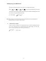
4-4 Measuring True RMS AC+DC
The meter can measure the true rms value of ac voltages and currents.
When
and
or
and
are pressed simultaneously, the meter
will measure the dc and ac signals alternatively then calculate and display the ac+dc
rms value by using the following formula:
(AC+DC) RMS =
dc 2 + ac 2
Note: When voltage (ac+dc) measurement function is selected, the Vdc input impedance is
paralleled with an ac-coupled 1.1MΩ ac divider.
Measurement example:
To take a true rms voltage ac+dc measurement on an ac signal, assuming the input
ac is 0.1Vrms 1kHz sine wave ac signal and with a dc offset voltage +4.5 volts, the
meter will read and display the results approximately as:
4.5 2 + 0.12 ≒ 4.5011 volts
45
Section 5
Calibrating the Meter
5-1 Introduction
CAUTION!
TO AVOID DAMAGING THE DEFAULT CALIBRATION DATA STORED IN A
NON-VOLATILE MEMORY, A CALIBRATION TO THE METER CAN ONLY BE
DONE BY AN AUTHORIZED SERVICE CENTER AND QUALIFIED PERSONNEL
WITH APPROPRIATE EQUIPMENT.
THE WARRANTY WILL BE EXPIRED IF THE SEALED LABEL ON THE CAL
BUTTON OF THE FRONT PANEL IS BROKEN.
FORE DETAIL INFORMATION ABOUT CALIBRATION PROCEDURES, PLEASE
CONTACT FACTORY OR AUTHORIZED DISTRIBUTOR.
It is recommended to recalibrate and verify the meter at least once a year to
ensure it meets the original designed performance and specifications.
The meter is designed with closed-case calibration capability (no internal
adjustment). To enter calibration mode by pressing the CAL button located in
the hole on the upper right position of the front panel display screen.
The meter can be calibrated and verified by keystrokes via the front panel or
through RS-232 interface command with appropriate equipment and qualified
personnel only.
5-2 Environmental Condition
Calibration or verification test should be performed under laboratory
condition which ambient temperature/ relative humidity can be controlled.
5-3 Warm up
Allow up to at least 60 minutes warm-up time before performing calibration
or a verification test to the meter. After exposure or storage in a high humidity
(condensing) environment, 2 hours warm-up time is essentially required.
46
5-4 Recommended Test Equipment
The test equipment requirements listed in Table 5-1 or equivalents are
required to perform the calibration and performance verification test
procedures. Alternative equipment may be used as long as the accuracy is at
least as good as those listed.
Table 5-1 Standard Equipment Requirements
Standard
Source
Operating
Range
Accuracy
Required
Recommended
Equipment
DC Voltage
Calibrator
Range, 0 to 1000VDC
≤ ± 0.002%
Fluke 5520A or
equivalent
AC Voltage
Calibrator
Range, 0 to 750V, 1kHz
≤ ± 0.03%
Fluke 5520A or
equivalent
DC Current
Calibrator
10mA to 100mA
≤ ± 0.01%
1A to 10A
≤ ± 0.03%
AC Current
Calibrator
10mA to 1000mA, 1kHz
≤ ± 0.1%
1A to 10A, 1kHz
≤ ± 0.2 %
450Ω
Ω, 4.5kΩ
Ω, 45kΩ
Ω,
450kΩ
Ω, 4.5MΩ
Ω
≤ ± 0.01%
Fluke 5520A or
equivalent
30MΩ
Ω
≤ ± 0.05%
Fluke 5520A or
equivalent
2V/4500Hz
≤ ± 0.005%
Fluke 5520A or
equivalent
Resistance
Calibrator
Audio Level
Generator
47
Fluke 5520A or
equivalent
Fluke5520A or
equivalent
Section 6
RS-232 Remote Operation
6-1 Introduction
Section 6 describes how to operate the meter via standard RS-232 interface. It
also explains the detail information of all RS-232 interface command sets used
in the meter. The remote control operation enables the user either to manually
operate the meter via a t erminal or ex ecutes a host computer program
automatically.
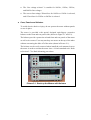
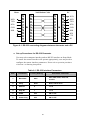
6-2 RS-232 Interface Overview
The port serial contains of D-t ype 9-pin male connector on r ear panel of the
meter is used to communicate the meter with a host computer, or terminal via
RS-232 standard inter face. Figure 6-1 shows th e RS-232 conne cting diagram
between the meter and a host computer.
RS-232 interface is a serial binary data interchange, which operates from 300 to
9600 baud rate and the distance b etween any two RS-232 interf ace can be
extended up to 50 feet. RS-232 port of the met er is desi gned in full duplex,
which makes the meter more reliable and efficient in data taking.
6-3 RS-232 Interface Parameters Set up
In order to operate the meter via a host computer or terminal, the parameters in RS-232
interface within the meter has to match the parameters in the serial interface provided
by the host or terminal.
The following procedures will guide the user to set up RS-232 inter face parameters
within the meter to comply RS-232 interface with the host. The default settings of the
meter at factory are 9600-baud rate, non-parity, 8 data bits, and 1 stop bit (9600, n, 8,
1).
Table 6-1 indicates the factory settings and user selectable communication parameters
by using RS-232 interface.
49
Meter
PC
Null Modem Cable
1
1
1
1
DCD
RXD
2
2
2
2
RXD
TXD
3
3
3
3
TXD
DTR
4
4
4
4
DTR
GND
5
5
5
5
GND
DSR
6
6
6
6
DSR
7
7
7
7
RTS
8
8
8
8
CTS
9
9
9
9
RI
Figure 6-1. RS-232 connecting diagrams between the meter and a PC
!
Set up Procedures for RS-232 Parameter
User may select computer interface and set RS-232 interface on Setup Mode.
To ensure the remote interface will operate appropriately, user may need to
configure the remote interface parameters. Please refer to operation procedures
of Section 3-10 Entering Setup Mode.
Table 6-1. RS-232 Interface Parameters
Item
Parameter
Factory Setting
Selectable Parameter
1
Baud Rate
9600
2
Parity
None
None, Odd or Even
3
Data Bit
8
7 or 8
4
Stop Bit
1
1 or 2
5
ECHO
OFF
ON or OFF
6
Printer-Only
OFF
ON or OFF
9600, 4800, 2400, 1200, 600,
and 300
50
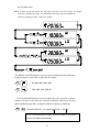
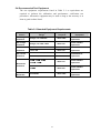
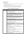
6-4 Using Commands
Note: All RS-232 commands must be entered in the upper case.
6-4-1 Types of Commands
The RS-232 commands are grouped in three types:
KEY commands, SET commands, and QUERY commands.
!
Key Commands
There are 16 pushbutton keys on the front panel of the meter. User may use the
Key commands <K1> to <K16> for directly simulating a single keystroke by
pressing on the front panel push button via RS-232 interfa ce. User may also
use other Ke y commands <K17> to <K20> for simulating combination
keystroke functions (see complete Key commands description on Table 6-3).
For example, user may use the following command sets to select the meter at
Vdc 120V measurement range.
Step
Command
Equivalent Keystroke Response
1
<K1>
Select Vdc function
2
<K9>
Select one range up
3
<K9>
Select one more range up
4
<K9>
Select one more range up
5
<K9>
Select one more range up at 1000Vdc
6
<K10>
Select one range down to 120Vdc
This above op erations will be more complicated and time consumin g, but it
would be conveni ent for special applic ations and make a virtual instrum ent
application easier.
Please refer to Section 6-5-1 for detail information about Key Commands.
!
Set Commands
Unlike Key commends, Set command controls the meter operations through
a string of commands. For example, to set the meter at Vdc 120 V range,
user may only need one command string <S104>:
<S> for setting, <1> for primary display,
<0> for Vdc function, <4> for 120V range.
Please refer to Section 6-5-2 for detail information about Set Commands.
51
!
Query Commands
The purpose of Query commands is used for requesting the meter to respond
its current status. An example of a query command <R1> is used for requesting
the meter to respond its primary display characters.
Please refer to Section 6-5-3 for detail information about Query Commands.
6-4-2 Command Syntax
!
Echo
With echo ON, the meter echoes (returns) all the characters whatever it
receives.
!
Terminator
A terminator is a character sent by a host, w hich identifies the end of a
command string. In RS-232 applications, a valid terminator consists o
f
two-byte data:
<CR> (Carriage Return) and <LF> (Line Feed)
!
Prompts
When a host sends a command string to the meter through RS-232 interface,
the meter executes the command and returns one of the prompts as shown on
Table 6-2.
Table 6-2. RS-232 Return Prompts
Prompts
>
Description
The meter is reset to power-up initialisation status.
=>
A command is executed and no errors are detected.
!>
A command error is detected.
?>
A parameter error is detected.
#>
The local key is pressed.
S>
The set up function is under executing.
@>
No numeric reading is available.
Return result
After the meter executes a query command the return of the result will be in the
following format:
!
<RESULT> + <CR> <LF> + <PROMPT> + <CR><LF>
52
If RS-232 of the meter is under print-onl y mode, the me ter will print ou t the
measured data when the measurement cycle is completed. The format of printed
data will be shown as one of the following:
1. <Measurement Data> + <CR> <LF>
for only primary display mode is enabled, or
2. <Measurement Data #1>, <Measurement Data #2> + <CR> <LF>
for both primary display and secondary display mode are enabled
6-5 Instructions of Command Sets
6-5-1 Key Commands
Table 6-3. Descriptions for Key Commands
Command
Equivalent Keystroke on the front panel
K1
Press
Vdc
key
K2
Press
Adc
key
K3
Press
Vac
key
K4
Press
Aac
key
K5
Press
Ω
K6
Press Diode key
K7
Press
K8
Press AUTO key
K9
Press
key
K10
Press
key
K11
Press MinMax key
K12
Press
Hold
key
K14
Press
REL
key
K15
Press
Shift
key
K16
Press
2nd
key.
K17
Press
Vdc
and
Vac
keys simultaneously
K18
Press
Adc
and
Aac
keys simultaneously
K19
Press
Shift
key
Hz
key
then
keys on the front panel.
(Increasing the intensity of VFD display)
K20
Press
Shift
then
keys on the front panel.
(Decreasing the intensity of VFD display)
53
6-5-2 Set Commands
!
S1 command
The S1 command is used to set up the measurement functions, ranges, and reading rates
for the primary display in the meter.
The S1 command is followed by three parameters <f>, <r>, and <x> in order.
All characters for the <f>, <r>, and <x> parameters must be in the upper case.
For detail information of using the S1 command, see Table 6-4 and Table 6-6.
Table 6-4. Descriptions for S1 Command
Syntax
S1<f><r><x>
Description
In S1 command, <f>, <r>, and <x> parameters are used to set up the
primary display measurements:
<f> for specifying Measurement functions, <r> for specifying ranges,
and <x> for specifying reading rate.
<f> is a necessary parameter for specifying the measurement
functions. <f> parameter is defined by a numeric value from “0” to
“9” and character “A”.
<r> is an optional parameter for specifying measurement range. <r>
parameter is defined by a numeric value from “0” to “7”. If <r>
parameter is omitted (<x> parameter should be omitted, too.) The
meter will be set at auto-ranging.
<x> is an optional parameter for specifying a reading rate. It is defined
by a character “S”, “M”, or “F”, in which “S” is for slow rate, “M”
for medium rate, and “F” for fast rate
If <x> parameter is not specified, the meter will remain on its current
reading rate without change.
Table 6-6 shows all available S1 command parameters and available
combinations.
Example 1: “S104S”
(<f>, <r> and <x> are all specified)
Set primary display of the meter to DCV 120V with manual range
and at slow reading rate.
Example 2: “S142”
(<x> is omitted)
Set primary display to DCA 120mA with manual range, and the
reading rate will not be affected.
Example 3: “S17”
(Both <r> and <x> are omitted)
Set primary display to frequency with auto ranging and the reading
rate will not be affected.
54
Table 6-5. Descriptions for S2 Command
Command
S2<f><r><x>
Description
In S2 command, <f>, <r>, and <x> parameters are used to set up the
secondary display measurements:
<f> for specifying Measurement functions, <r> for specifying ranges,
and <x> for specifying reading rate.
<f> is a necessary parameter for specifying the measurement
functions. <f> parameter is defined by a numeric value from “0” to
“9” and character “A”.
Because the secondary display can only display DCV, ACV, DCA, ACA,
and Frequency (Hz) functions, therefore, the available parameters
are “0”, “1”, “4”, “5” and “7”.
<r> is an optional parameter for specifying measurement range. The
parameter value can be from “0” to “7”. If <r> parameter is omitted,
<x> parameter should be omitted, too. The meter is set to
auto-ranging and will stay at the current reading rate.
<x> is an optional parameter for specifying a reading rate. It is defined
by a character “S”, “M”, or “F”, in which “S” is for slow rate, “M”
for medium rate, and “F” for fast rate
If <x> parameter is not specified, the meter will remain on its current
reading rate without change.
Table 6-6 shows all available S2 command parameters and available
combinations.
Example 1: “S204S”
(<f>, <r> and <x> are all specified)
Set secondary display of the meter to DCV 120V with manual range
and at slow reading rate.
Example 2: “S242”
(<x> is omitted)
Set secondary display to DCA 120mA with manual range and the
reading rate will not be affected.
Example 3: “S27”
(Both <r> and <x> are omitted)
Set secondary display to frequency with auto-ranging and the
reading rate will not be affected.
55
Table 6-6 S1, S2 Commands and <f>, <r>, <x> Parameters
Parameter
S1
Vdc
Vac
S (Slow)
0
Auto range
400mV
4V
40V
400V
1000V
1
0
1
2
3
4
5
Auto range
120mV
1.2V
12V
120V
750V
Auto range
400mV
4V
40V
400V
750V
0
1
2
3
4
5
6
7
Auto range
120Ω
1.2kΩ
12kΩ
120kΩ
1.2MΩ
12MΩ
120MΩ
Auto range
400Ω
4kΩ
40kΩ
400kΩ
4MΩ
40MΩ
300MΩ
0
1
2
3
4
0
1
0
1
2
3
4
Auto range
12mA
120mA
(2)
1.2A
12A
Auto range
1.2V
Auto range
1200Hz
12kHz
120kHz
1MHz
Auto range
40mA
120mA
(2)
1.2A
12A
Auto range
2.5V
Auto range
1200Hz
12kHz
120kHz
1MHz
0
1
2
3
4
5
Auto range
120mV
1.2V
12V
120V
750V
Auto range
400mV
4V
40V
400V
750V
0
1
2
3
4
Auto range
12mA
120mA
(2)
1.2A
12A
Auto range
40mA
120mA
(2)
1.2A
12A
0
1
2
3
4
5
6
7
120Ω
120Ω
1.2kΩ
12kΩ
120kΩ
1.2MΩ
12MΩ
120MΩ
400Ω
400Ω
4kΩ
40kΩ
400kΩ
4MΩ
40MΩ
300MΩ
2
4
Aac
5
V (ac+dc)
A (ac+dc)
Continuity
(Ω/2-wire)
(1)
(2)
(1)
3
6
Hz
N/A
(1)
7
8
9
A
F (Fast)
Auto range
120mV
1.2V
12V
120V
1000V
Adc
Diode
M (Medium)
0
1
2
3
4
5
N/A
Ω/4-wire
<x> =
<r>
<f>
Function
Ω/2-wire
S2
N/A
N/A
N/A
(1)
(1)
(1)
Not Applicable
For 5492 only
56
Table 6-7. Descriptions for SH Command
Syntax
Description
SH<s><nnnnnn>
SH command is used to set high limit in counts for compare function.
<s> is a sign symbol for the high limit, can be set as “+” or “-“.
<nnnnnn> is a six-digit decimal number from “000000” to “199999”.
Example: “SH+102345”
Rate
Range
High limit to be
Slow
120.000 V
+102.345V
Medium
400.00V
+1023.45V
Fast *1
400.0V
+1023.4 V
Notes:
1.
The least setting digit is blank on the display of meter, but it still uses to compare function. To set
least setting digit to “0” for fast mode as necessary.
Table 6-8. Descriptions for SL Command
Syntax
Description
SL<s><nnnnnn>
SL command is used to set the low limit in counts for compare (COMP)
function.
<s> is a sign symbol “+” or “-“.
<nnnnnn> is a six-digit decimal number from “000000” to “199999”.
Example: “SL-098765”
Rate
Range
Low limit to be
Slow
120.000 V
- 98.765V
Medium
400.00V
- 987.65V
Fast *1
400.0V
- 987.6 V
Notes:
1. The least setting digit is blank on the display of meter, but it still uses to compare function. To set
least setting digit to “0” for fast mode as necessary.
57
Table 6-9. Descriptions for SR Command
Syntax
Description
SR<s><nnnnnn>
SR command is used to set the relative base for relative function.
<s> is a sign symbol “+” or “-“.
<nnnnnn> is a six-digit number from “000000” to “199999”.
Example: “SR+001000”
Rate
Range
Relative base modifier to be
Slow
120.000 V
+1.000V
Medium
400.00V
+10.00V
Fast *1
400.0V
+10.0 V
Notes:
The least setting digit is blank on the display of meter, but it still uses to relative base. To set least
setting digit to “0” for fast mode as necessary.
Table 6-10. Descriptions for SO Command
Syntax
Description
SO<nn>
SO<nn> command is used to select the reference impedance for dBm
calculation.
<nn> is a two-digit decimal numeric number from “00” to “20”,
representing 21 different types of reference impedance.
Example: Command string “SO15” to set reference impedance at 600Ω.
nn
Impedance
nn
Impedance
nn
Impedance
00
2Ω
07
110Ω
14
500Ω
01
4Ω
08
124Ω
15
600Ω
02
8Ω
09
125Ω
16
800Ω
03
16Ω
10
135Ω
17
900Ω
04
50Ω
11
150Ω
18
1000Ω
05
75Ω
12
250Ω
19
1200Ω
06
93Ω
13
300Ω
20
8000Ω
58
6-5-3 Query Commands
!
R0 command
R0 command is used for requesting the meter to return its current status.
The meter will then respond the followin g 10-digit character string to t he host after
receiving the R0 command: <h1h2><g1g2><v><x><f1><r1><f1><r1>
For detail information of using R0 command, please refer to Table 6-11 and Table 6-12.
Table 6-11. Descriptions for R0 Command and Response
Syntax
R0
Response Description
R0 command is used to read the status of the meter.
The meter will respond the following character string:
<h1h2><g1g2><v><x><f1><r1><f2><r2>
Response
Description
<h1h2>
<h1h2> is a two-digit hex number; each digit contains 4-bit binary codes
(Bit 7-4 and Bit 3-0 respectively) to represent eight types of status
about the meter.
<h1> and <h2> representations are described as follows.
<h1> indicates the results of compare (COMP) function and whether the
meter is operating in a dual display mode;
<h2> represents the ON/OFF status for other four types of arithmetic
function.
Example: If <h1h2> contains a character string “A8”, convert it to an
8-bit binary format “10101000” that means the meter is in Dual
display mode, compare function is ON, and the result of compare is
Pass.
<h1h2>
<h1>
<h2>
Bit
Status
0
1
7
Compare mode
off
on
6
Relative mode
off
on
5
dB mode
off
on
4
dBm mode
off
on
3
Display Mode
Single
Dual
x
Hi
x
Pass
x
Lo
2
1
Compare Result
0
59
Table 6-11. Descriptions for R0 Command and Response (cont’d)
Response
Description
<g1g2>
<g1g2> is a two-digit hex number; each digit contains 4-bit binary codes
(Bit 7-4 and Bit 3-0) respectively to represent eight types of status
about the meter.
<g1> indicates the status for four types of meter operation;
<g2> indicates the ON/OFF status for other four types of meter operation,
Example: If <h1h2> contains a character string “18”, convert it to an 8-bit
binary code “00011000” that means the meter is under Auto-ranging
st
for Primary Display (1 Auto-Ranging) and the reading is on hold.
<g1g2>
<g1>
Bit
Status
0
1
7
CAL Mode
off
on
6
2nd Function
off
on
5
Shift Key
off
on
Hold Reading
off
on
off
on
off
on
4
3
2
<g2>
<v>
st
1 Auto-Ranging
nd
2
Auto-Ranging
1
MIN Recording
off
on
0
MAX Recording
off
on
<v> is a single numeric numbers “0”, “1”, “2”, or “3” used for representing
the intensity level of VFD display on the meter.
<x>
<v>
0
1
2
3
Intensity Level
50%
60%
75%
100%
<x> indicates the status of reading rate of the meter. This character may
contain one of three different characters “S,M, or F”, in which “S”
represents for slow rate, “M” for medium rate, and “F” for fast rate.
<f1><r1>
and
<f2><r2>
<f1> indicates the measurement function in primary display. It contains
numeric value from “0” to “9” and character “A”.
<r1> is primary display measurement range The value is from “1” to “7”.
Please refer to Table 6-11 for an available value.
<f2> and <r2> are similar to <f1> and <r1> but representing the secondary
display status instead. If the meter is operated under single display
mode, <f2> and <r2> will not be returned.
For detail information of interpreting the < f1><r1> and <f2><r2>, please refer
to Table 6-12.
60
Table 6-12 <f1><r1> and <f2><r2> Response for R0 Command
Function
<f1>=
Vdc
Vac
Ω/2-wire
<f2>=
0
400mV
4V
40V
400V
1000V
1
1
2
3
4
5
120mV
1.2V
12V
120V
750V
400mV
4V
40V
400V
750V
1
2
3
4
5
6
7
120Ω
1.2kΩ
12kΩ
120kΩ
1.2MΩ
12MΩ
120MΩ
400Ω
4kΩ
40kΩ
400kΩ
4MΩ
40MΩ
300MΩ
1
2
3
4
12mA
120mA
(2)
1.2A
12A
40mA
120mA
(2)
1.2A
12A
1
1.2V
2.5V
1
2
3
4
1200Hz
12kHz
120kHz
1MHz
1200Hz
12kHz
120kHz
1MHz
1
2
3
4
5
120mV
1.2V
12V
120V
750V
400mV
4V
40V
400V
750V
1
2
3
4
12mA
120mA
(2)
1.2A
12A
40mA
120mA
(2)
1.2A
12A
1
2
3
4
5
6
7
120Ω
1.2kΩ
12kΩ
120kΩ
1.2MΩ
12MΩ
120MΩ
400Ω
4kΩ
40kΩ
400kΩ
4MΩ
40MΩ
300MΩ
Adc
4
Aac
5
6
8
A (ac+dc)
(1)
N/A
(1)
7
V (ac+dc)
Continuity
(Ω/2-wire)
(1)
3
Hz
9
A
Not Applicable
Range
Med. Rate
120mV
1.2V
12V
120V
1000V
N/A
Diode
Sow Rate
1
2
3
4
5
2
Ω/4-wire
<r1> or <r2>=
N/A
N/A
N/A
(1)
(1)
(1)
(2)
For 5492 only
61
Fast Rate
!
R1 command
After executing R1 command, the meter will return the current readings in its primary
display.
For example, a returned character string “+110.234E+0” represents the primary display
reading is “+110.234” when the meter executes R1 command.
!
R2 command
After executing R2 command, the meter will return the current readings in its secondary
display.
For example, a returned character string “-3.0000E+0” representing the primary display
reading is “–3.0000” when the meter executes R2 command.
If the meter is operating under primary display mode, it will return a character “@>”.
!
RALL command
RALL command is a co mbination of R0, R1 and R2. The meter will return the meter
status, primary display readings, and secondary display readings in sequence.
For information regarding R0, R1, and R2, please see Table 6-11 and Table 6-12.
!
RST command
RST command can reset the meter to its power u p initialization status without shutting
down the line power. It is useful to refresh the meter in warm-start.
!
RV command
RV command is used to read the firmware version and model type of the meter (5492 or
5491).
The syntax of returned character string is specified by <Vx.xx>, <m>. It contains two
parts of character string separated by a comma (,) in between.
<Vx.xx> represents the current firmware version, and
<m> represents the model name:
<m> =6 for 5492,
<m> =5 for 5491.
For example, a returned character string “V1.00, 5” rep resents 5491 i nstalled with
firmware version “V.1.00”.
62
6-6 Remote Program Examples using RS-232 interface
!
Example Using Quick BASIC
DECLARE FUNCTION TKDATA! ()
DECLARE SUB TKECHO ()
'DEMO.BAS
- This program set the meter to record Vdc measurement on the primary display
'
- and Vac measurement on the secondary display.
'
- The results will also be printed on the computer screen.
'
- Runs on MS-DOS QBasic 1.1,Microsoft Quick BASIC 4.5
'Notice:
- When use this program, the RS-232 of the meter should be set the following
'
- parameters.
'
- 1. BAUD 9600
'
- 2. DATA 8 BIT
'
- 3. PRITY NONE
'
- 4. STOP 1BIT
'
- 5. ECHO OFF
'
- 6. PRINT OFF
'
- This program uses COM1 to communicate with the meter.
'
- Version 1.2 (Modified By CC Tung. May31, 2002)
OPEN "COM1:9600,N,8,1,CD,CS,DS" FOR RANDOM AS #1
'Open COM1 for communication. 9600 baud, no parity, 8 data bits, 1 stop bit, ignore Data Carrier Detect
(DCD),
'Clear To Send (CTS), and Data Set Ready (DSR) signals
'Reset the meter.
'Send command to the meter.
CMD$ = "RST"
PRINT #1, CMD$
TKECHO
TKECHO
'Waiting "=>" and checking if the command is executed successfully.
'Waiting "*>" to make sure the meter is in power on initial state.
CMD$ = "S101"
PRINT #1, CMD$
'Set primary display to Vdc function, auto-ranging mode.
'Send command to the meter.
TKECHO
'Waiting "=>" and checking if the command is executed successfully.
CMD$ = "S211"
PRINT #1, CMD$
'Set secondary display to Vac function, auto-ranging mode.
'Send command to the meter.
TKECHO
'Waiting "=>" and checking if the command is executed successfully.
SLEEP 3
'
Wait for 3 sec.
CMD$ = "R1"
PRINT #1, CMD$
'Read primary display reading
'Send command to the meter.
PRINT TKDATA; "V,";
TKECHO
'Print the value on computer screen.
'Waiting "=>" and checking if the command is executed successfully.
CMD$ = "R2"
PRINT #1, CMD$
'Read secondary display reading
'Send command to the meter.
PRINT TKDATA; "V"
'Print the value on computer screen.
TKECHO
'Waiting "=>" and checking if the command is executed successfully.
CLOSE #1
'Release COM1.
END
'End of the program.
63
FUNCTION TKDATA
LINE INPUT #1, RD$
TKDATA = VAL(RD$)
'Read COM1.
'Convert a string to numeric value and return 'the
value to main program.
END FUNCTION
SUB TKECHO
LINE INPUT #1, PROMPT$
'Get a string from COM1. Check if
'PROMPT$= <LF>+"= >"
'Discard <LF>
PROMPT$ = RIGHT$(PROMPT$, 2)
IF PROMPT$ <> "=>" AND PROMPT$ <> "*>" THEN 'If not successful then ...
LOCATE 24, 1
'Set the printing position to Line 24, column 1
PRINT "COMMAND EXECUTE ERROR !"
'Print error message.
END IF
END SUB
64
!
Example Program Using Turbo C
#include <stdio.h>
#include <conio.h>
#define COM1 0x3f8
#define COM2 0x2f8
#define COM3 0x3e8
#define COM4 0x2e8
#define RS232 COM1
void init_rs232(void);
void send(char);
char read(void);
void send_buffer(char*);
void tkecho(char*);
char* tkdata(char*);
int scan_key(void);
int err;
void main(void)
{
char buffer[35];
//Clear screen
//Initial RS232 interface
//Print "Initial RS232....”on screen
clrscr();
init_rs232();
printf("Initial RS232....\n");
//Send “RST” to meter.
//'Waiting "=>" and checking if the command is executed successfully.
send_buffer("RST\015\n");
tkecho("=>\015\n");
//Waiting "*>" to make sure the meter is in power on initial state.
//Send “S101” to meter.
tkecho("*>\015\n")
send_buffer("S101\015\n");
//'Waiting "=>" and checking if the command is executed successfully.
tkecho("=>\015\n");
//Send “S101” to meter..
send_buffer("S211\015\n")
//'Waiting "=>" and checking if the command is executed successfully.
tkecho("=>\015\n");
sleep(3);
send_buffer("R1\015\n");
printf("%s",tkdata(buffer));
tkecho("=>\015\n");
//
Wait for 3 seconds.
//Send “R1” to meter. Read primary display reading.
//Print primary display reading on computer screen.
//'Waiting "=>" and checking if the command is executed successfully.
send_buffer("R2\015\n");
//Send “R2” to meter. Read primary reading.
printf ("%s",tkdata(buffer));
//Print secondary display reading on computer screen.
tkecho("=>\015\n");
//'Waiting "=>" and checking if the command is executed successfully.
printf("Press any key to continue");
getch();
}
//Wait for a key.
65
void init_rs232(void)
{
outportb(RS232+3,0x80);
outportb(RS232+1,0x00);
outportb(RS232,0x0c);
outportb(RS232+3,0x03);
outportb(RS232+4,0x03);
outportb(RS232+1,0x00);
}
/
/
//L
//Enable DLAB
/600bps-115200bps
/9600bps
CR (8N1)
//MCR
//IER
void send_buffer(char *buffer
{
unsigned int i;
for (i=0;i<=20;i++)
{
send(buffer[i]);
putchar(buffer[i]);
if (buffer[i]=='\n')
break;
}
}
//Send a string to RS-232
void tkecho(char *buffer)
{
unsigned int i=0;
while (1)
{
if(buffer[i]==read())
{
putchar(buffer[i]);
if (buffer[i]=='\n')
break;
i++;
}
}
}
//Wait for a specific string
char* tkdata(char* buffer)
{
unsigned int i=0;
//Get a string from RS232 and return the decimal point position.
while (1)
{
buffer[i]=read();
if (((i>0)&&(buffer[i]=='\n'))||(i>30))
break;
if((buffer[i]>33)&&(buffer[i]<126))
i++;
}
buffer[++i]=0;
return buffer;
}
void send(char p)
{
unsigned int retry=0;
66
err=1;
while(++retry<10000)
if(0x20&inportb(RS232+5))
{
outportb(RS232,p);
err=0;
break;
}
}
char read(void)
{
unsigned int retry=0;
err=1;
while(++retry<30000)
if(0x01&inportb(RS232+5))
{
err=0;
break;
}
return(inportb(RS232));
}
67
Appendix A
Specifications
A-1 Introduction
Appendix A describes the complete specifications of this meter.
A-2 Technical Specifications
Specifications assumptions:
• One-year calibration cycle.
• Operating temperature at 18°C to 28°C (64.4°F to 82.4°F).
• Accuracy is expressed as: ± (% of reading + digits) after 30 minutes warm-up.
• Temperature coefficient: Add ± [0.15 x (the applicable accuracy)/°C] for 0°C
to 18°C and 28°C to 50°C.
• Relative Humidity (RH): up to 80% (60% for 50MΩ range of resistance
measurement).
• All specifications are specified under single display mode in operation only.
Display Counts and Reading Rates
Full Scale Display Counts: 51,000 Counts
Reading Rate (Approx.)
Measuring Function
Readings/Sec
Measuring Function
Readings/Sec
DCV
3
DCV / Frequency
1.3/2
DCA
3
ACV / Frequency
3/2
Diode
3
ACV+DCV / Frequency
ACV
3
DCA / ACA
1.3
ACA
3
ACA+DCA / DCA
1.3
Ω
3
ACA+DCA / ACA
1.3
Frequency/ACV or ACA
2/3
DCA / Frequency
1.3/2
ACV+DCV
1.3
ACA / Frequency
3/2
ACA+DCA
1.3
ACA+DCA / Frequency
DCV / ACV
1.3
dBm / DCV
3
ACV+DCV / DCV
1.3
dBm / ACV
3
ACV+DCV / ACV
1.3
dBm / ACV+DCV
1.3/2
1.3/2
1.3
Notes:
1.
The reading rate is measured as above combinations and applications at lock range.
2.
Using RS-232 or GPIB remote interface, the reading rate is similar to normal mode.
48
DC Voltage
Resolution, Full Scale Reading and Accuracy
Full Scale
Accuracy
Reading
(1 year)
10µ
µV
510.00
0.08% + 4
10.0MΩ
Ω
5V
100µ
µV
5.1000
0.02% + 4
11.1MΩ
Ω
50V
1mV
51.000
0.02% + 4
10.1MΩ
Ω
500V
10mV
510.00
0.02% + 4
10.0MΩ
Ω
1000V
100mV
1200.0
0.02% + 4
10.0MΩ
Ω
Range
Resolution
500mV
(1)
(1)
In 1000V range, 1200V is readable with audio warning.
(2)
Input Impedance is in paralleled with capacitance <100pF.
Typical Input
Impedance
(2)
• Maximum input voltage: 1200Vdc or peak ac on any range
• Response Time: Approximately 1.0 second when the displayed reading reaches 99.9% dc
value of the tested input signal at the same range.
Note: When voltage (ac+dc) measurement is selected, the Vdc input impedance is
paralleled with an ac-coupled 1.1MΩ ac divider.
Noise Rejection Ratio
CMRR
(1)
NMRR
>90dB at dc, 50/60Hz ± 0.1%
(2)
>50dB at 50/60Hz ± 0.1%
(1kΩ
ΩUnbalanced)
(1)
CMRR is the Common Mode Reject Ratio
(2)
NMRR is the Normal Mode Rejection Ratio
49
AC Voltage (True RMS, AC Coupling)
Resolution, Full Scale Reading and Accuracy
Range
Resolution
Full Scale
Accuracy (1 year)
Reading
30 to 50 Hz
(2)
50 to 10k Hz
10k to 30k Hz
30k to 100k Hz
500mV
10µ
µV
510.00
1% + 40
0.5% + 40
2% + 60
3% +120
5V
100µ
µV
5.1000
1% + 20
0.35% + 15
1% + 20
3% + 50
50V
1mV
51.000
1% + 20
0.35% + 15
1% + 20
500V
10mV
750V
100mV
510.00
1000.0
(1)
3% + 50
Not Specified
0.35% + 15
1% + 20
(3)
Not Specified
0.5% + 15
1% + 20
(3)
(1)
In 750V range, 1000.0V is readable with audio warning.
(2)
Accuracy specified at input >5% of Range.
(3)
Input Voltage < 200V rms.
3% + 50
(3)
Not Specified
• Measurement method: True RMS
• Maximum Crest Factor: 3.0 at full scale
• Maximum input voltage: 1000V rms, 1400V peak ac
2x10⁷ V-Hz product on any range, normal mode input
1x10⁶ V-Hz product on any range, common mode input
• Input Impedance: 1MΩ
Ω in parallel with capacitance <100pF
• Response Time: Approximately 1.5 seconds when the displayed reading reaches 99.9%
ac rms value of the tested input signal at the same range.
DC Current
Resolution, Full Scale Reading and Accuracy
Range
Resolution
Full Scale
Reading
Accuracy (1 year)
Burden Voltage
& Shunt Resistor
500µ
µA
10nA
510.00
0.05% + 5
<0.06V / 100Ω
Ω
5mA
100nA
5.1000
0.05% + 4
<0.6V / 100Ω
Ω
50mA
1µ
µA
51.000
0.05% + 4
<0.08V / 1Ω
Ω
500mA
10µ
µA
510.00
0.05% + 4
<0.8V / 1Ω
Ω
5A
100µ
µA
5.1000
0.25% + 5
<0.3V / 0.01Ω
Ω
0.25% + 5
<0.6V / 0.01Ω
Ω
10A
1mA
20.000
(2)
(1)
(1)
Typical at full scale reading and voltage across the input terminals
(2)
In 10A range, >10~20Adc is readable for 20 seconds maximum with audio warning.
• Response Time: Approximately 1.0 second when the displayed reading reaches 99.9% dc
value of the tested input signal at the same range.
50
AC Current (True RMS, AC Coupling)
Resolution, Full Scale Reading and Burden Voltage
Range
Accuracy (1 year)
Resolu- Full Scale
(5)
Burden Voltage
30 to
50 to
2k to
5k to
50 Hz
2k Hz
5k Hz
20k Hz
tion
Reading
500µ
µA
10nA
510.00
1.5% + 50
0.5% + 20
5mA
100nA
5.1000
1.5% + 40
0.5% + 20
1.5% + 40
3% + 60
<0.6V / 100Ω
Ω
50mA
1µ
µA
51.000
1.5% + 40
0.5% + 20
1.5% + 40
3% + 60
<0.08V / 1Ω
Ω
500mA
10µ
µA
510.00
1.5% + 40
0.5% + 20
1.5% + 40
3% + 60
<0.8V / 1Ω
Ω
5.1000
(3)
0.5% + 30
5A
100µ
µA
10A
1mA
20.000
2% + 40
(2)
(3)
2% + 40
1.5% + 50
(<1kHz)
(1)
&Shunt Resistor
(4)
<0.06V/ 100Ω
Ω
3% + 75
<0.3V / 0.01Ω
Ω
Not Specified
<0.6V / 0.01Ω
Ω
(1)
Typical at full scale reading and voltage across the input terminals
(2)
In 10A range, >10~20Aac is readable for 20 seconds maximum with audio warning.
(3)
Input Current < 3 Arms.
(4)
Input Current > 35µ
µArms.
(5)
Accuracy specified at input >5% of range and >1A for 10A range except other specified.
• Measurement method: True RMS
• Maximum Crest Factor: 3.0 at full scale
• Response Time: Approximately 1.5 seconds when the displayed reading reaches 99.9%
ac rms value of the tested input signal at the same range.
AC Voltage (True RMS, AC+DC Coupling)
Resolution, Full Scale Reading and Accuracy
Range
Resolution
Full Scale
Accuracy (1 year)
Reading
50 to 10k Hz
10k to 30k Hz
(2)
30k to 100k Hz
500mV
10µ
µV
510.00
0.5% + 50
2% + 70
3% + 130
5V
100µ
µV
5.1000
0.5% + 25
1% + 30
3% + 60
50V
1mV
51.000
0.5% + 25
1% + 30
3% + 60
500V
10mV
750V
100mV
510.00
1000.0
(1)
0.5% + 25
1% + 30
(3)
0.5% + 25
1% + 30
(3)
(1)
In 750V range, 1000.0V is readable with audio warning.
(2)
Accuracy specified at input >5% of Range.
(3)
Input Voltage < 200V rms.
3% + 60
Not Specified
• Measurement method: True RMS
• Maximum Crest Factor: 3.0 at full scale
• Maximum input voltage: 1000V rms, 1400V peak ac
2x10⁷ V-Hz product on any range, normal mode input
1x10⁶ V-Hz product on any range, common mode input
• Input Impedance: 1MΩ
Ω in parallel with capacitance <100pF
• Response Time: Approximately 1.5 seconds when the displayed reading reaches 99.9%
ac rms value of the tested input signal at the same range.
51
(3)
AC Current (True RMS, AC+DC Coupling)
Resolution, Full Scale Reading and Burden Voltage
Range
Resolution
500µ
µA
Accuracy (1 year)(4)
Full Scale
Burden Voltage
(1)
Reading
50 to2k Hz
10nA
510.00
0.5% + 30
1.5% + 60
3% + 85
<0.06V/ 100Ω
Ω
5mA
100nA
5.1000
0.5% + 30
1.5% + 50
3% + 70
<0.6V / 100Ω
Ω
50mA
1µ
µA
51.000
0.5% + 30
1.5% + 50
3% + 70
<0.08V / 1Ω
Ω
500mA
10µ
µA
510.00
0.5% + 30
1.5% + 50
3% + 70
<0.8V / 1Ω
Ω
5A
100µ
µA
5.1000
0.5% + 40
10A
1mA
20.000
(2)
2k to 5k Hz 5k to 20k Hz &Shunt Resistor
(3)
<0.3V / 0.01Ω
Ω
Not Specified
(<1kHz)
<0.6V / 0.01Ω
Ω
(1)
Typical at full scale reading and voltage across the input terminals
(2)
In 10A range, >10~20A is readable for 20 seconds maximum with audio warning.
(3)
Input Current > 35µ
µArms.
(4) Accuracy specified at input >5% of range and >1A for 10A range except other specified.
• Measurement method: True RMS
• Maximum Crest Factor: 3.0 at full scale
• Response Time: Approximately 1.5 seconds when the displayed reading reaches 99.9%
ac rms value of the tested input signal at the same range.
Resistance/Continuity
Resolution, Full Scale Reading, Test Reading and Accuracy
Range
(1)
Resolution
Full Scale
Test
Reading
Current
Accuracy (1 year)
500Ω
Ω
10mΩ
Ω
510.00
0.5mA
0.1% + 5
(2)
5kΩ
Ω
100mΩ
Ω
5.1000
0.45mA
0.1% + 3
(2)
50kΩ
Ω
1Ω
Ω
51.000
45µ
µA
0.1% + 3
500kΩ
Ω
10Ω
Ω
510.00
4.5µ
µA
0.1% + 3
5MΩ
Ω
100Ω
Ω
5.1000
450nA
0.1% + 3
50MΩ
Ω
1KΩ
Ω
51.000
45nA
0.3% + 3
(1)
In order to eliminate the noise interference, which might be induced to the test
leads, it is recommended to use a shielded test cable for measuring resistance
above 500KΩ
Ω.
(2)
Use relative (REL) modifier.
• Open Circuit Voltage: +6.0V dc approx.
• Audible Tone: Continuous beep for reading is less than 1,000 counts
• Zeroing error: 0.05Ω
Ω or less (excluding test lead resistances) in each range when REL
modifier is used
• Response time: Approximately 1.5 seconds for 5MΩ
Ω and ranges below 5MΩ
Ω;
approximately 5 seconds for 50MΩ
Ω range.
• Maximum Input Protection: 500V dc or ac rms
52
Diode Test/Continuity
Resolution, Full Scale Reading and Accuracy
Range
Resolution
Full Scale Reading
Accuracy
2.3V
100µ
µV
2.3000V
0.05% + 5
• Open Circuit Voltage / Test Current: +6.0V dc / 0.5mA approx.
• Audible Tone: Continuous beep for continuity and single tone for normal forward-biased
diode or semiconductor junction
• Continuity level: Approximately below +50mVdc
• Maximum Input Protection: 500V dc or ac rms
Frequency
Resolution, Full Scale Reading and Accuracy
Measuring
Range
Range
Resolution
Full Scale
Accuracy (1 year)
Reading
500 Hz
5Hz~ 500Hz
0.01 Hz
510.00
0.01 + 5
5kHz
500Hz~5kHz
0.1 Hz
5.1000
0.01 + 3
50kHz
5 KHz~50 kHz
1 Hz
51.000
0.01 + 3
500kHz
50kHz~500 kHz
10 Hz
999.99
0.01 + 3
• Response Time: Approximate 1 second when the displayed reading reaches 99.9% of
frequency value.
Sensitivity for Voltage Measurement
Input Range
Minimum Sensitivity (RMS Sine-wave)
5Hz ~ 100kHz
100kHz ~ 500kHz
500 mV
35mV
200mV
5V
0.25V
0.5V
50V
2.5V
5V
500V
25V
NO SPEC.
750V
50V
NO SPEC.
• Maximum input V-Hz and Input Impedance, please refer to AC Voltage measurement.
Sensitivity for Current Measurement
Input Range
Minimum Sensitivity (RMS Sine-wave)
30Hz~20kHz
500µ
µA
35µ
µA
5mA
0.25mA
50mA
2.5mA
500mA
25mA
5A
0.25A (<2kHz)
10A
2.5A (<2kHz)
• Maximum input, please refer to AC Current measurement.
53
dBm (decibel calculation)
Reference Impedance (1)
2Ω
Ω
50Ω
Ω
135Ω
Ω
800Ω
Ω
4Ω
Ω
75Ω
Ω
150Ω
Ω
900Ω
Ω
8Ω
Ω
93Ω
Ω
250Ω
Ω
1000Ω
Ω
16Ω
Ω
110Ω
Ω
300Ω
Ω
1200Ω
Ω
124Ω
Ω
500Ω
Ω
125Ω
Ω
(1)
600Ω
Ω
8000Ω
Ω
(2)
Reference impedance is selectable at setup mode or during measurement. Please refer
to the chapter for related operation.
(2)
Default reference impedance
Range and Accuracy
Voltage
Range
(1,2)
Input Voltage
dBm
(3)
Accuracy (dB)
Range
@ 600Ω
Ω Ref
30 to50 Hz
50 to10k Hz
10k to 100k Hz
500mV
25mV ~ 500mV
-29.82 ~ -3.80
0.3
0.3
0.7
5V
500mV ~ 5V
-3.80 ~ 16.20
0.2
0.2
0.5
50V
5V ~ 50V
16.20 ~ 36.20
0.2
0.2
0.5
0.2
0.5
(5)
500V
50V ~ 500V
36.20 ~ 56.20
0.2
1000V (dc)
500V ~ 1000V
56.20 ~ 62.22
Not
750V (ac)
500V ~ 750V
56.20 ~ 59.72
Specified
(1)
Auto-ranging is used when dBm function is selected
(2)
In Vdc 1200V range and Vac 1000 V are readable
(3)
Reading displayed in dB when REL modifier is used
(4)
For input voltage at frequency between 50Hz to 1kHz
(5)
Input Voltage < 200V rms.
• 0dBm: 1 mW @ 600Ω
Ω Reference Impedance
• Resolution: 0.01dB for all ranges.
• CMRR: > 90dB for dc signal
• Response Time: Same as dc, ac or ac+dc voltage measurements.
54
0.2
(4)
(5)
Not
Specified
A-3 General Specifications
General Items
Specifications
Warm up time
At least 30 minutes
Temperature Coefficient
Add 0.15 x (the applicable accuracy)/°°C at 0°°C to 18°°C and
28°°C to 50°°C
Operating Temperature
0°°C to 50°°C (32°°F to 122°°F)
Storage Temperature
-20°°C to 60°°C
Altitude
Up to 2000 M
Pollution Degree
II
Over-voltage Category
CAT II-600V and CAT I-1000V
Relative Humidity
Common Mode Voltage
Up to 80% (60% for 50MΩ
Ω range of resistance measurement)
1000V dc or peak ac rms maximum between any input and
earth ground
Dimension
Approx. 255(w) x 105(h) x 305(d) mm (with holsters)
Weight
<3.0kgs
Line Voltage
100V / 120V / 220V / 240V ac ±10%, 50/60Hz, 16VA maximum
Interface
RS-232 (DB-9, male connector)
Baud rates: 9600, 4800, 2400, 1200, 600, 300
Data length: 7 or 8 bits
Parity: even / odd / none
Stop bit: 1 or 2 bits
Echo: on / off
Print mode: on / off
Safety Requirement
Installation Category
Designed in compliance with EN61010-1 (IEC1010-1)
CAT-I 750VAC/1000VDC or CAT-II 600V,Pollution Degree 2
Environment
EMC Requirement
Designed in compliance with EN61326-1.
55
Appendix B
Maintenance
B-1 Introduction
Appendix C describes the basic maintenance procedures to this Multi-meter.
B-2 Cleaning the Meter
WARNING!
To avoid electrical shock or damaging the meter, never get water inside the case.
Before cleaning this meter, make sure the power is switched in OFF position
and the power cord is disconnected from the AC outlet. To clean the meter,
wipe the dirty parts with gauze or soft cloth soaked with diluted neutral
detergent. Do not get too wet to prevent the detergent from penetrating into
inside parts and causing damages. After cleaning, leave the instrument until it
dries completely.
B-3 Configure the Line Voltage
Caution!
Before setting the line voltage selector, the main power should be turned off and
remove Power cord from the meter. This meter operates on a 100V, 120V, 220V
or 240V AC, 50/60Hz line voltage source.
Extract the fuse drawer from the AC socket with the aid of a screwdriver to
move the fuse holder with the voltage selector from the fuse holder.
Pull out the fuse link from the fuse holder with the voltage selector. Replace a
new fuse with a rated voltage with specific required line voltage. Select the
voltage according to users local line voltage. If the line voltage used is 230V,
be sure to switch the line voltage selection to 240V.
Be sure the line voltage is
indicated to your need.
56
B-4 Accessories and Replacement Parts
Standard Accessories:
Description
Power Cord
Test Leads (Red and Black)
Operation manual
Fuse, 1A/250V Fast Blow 6*31mm
Optional Accessories:
Model
AK 5491A
Description
RS232 cable and PC Link software.
TH 02
Insulation piercing clip
TL 35
Tip-type Probes (Red and Black)
TL 36
Lantern type Probes (Red and Black)
RK 01
Rack mount kit for single meters
57