Download User Manual
Transcript
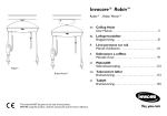
Invacare® RobinTM
User's Manual
Quality Declaration
Congratulations with your new hoist Invacare®RobinTM from Invacare® EC-Høng A/S.
Your new hoist is
medical devices.
-marked in accordance with directive 93/42/EEC concerning
Invacare®RobinTM is developed and constructed with consideration for the user and others
handling or assisting with lifting. Furthermore, the hoist is developed in accordance with
the European Standard EN 10535.
Invacare®RobinTM is supervised and quality controlled throughout the entire production
process, and the finished hoist is inspected by our finished goods control.
Identification label and QA-mark are located on the hoist confirming that the finished
goods control has approved the hoist.
Please read the entire user’s manual before using the hoist.
Invacare®EC-Høng A/S is certified according to ISO 9001 and ISO 13485.
For and on behalf of Invacare®EC-Høng A/S:
René Engskov
Carsten Borup
Managing Director
Technical Manager
DK KVALITETSDEKLARATION
Tillykke med Deres nye personløfter Invacare®Robin fra Invacare® EC-Høng A/S.
Deres nye personløfter er CE - mærket og lever op til alle krav i henhold til direktiv 93/42/EØF om medicinske anordninger.
Personløfteren er udviklet og konstrueret under størst mulig hensyntagen til brugeren samt alle andre, der enten håndterer personløfteren eller hjælper til ved løfteren.
Invacare®RobinTM er udviklet under hensyntagen til de sikkerhedsmæssige krav i den Europæiske Standard EN 10535. Hver personløfter har gennem hele produktionsforløbet været overvåget
og kontrolleret, og den færdige personløfter er blevet inspiceret af vores færdigvarekontrol.
Typeskilt og QA-mærke påsættes personløfteren som dokumentation for, at færdigvare kontrollen har godkendt personløfter. Før ibrugtagning af Deres personløfter skal De gennemlæse
brugermanualen grundigt.
Invacare® EC-Høng A/S er certificeret i henhold til ISO 9001 og ISO 13485.
TM
DE
KONFORMITÄTSERKLÄRUNG
Herzlichen Glückwunsch zu Ihrem neuen Deckenlifter Invacare®RobinTM von Invacare®EC-Høng A/S.
Ihr neuer Deckenlifter ist gemäß der Richtlinie 93/42/EWG für Medizinprodukte CE-gekennzeichnet.
Der Invacare®RobinTM wurde unter Berücksichtigung der Bedürfnisse von Benutzer und Pflegepersonal entwickelt und in Übereinstimmung mit der Europäischen Norm EN 10535
konzipiert und hergestellt.
Während des gesamten Herstellungsprozesses unterliegt der Invacare®RobinTM einer ständigen Qualitätskontrolle und wird im Anschluss nochmals durch unsere Endkontrolle geprüft.
Das Typenschild und QA-Kennzeichen sind am Deckenlifter angebracht, um die Abnahme durch unsere Qualitätskontrolle zu bestätigen.
Bitte lesen die gesamte Bedienungsanleitung, bevor Sie den Deckenlifter in Gebrauch nehmen.
Invacare® EC-Høng A/S ist zertifiziert nach ISO 9001 und ISO 13485.
NL
KWALITEITSGARANTIE
Gefeliciteerd met de aanschaf van uw nieuwe plafondlift RobinTM van Invacare® EC- Høng A/S.
Invacare®RobinTM is CE - gecertificeerd en goedgekeurd conform richtlijn 93/42/EEC betreffende medische hulpmiddelen.
Invacare®RobinTM is ontwikkeld en geconstrueerd met inachtneming van de behoeften van de gebruiker en verzorgers.
Invacare®RobinTM is ontwikkeld in overeenstemming met de Europese Standaard EN 10535.
Gedurende het gehele productieproces is het RobinTM bed gecontroleerd op kwaliteitsaspecten en het complete plafondlift is na productie zorgvuldig gecontroleerd. Het productlabel en de
QA-markering zijn op het plafondlift bevestigd om aan te tonen dat de plafondlift zijn gecontroleerd en goed zijn bevonden door de afdeling productcontrole. Wij verzoeken u vriendelijk de
gehele gebruikershandleiding te lezen voordat u het plafondlift in gebruik neemt.
Invacare® EC-Høng A/S is ISO 9001 en ISO 13485 gecertificeerd.
IT
DICHIARAZIONE DI QUALITÀ
Complimenti per aver scelto il sollevatore da soffito Invacare®RobinTM prodotto da Invacare® EC-Høng A/S.
Il vostro nuovo il sollevatore da soffito è marcato CE - ai sensi della Direttiva 93/42/EEC relativa ai dispositivi medici.
Il il sollevatore da soffito è stato progettato e costruito con un occhio di riguardo per gli utilizzatori e per i loro assistenti. Invacare®RobinTM è stato realizzato nel rispetto della Normativa
Europea EN 10535.
Il sollevatore da soffito è stato oggetto di accurate verifiche qualitative durante l’intero processo produttivo; una volta completato è stato controllato dal nostro servizio prodotti finiti.
Un’apposita targhetta e la marcatura QA sono state apposte sul il sollevatore da soffito a conferma dell’avvenuta verifica e accettazione del prodotto da parte del servizio qualità. Prima di
utilizzare il il sollevatore da soffito vi invitiamo a leggere integralmente il manuale d’uso.
Invacare® EC-Høng A/S è un’azienda certificata ai sensi della Normativa ISO 9001 e ISO 13485.
ES
DECLARACIÓN DE CALIDAD
Enhorabuena por su nueva elevador de techo Invacare®Robin de Invacare® EC-Høng A/S.
Su nueva elevador de techo cuenta con el marcaje CE - de acuerdo a la directiva 93/42/EOF que hace referencia a los aparatos médicos.
Invacare®RobinTM ha sido diseñada y fabricada teniendo en cuenta a los usuarios y las personas que los asisten.
La elevador de techo Invacare®RobinTM ha sido diseñada de acuerdo a la normativa Europea EN 10535.
El proceso de producción del modelo Invacare®RobinTM ha sido supervisado en su totalidad y su calidad inspeccionada, por nuestro control de producto acabado.
La elevador de techo cuenta con una placa y marca CE que confirma que la misma ha sido inspeccionada por el control de producto acabado.
Por favor lea el manual antes de utilizar la elevador de techo.
Invacare EC-Hong A/S es una empresa certificada ISO 9001 e ISO 13485
TM
FR
DÉCLARATION DE QUALITÉ
Félicitations! Vous avez choisi votre nouveau lève-personnes Invacare®RobinTM de Invacare® EC-Høng A/S.
Votre nouveau lève-personnes est marqué CE conformément à la directive 93/42/EEC concernant les dispositifs médicaux.
Invacare®RobinTM a été développé et construit en considérant systématiquement les besoins de l’utilisateur et des tierces personnes lors de la manipulation du lève-personnes ou de son
utilisation. Invacare®RobinTM a été développé conformément au Standard Européen NF EN 10535 et NF EN 60601-2-38.
Invacare®RobinTM a été supervisé et contrôlé tout au long du process de fabrication et le lève-personnes achevé a été inspecté par le contrôle des produits finis. La plaque d’identification et la
marque QA sont placées sur le lève-personnes attestant que le contrôle des produits finis a approuvé le lève-personnes. Le lève-personnes répond aux exigences de l’analyse de risques de la
norme NF EN 14971. Nous vous remercions de lire le Manuel de l’Utilisateur dans son intégralité avant d’utiliser le lève-personnes.
Invacare® EC-Høng A/S est certifiée ISO 9001 et ISO 13485.
PT
DECLARAÇÃO DE QUALIDADE
Parabéns pela sua nova elevador de transferência Invacare®RobinTM da Invacare® EC-Høng A/S.
A elevador de transferência tem a marca CE - em conformidade com a directiva 93/42/EEC referente a aparelhos médicos.
A elevador de transferência foi concebida e desenhada, tendo em consideração o seu utilizador e o seu(s) assistente(s), que o ajudarão a manipular a elevador de transferência. A elevador de
transferência foi concebida em conformidade com o Standard Europeu EN 10535.
Durante todo o processo de fabrico e produção, a elevador de transferência Invacare® RobinTM foi supervisionada e a sua qualidade controlada, sendo o produto final inspeccionado e testado
pelo nosso controlo de qualidade. As etiquetas e a marca QA, são colocadas na elevador de transferência, após a aprovação final da elevador de transferência, confirmando e garantindo a
conformidade com o nosso controlo de qualidade. Por Favor, leia atentamente este manual de utilizador antes de utilizar a sua elevador de transferência.
A Invacare® EC-Høng A/S está certificada em conformidade com ISO 9001 e ISO 13485.
Table of contents
1. Purpose and application . . . . . . . . . . . . . . . . . . . . . . . . . . . . . . . . . . . 7
1.1 Manufacturer:. . . . . . . . . . . . . . . . . . . . . . . . . . . . . . . . . . . . . . . . . . . . . . . . . . . . . . . . . . 7
1.2 Purpose and application. . . . . . . . . . . . . . . . . . . . . . . . . . . . . . . . . . . . . . . . . . . . . . . . . . 7
1.3 Important/warnings. . . . . . . . . . . . . . . . . . . . . . . . . . . . . . . . . . . . . . . . . . . . . . . . . . . . . 8
1.4 Sling’s . . . . . . . . . . . . . . . . . . . . . . . . . . . . . . . . . . . . . . . . . . . . . . . . . . . . . . . . . . . . . . . . 9
1.5 Unpacking and preparation. . . . . . . . . . . . . . . . . . . . . . . . . . . . . . . . . . . . . . . . . . . . . . . 9
1.6 Installing the charging station. . . . . . . . . . . . . . . . . . . . . . . . . . . . . . . . . . . . . . . . . . . . . . 9
1.7 Hoist system installation . . . . . . . . . . . . . . . . . . . . . . . . . . . . . . . . . . . . . . . . . . . . . . . . 10
2. Inspection. . . . . . . . . . . . . . . . . . . . . . . . . . . . . . . . . . . . . . . . . . . . . . 11
2.1 Approvals. . . . . . . . . . . . . . . . . . . . . . . . . . . . . . . . . . . . . . . . . . . . . . . . . . . . . . . . . . . . 11
2.2 Before first-time use . . . . . . . . . . . . . . . . . . . . . . . . . . . . . . . . . . . . . . . . . . . . . . . . . . . 11
3. Description of functions. . . . . . . . . . . . . . . . . . . . . . . . . . . . . . . . . . . 11
3.1 Description of the hoist´s main parts. . . . . . . . . . . . . . . . . . . . . . . . . . . . . . . . . . . . . .
3.2 Operation. . . . . . . . . . . . . . . . . . . . . . . . . . . . . . . . . . . . . . . . . . . . . . . . . . . . . . . . . . . .
3.3 Safety guidelines. . . . . . . . . . . . . . . . . . . . . . . . . . . . . . . . . . . . . . . . . . . . . . . . . . . . . . .
3.4 Charging. . . . . . . . . . . . . . . . . . . . . . . . . . . . . . . . . . . . . . . . . . . . . . . . . . . . . . . . . . . . .
3.5 Charging an emergency battery. . . . . . . . . . . . . . . . . . . . . . . . . . . . . . . . . . . . . . . . . . .
3.6 Battery Maintanance. . . . . . . . . . . . . . . . . . . . . . . . . . . . . . . . . . . . . . . . . . . . . . . . . . . .
11
12
13
13
14
14
4. Accessories. . . . . . . . . . . . . . . . . . . . . . . . . . . . . . . . . . . . . . . . . . . . . 15
4.1 Accessories . . . . . . . . . . . . . . . . . . . . . . . . . . . . . . . . . . . . . . . . . . . . . . . . . . . . . . . . . .
4.2 Transit coupling. . . . . . . . . . . . . . . . . . . . . . . . . . . . . . . . . . . . . . . . . . . . . . . . . . . . . . .
4.3 EC-GantryTM. . . . . . . . . . . . . . . . . . . . . . . . . . . . . . . . . . . . . . . . . . . . . . . . . . . . . . . . . .
4.3.1 EC-Gantry TraverseTM. . . . . . . . . . . . . . . . . . . . . . . . . . . . . . . . . . . . . . . . . . . . . . . . .
4.4 Flexiscope. . . . . . . . . . . . . . . . . . . . . . . . . . . . . . . . . . . . . . . . . . . . . . . . . . . . . . . . . . . .
4.5 Mounting of 4-Point spreader bar. . . . . . . . . . . . . . . . . . . . . . . . . . . . . . . . . . . . . . . . .
4.6 Track switch, manual. . . . . . . . . . . . . . . . . . . . . . . . . . . . . . . . . . . . . . . . . . . . . . . . . . .
4.7 Room to room transfer. . . . . . . . . . . . . . . . . . . . . . . . . . . . . . . . . . . . . . . . . . . . . . . . .
15
16
17
18
19
20
21
22
5. Dismounting & transport . . . . . . . . . . . . . . . . . . . . . . . . . . . . . . . . . 23
5.1 Dismounting. . . . . . . . . . . . . . . . . . . . . . . . . . . . . . . . . . . . . . . . . . . . . . . . . . . . . . . . . . 23
5.2 Transport. . . . . . . . . . . . . . . . . . . . . . . . . . . . . . . . . . . . . . . . . . . . . . . . . . . . . . . . . . . . 23
6. Maintenance & Storage. . . . . . . . . . . . . . . . . . . . . . . . . . . . . . . . . . . 23
6.1 Cleaning. . . . . . . . . . . . . . . . . . . . . . . . . . . . . . . . . . . . . . . . . . . . . . . . . . . . . . . . . . . . . 23
6.2 Storage. . . . . . . . . . . . . . . . . . . . . . . . . . . . . . . . . . . . . . . . . . . . . . . . . . . . . . . . . . . . . . 23
6.3 Maintenance performed by owner . . . . . . . . . . . . . . . . . . . . . . . . . . . . . . . . . . . . . . . . 23
7. Service & lifetime. . . . . . . . . . . . . . . . . . . . . . . . . . . . . . . . . . . . . . . . 24
7.1 Service & lifetime. . . . . . . . . . . . . . . . . . . . . . . . . . . . . . . . . . . . . . . . . . . . . . . . . . . . . .
7.2 Battery. . . . . . . . . . . . . . . . . . . . . . . . . . . . . . . . . . . . . . . . . . . . . . . . . . . . . . . . . . . . . .
7.3 Maintenance. . . . . . . . . . . . . . . . . . . . . . . . . . . . . . . . . . . . . . . . . . . . . . . . . . . . . . . . . .
7.4 Troubleshooting. . . . . . . . . . . . . . . . . . . . . . . . . . . . . . . . . . . . . . . . . . . . . . . . . . . . . . .
24
24
25
26
8. Technical specifications. . . . . . . . . . . . . . . . . . . . . . . . . . . . . . . . . . . 27
8.1 Symbols. . . . . . . . . . . . . . . . . . . . . . . . . . . . . . . . . . . . . . . . . . . . . . . . . . . . . . . . . . . . .
8.2 Installation options of the charger IP41/IP67 . . . . . . . . . . . . . . . . . . . . . . . . . . . . . . . .
8.2.1 IP41. . . . . . . . . . . . . . . . . . . . . . . . . . . . . . . . . . . . . . . . . . . . . . . . . . . . . . . . . . . . . . .
8.2.2 IP67. . . . . . . . . . . . . . . . . . . . . . . . . . . . . . . . . . . . . . . . . . . . . . . . . . . . . . . . . . . . . . .
27
28
28
28
9. Disposal. . . . . . . . . . . . . . . . . . . . . . . . . . . . . . . . . . . . . . . . . . . . . . . . 29
10. Service schedule. . . . . . . . . . . . . . . . . . . . . . . . . . . . . . . . . . . . . . . . . 30
1. Purpose and application
1.1 Manufacturer:
Invacare® EC-Høng A/S
Østergade 3
DK - 4270 Høng
Tel. + 45 58 85 27 22
Fax. + 45 58 85 43 86
1.2 Purpose and application
Purpose
RobinTM is a ceiling mounted hoist, meeting the requirements for hospitals, housing for the elderly, institutions and
private homes. RobinTM is intended for moving clients weighing a maximum of 200 kg including clothing, hoist sling
and other accessories. The hoist is designed for indoor use in normal temperatures and humidity. If you wish to
use the hoist in any other environment, contact Invacare® for advice and instructions.
Use of the hoist for purposes other than transfer of people is not advised and is undertaken at ones own risk.
Conditions
It is a condition of sale that the purchaser of the ceiling hoist must receive training from Invacare® personnel or an
authorised dealer.
When the RobinTM ceiling hoist is used in an institution or in a nursing home, it should always be operated by
specially trained staff, and used in recommended track. systems. The track system must be installed by Invacare®
personnel or an authorised dealer.
Seated to seated transfer
During a seated transfer e.g. from a wheel chair, the RobinTM should be
positioned close to the person to be lifted. The suspension hooks
should ideally be positioned level with the chest and ideally no further
than over the middle of the thigh.
Place the suspension hooks parallel with the user’s shoulders.
See picture.
The sling may now be attached to the suspension hooks.
For placement of the sling, see section »Placement of the sling«.
Lying to lying transfer
Position the suspension hooks above the person to be lifted, aligned to
the users shoulders (see picture). If possible, raise the back portion of
the bed so that the user may be lifted in a seated position.
The sling may now be attached to the suspension hooks.
For placement of the sling, see section »Placement of the sling«.
Placement of sling
The sling straps are to be hooked in pairs (one from the back and one from the leg) on their own suspension
hook.
(Attachment of the sling is described in the respective user manual, the text and picture below is only a principle
explanation).
With the person to be lifted in sitting position, the sling is placed behind the user’s back, e.g. between the back
support of the chair and the user. The client should not sit on the sling. The leg straps are guided forward along
the outside of the thigh and in under the thigh between the knee and the hip joint.
The leg straps are crossed between each other in front of the user. All four sling straps are now ready to be
mounted into the suspension hooks.
When the client is lying down, he/she should be log rolled onto their side. Position the sling in such a way that the
upper edge is in line with the crown of the head. The user is then repositioned onto his/her back and log rolled in
the opposite direction. The sling is then rolled to be flat under the user when he/she is rolled onto his/her back.
The leg straps are then guided in under the thigh bone and crossed in between each other. All four (six) sling
straps are now ready to be attached.
If there is doubt as to the use of the sling, please contact Invacare®.
1.3 Important/warnings
•
•
•
•
•
•
•
Read the entire manual before using RobinTM.
Robin’s max. load of 200 kg must not be exceeded.
If accessories are rated with a lower load than 200 kg, this determines Robin’s maximum load.
RobinTM must only be used to move a patient.
RobinTM must not be used where there is a risk of contact with water.
If the RobinTM is damaged, it must be taken out of use. Call your local Invacare® dealer or Invacare’s
service department.
The cord for emergency stop/emergency lowering is to be adjusted so it is within the user’s range.
Risks when using the hoist:
Risk of entrapment between hook and hook housing.
Risk of entrapment between hooks and sling, when lifting.
Risk of injury to client and carer caused by dangling hooks or hand control.
1.4 Sling’s
Use only -marked sling’s with a rated load equal to or lower than that of the Robin’s max load.
The sling must be suitable for 2 or 4 point spreader bars (please look at Invacare’s brochure concerning slings),
i.e. with sewn lifting loops that can be mounted onto a 2 or 4 point spreader bars.
1.5 Unpacking and preparation
Perform a visual inspection of RobinTM. If the packaging is damaged upon arrival, RobinTM parts must be
thoroughly examined for visible damage or defects. If there is any suspicion of damage, RobinTM must not be used
before qualified service personnel or service technicians have approved the hoist.
It is to be expected, that the hoist´s battery is discharged on account of self-discharge. The hoist must therefore
be charged for up to 2 hours before first time usage, refer to section »Charging«.
The following is to be included in the package:
1. RobinTM.
2. Hand control.
3. User manual. (The charging unit must be ordered separately; part no.: 1446317).
1.6 Installing the charging station
The charging unit should be attached to the wall, or the most practical place, within reach of a socket outlet, to
park the hoist when not in use. It is important to make sure that the hand control can be readily placed into the
charger holder when being charged. Therefore place the charger at a maximum distance of 85 cm under the rail in
which the hoist is mounted.
It is important to make sure that there is access to the mains where the charger is placed.
To mount the charger:, first insert wall fitting with 2 screws, then connect the cable from the charger to the
actual holder, and press the holder onto the mounted wall support.
The wall support for the charger must be mounted with three screws under the holder and at a distance that suits
the length of the charger cable.
Connect the charger to the socket outlet and check that it is operational.
More than one charging unit can be mounted for one hoist, as these can work independently.
Be aware that only an IP67 charger can be mounted in a wetroom, See section 8.2
1.7 Hoist system installation
Prior to fitting the hoist, ensure that the hoist trolley is
mounted.
Remove the end stop that is attached to the rail track. The
trolley can then be inserted into the rail. (It is unimportant
which way the trolley is facing). The end stop must then be
reinstalled. See picture.
When mounting RobinTM, locate the hoist trolley at the
Ø 32 mm round recess in the rail. See picture.
Lift the hoist and push the suspension pin through the hoist trolley. Turn the hoist 90 degrees to the rail’s
longitudinal direction and place it as shown below. (Note: Support the hoist while turning). See picture.
If Robin is correctly mounted into the trolley, it is now possible to pull the trolley back and forth
along the rail.
If there is excessive resistance, or if the trolley unintentionally rolls by itself
due to imbalance in the rail suspensions, adjust the friction brake using a 4 mm
Allen key. See picture.
When the system is installed, the hand control must be connected, and the cord
for the emergency stop/lowering must be adjusted so it is within the user’s reach.
The system must be inspected before use; see section »Before first time use«.
Robin is now ready to be used in the EC-TrackTM system.
When using Robin in other rail systems, an alternative trolley must be used.
Contact Invacare® for information regarding approved systems.
10
2. Inspection
2.1 Approvals
The RobinTM ceiling hoist has been tested and approved in accordance with Lift standard EN/ISO 10535, and is
TÜV approved.
The hoist is -marked in accordance with the medical directive and standard EN/ISO 10535.
2.2 Before first-time use
Before first use, all features of the hoist system must be inspected by a authorised Invacare® installer.
The hoist is not intended to be used together with MEDICAL ELECTRICAL EQUIPMENT.
3. Description of functions
3.1 Description of the hoist´s main parts
Control button UP
Control button DOWN
Connection for
hand control
Connection for
emergency battery
Indicator light
Hand control
Lifting straps
Retainer for
hand control
(accessory)
Emergency stop/
lowering strap
Strap hooks
11
FUNCTIONS ON THE UPPER SIDE
1
2
1. Suspension pin for connecting the hoist to the
hoist trolley.
2. Finger screw for dismounting the top section.
3.2 Operation
Up
Down
Hand control and indicator light
RobinTM is activated when the hand control buttons are pressed. The blue indicator light illuminates when RobinTM
is in use, and turns off automatically after approx. 30 seconds.
The hoist is lifted and lowered by operating the hand control. The control buttons on the underside of the hoist
may also be used for this purpose. The control buttons work independently of the hand control.
Note: The buttons must be depressed in the middle in order to ensure correct function, which is best obtained as
shown in the pictures.
The hoist will automatically run at high speed upwards as well as downwards, when it is not loaded.
The straps must be straight to ensure that they feeds into the apertures correctly. The straps are held taught by
the weight of the hooks, therefore the lifting straps should be freely suspended when the unloaded hoist is running
upwards and downwards.
When the hoist is loaded with a weight of more than 10 kg, the speed will automatically be lowered to a safe level
when moving in both directions.
RobinTM has a built-in soft start, ensuring a more comfortable lifting and lowering movement of the user.
Transport/running in the rail system
The empty hoist can be moved along the rail system by pulling the two lifting straps. The hand control must not be
used to pull the hoist along. During a transfer, the carer should gently push or pull the client sitting in the sling.
12
3.3 Safety guidelines
Emergency stop
If the hoist straps´ moves unintentionally upwards or downwards, pull the »emergency stop« chord.
When the emergency stop is activated, the hoist will not operate. If the emergency stop button is pushed up, the
hoist will be ready for use again.
Emergency lowering
The emergency lowering feature can be used in order to lower a client to the transfer surface if the hoist has
become inoperable. Emergency lowering is operated by continuously pulling the cord.
When the emergency lowering function is activated, all end stops and security functions are
deactivated. It is thereby possible to wind up the lifting straps back up, when activating the
emergency lowering for prolonged periods.
Strap securing/pinch protection
If the lifting straps are guided incorrectly in and out of the hoist, i.e. if the straps has become twisted, the hoist will
automatically turn off.
Note: When attaching the sling to the hooks, and the straps are twisted, the straps will rotate and stretch out,
thus ensuring trouble-free operation.
The pinch protection feature automatically turns off the hoist, if a client unintentionally traps his/her hand in the
lifting strap during a lift. The hoist will stop immediately when the hand makes contact with the strap inlet.
If RobinTM is loaded with a weight of more than 200 kg, the hoist will automatically turn off to safeguard against
overloading.
Electromagnetic interference between the hoist and other electrical products can occur.
To reduce or eliminate such electromagnetic interference, increase the distance between the
hoist and the products or switch off the products!
3.4 Charging
A sound indicator and the flashing indicator light signals when the hoist needs to be charged. The hoist must be
moved along the rail system and parked nearby the wall mounted charger. Attach the hand control to the charger
unit. LED on the charger indicates that charging is taking place. We recommend parking the hoist in the charging
position when not in use.
LED indication
Function
Function duration
Yellow
Battery not connected
-
Yellow
Initializing and analysis of battery
12 - 14 seconds
Red
Fast charge
5 min - 2 hours
Green
Trickle charge
-
Alternating red and green
Fault condition (battery defect)
-
There will still be sufficient power to lower the user from the time when the hoist indicates that charging is
needed.
If the battery should become totally discharged while a transfer is in progress, an external battery may be temporarily connected to the hoist. See the section »Battery«.
NB! It is recommended to interrupt the charging and pull the emergency stop, when the lifter has not been used
for more than 4-6 weeks.
13
Note! It is not possible to use the hoist whilst charging the battery.
If the sound indicator of the Robin beeps, and the blue function lights flash after Robin that has been fully charged
and has been in use for only a short period of time, the battery may be ready to be replaced by a new one. See
section »7.2 Battery«. Another possible option could be that the battery needs to be excercised. See section
»3.6 Battery maintanance«.
3.5 Charging an emergency battery
The emergency battery package is charged by placing the plug in the charger socket. A special adapter is necessary.
The LED light turns green to indicate the unit is fully charged (appox. charging time 2 hours).
3.6 Battery Maintanance
If the sound indicator of the Robin bleeps, and the blue function lights flash are flashing after Robin that has been
fully charged and has been in use for only a short period of time, the battery might need to be exercised.
To enable the battery to be charged fully it is neccessary to exercise the battery from time to time.
This will be dependant on how often the Robin is used. Following a long period of storage, the battery should
be exercised. It is only possible to exercise the battery even if the emergency strap has been pulled down. See
section »5.2 Transport«.
It is suggested that the battery is exercised in situations where a RobinTM is used infrequently, and/or where the
hand control is placed in the charger for long periods of time. In this situation, there will always be capacity enough
for few lifts, but we recommend to exercise the battery as soon as possible afterwards.
Exercise of the battery can be done in two different ways, either by charging and deplete the Robin motor
completely several times, or by placing the battery in an exercising device. See section »4 Accessories«.
Exercise by charging and decharging the Robin motor is done by charging the motor until the light indicator is
green. The motor is then removed from the charger and the straps with load are lowered and raised for one
minute, and then 10 minutes break, continue this procedure until the battery is completely decharged (continue
even when the sound signal for low power bleeps). Charge the battery/Motor and lower and raise the straps until
the battery is decharged again. Repeat this procedure 2-3 times.
The battery can alternatively be exercised in an exercising device, which is available as an accessory for the Robin
hoist. The battery is removed from the Robin motor and placed in the exercising device (see instructions enclosed
with the device).
The exercise method in which charging and deplete the battery several times is carried out is very
time-consumning, we therefore recommend that you use the exercising device.
14
4. Accessories
4���������������
.1 Accessories
Order no.:
Article:
1444013
1444014
1446317
1492102-7035
1451909-7035
1451910-7035
1451911-7035
1451912-7035
1451913-7035
1451914-7035
1450290-7035
1449668-9005
1446269-7012
1488974-7012
1449228-7035
1450289
1449483-9010
1485183-9010
1485183-9006
1451620-7012
1493121
Battery 2 Ah.
Battery 4.5 Ah.
Charger kit IP41 for hand control, black (with 1,8/1,8 m cable, bracket and retainers).
Charger kit IP41 for hand control, grey (with 1,2/2 m cable, bracket and retainers).
Charger kit IP67 for hand control, grey (with 0,1/1 m cable, bracket and retainers).
Charger kit IP67 for hand control, grey (with 0,1/2 m cable, bracket and retainers).
Charger kit IP67 for hand control, grey (with 0,1/3 m cable, bracket and retainers).
Charger kit IP67 for hand control, grey (with 1,2/1 m cable, bracket and retainers).
Charger kit IP67 for hand control, grey (with 1,2/2 m cable, bracket and retainers).
Charger kit IP67 for hand control, grey (with 1,2/3 m cable, bracket and retainers).
Clamp for charger for wall mounting (without transformer), bracket and retainers.
Charger for external battery, black.
Distance clamp (Flexiscope).
4-point spreader bar, 450 mm.
Retainer for hand control, strap mounted.
Gearwheel grease (3 g tube).
Hoist trolley Inalto/Invacare.
Room-to room trolley (white) EC-Track.
Room-to room trolley (grey) EC-Track.
Extended lifting straps with hooks and emergency lowering strap (extra length must be
specified when ordering).
Exercising device NiMH 20 cells of 2,1 Ah.
15
4.2 Transit coupling
The room to room coupling can be used in the rail system, where there is a requirement to transfer a patient
between two rooms.
The room to room coupling can be used when there is traverse system in both rooms or travers system in one of
the rooms and mono rail in the other room.
A
B
C
D
A)
To transfer a patient between rooms, place the hoist with load right under the mono system.
See drawing A point 1.
Then move the Robin and tracking so that the two sections of track line up with each other.
See drawing A point 2.
B) Press the button on the wall mounted control box. See drawing b point 3. When the tracking is locked in
place the green light illuminates and the transfer can be carried out. See drawing B point 4 & 5.
C) When the Robin is safely located on the new section of tracking, the button on the control box, can then be
pressed again to unlock the two sections of tracking. See drawing C point 6 & 7.
D) The green light will then go out, to indicate that the two sections of tracking can be safely moved away from
each other. See drawing D point 8 & 9.
It is esssential that during the transfer process you locate the Robin MoverTM as indicated in the above diagrams,
this will ensure the safe coupling of the tracking sections. If in doubt , or you experience difficulty in coupling the
tracking, contact your Invacare dealer.
16
4.3 EC-GantryTM
The EC-GantryTM is used where there is a requirement for a free standing rail system.
Height range for EC-GantryTM without wheels: 216-251 cm
Height range for EC-GantryTM with wheels: 195-230 cm
251 cm
244 cm
237 cm
230 cm
223 cm
216 cm
The EC-Gantry is available with or without wheels.
The wheels of the EC-GantryTM must be locked before performing any lift.
To increase the height of the EC-Gantry, pull the leg section upward.
To decrease the height of the EC-Gantry, pull the handle as indicated above, adjust the EC-GantryTM to the desired
height and then release the handle to allow the leg section to lock back into place.
Wih regards to the safety of the patient, it is recommended that the EC-GantryTM is not moved
with a patient hanging in the sling.
It is important that the EC-GantryTM is placed on a level surface with regards to the risk of tipping.
Please observe that there is a risk of the patient swinging into the EC-Gantry´s legs.
There is a risk of carer stumbling over foot of the EC-GantryTM system.
There is a risk of tipping if the patient is very unsettled or suffers from spasm in the sling.
Never leave a patient in the sling unattended.
17
4.3.1 EC-Gantry TraverseTM
The EC-Gantry TraverseTM is used where there is a requirement for a free room covering standing rail system.
Height range for EC-Gantry TraverseTM: 218-253 cm
253 cm
246 cm
239 cm
232 cm
225 cm
218 cm
It is important that the EC-Gantry TraverseTM is placed on a level surface with regards to the risk
of tipping.
Please observe that there is a risk of the patient swinging into the Gantry´s legs.
There is a risk of tipping if the patient is very unsettled or suffers from spasm in the sling.
Never leave a patient in the sling unattended.
18
4.4 Flexiscope
Scope
FlexiscopeTM is used with the Invacare© RobinTM ceiling hoist in connection with the transfer or moving of disabled
patients who require extended distance between the slings shoulder straps. Max. load: 200 kg.
Installation
Installation of FlexiscopeTM on
the lifting straps is carried out
according to the illustrations.
Adjustment
Alignment of the width is made by pulling the button A while moving the strap bar B to the desired position.
Note! Ensure that the bar is correctly engaged.
Maintenance and cleaning
Cleaning in connection with daily use:
• All painted surfaces can be whiped off with a damp cloth. Only household detergents are allowed.
Never use acids, alkalines or solvents such as acetone or cellulose thinner.
• Desinfection of FlexiscopeTM - it must be whiped over with officially approved detergents only.
• The black cover is removed from FlexiscopeTM and can be mashine washed at 70ºC - do not tumbledry, bleach or
dry clean.
19
4.5 Mounting of 4-Point spreader bar
• Lower the Robin lifting straps down to a suitable height and mount the spreader bar shown on the illustration
below.
• Use only the spreader bars produced for Robin.
• Ensure that the spreader bar suits the client and the type of lift required.
Ensure the spreader bar is correctly mounted before use.
20
4.6 Track switch, manual
The track switch is used in track systems where a change in direction is required during movement of the patient.
The track switch is operated by pulling the cords on either side - this change in direction must be carried out
before the client is guided into the drive switch area. The direction is changed, and the hoist will take the direction
to the side where the cord is pulled.
The track switch is mechanically secured against derailing.
21
4.7 Room to room transfer
1.
The two hoists are moved as close to the doorway as possible.
The sling is attached to hoist A.
The lifting straps on hoist A are lowered as far as possible with
concideration to the patient´s comfort.
2. The two lifting straps on hoist B are lowered as much as necessary to
attach them to the sling.
Note! Ensure that the lifting strap hooks are installed correctly.
3. The lifting straps of hoist B are raised while the straps on hoist A are
lowered. Continue until the patient is completely suspended by hoist B.
4. The lifting straps on hoist A is now uncoupled from the sling and rewound.
Note! Beware of dangeling hooks or hand control.
5. The lifting straps on B are rewound to the desired height. The room to
room transfer is now carried out.
22
5. Dismounting & transport
5.1 Dismounting
When dismounting RobinTM, please see section »Installation of hoist system«.
5.2 Transport
The emergency strap must be pulled, when the RobinTM motor is demounted from the tracks, for transport or
storage, otherwise the RobinTM can be accidentally activated. See section »6.2 Storage«.
During transportation, the hoist must be placed on a soft surface, e.g. a cloth or foam rubber mat. Make sure that
RobinTM remains upright whilst being moved.
We recommend using the original packaging for transportation under the following conditions:
• Temperature between -30° and +50°C.
• Humidity between 10 og 70% RH.
• Pressure between 700 og 1.100 hPa.
-30 → 50°C
-22 → 122°F
10 → 70%
700 → 1.100 hPa
6. Maintenance & Storage
Only Invacare authorised personnel should perform maintenance and service. Daily inspection should be carried
out by the carer after reading the manual. Six monthly inspection according to UK LOLER 1998 regulations should
be done also. Spare parts list and wiring diagram can be obtained from Invacare®or be down loaded from www.
invacarebeds.dk.
6.1 Cleaning
Cleaning in connection with daily use:
·
•
·
·
Lifting slings are to be washed in accordance with manufacturers instructions.
RobinTM and the hand control can be wiped with a moistened cloth. Only common cleansing agents must
be used; never use acids, and solvents.
The strap hooks must be cleaned with water and common cleansers.
If disinfection is required, dry thoroughly with known brands of liquid detergent.
6.2 Storage
RobinTM should be stored in a dry place under conditions mentioned in section 5.2 »Transport«.
Pull the emergency strap before the Robin is stored, to avoid unwanted activation of the Robin and furthermore to
protect the battery from damage, when the hoist is stored for a longer period without being used.
If the emergency strap is not pulled the capacity of the battery will deplete completely, and will be irreparably
damaged.
When the emergency strap is pulled during storage it will be possible to regain the entire capacity of the battery
by exercising the battery, see section »3.6 Battery maintanance«.
6.3 Maintenance performed by owner
Check the lifting straps on a regular basis. If there are signs of damage in any way, do not use the hoist. Contact
your local Invacare® dealer for advice. The straps must only be replaced by persons authorised by Invacare®.
23
7. Service & lifetime
7.1 Service & lifetime
To ensure the optimal function and safety of Robin, it is important to perform service and maintenance in
accordance with the manual.
Maintenance must be carried out following national regulations, and at least yearly.
According to the Factories Inspectorate regulations, Robin has to undergo an annual service by an Invacare®
authorised person.
Durability and lifetime expectancy is based on an annual service programme performed by an Invacare®
authorised dealer or Invacare®.
Robin has an expected lifetime of approx. 10 years. After 10 years use, it must be inspected by qualified personnel
before further use.
If the hoist is used in localities with increased humidity, a reduction in lifetime must be expected.
Spare part list for Robin and EC-Track can be obtained from Invacare®.
7.2 Battery
To change battery.
If battery replacement is necessary, RobinTM must be removed from the track system. Please see section
»dismounting«. Release the upper part of the hoist by removing two screws. See picture.
1
2
3
4
5
6
7
Remove the battery pack inside the hoist by unplugging the wires, and replace it with a new one.
Re attach the upper part of the housing.
Important! Use only Invacare®recommended batteries, see section »Accessories«.
The battery must be located as shown in picture 7.
If the battery housing is damaged, do not use the battery.
It is not necessary for an approved service person to carry out the battery change.
24
Use of emergency batteries
Should the need for immediate use of Robin arise at a time when the hoist has a discharged battery, a Invacare®
emergency battery can be used.
This battery is connected to the underside of the motor, hanging freely during client transportation.
Use the emergency battery only when absolutely necessary. Always recharge this battery after use, please
see section »Charging«.
The emergency battery is an accessory that can be ordered from your Invacare® dealer, see section »Accessories«.
Important! Use only Invacare®recommended emergency batteries.
7���������������
.3 Maintenance
When performing annual or regular maintenance, all parts designed to carry load must be tested at maximum
capacity (both hoist and track system). All safety features must be checked. A function test of the system with
1.5 x maximum load must also be performed.
During the service, all parts that is exchanged and all work carried out, must be documented. The worn and
defective parts must be replaced with new spare parts from Invacare. Inspection of the hoist and track system
must be carried out by a qualified Invacare® authorised dealer.
To record the details, please use the service schedule on page 25.
EC-Track system inspection
•
•
•
•
•
•
All bolts/fixtures in walls and ceiling must be checked and re tightened if necessary.
The end stop on the tracks is checked, adjusted if necessary and re tightened.
Systems with track connections should be checked and realigned if the connection has become mis-aligned
during use.
Test the trolley and the traverse trolley. Check for noise and smooth movement.
For a traverse system, check all functions and connections.
Check the friction brake on both the hoist- and traverse trolley, and adjust accordingly.
Hoist inspection
Mechanical parts:
• Check the suspension pin and the cross axle.
• Check the steel- and plastic gear wheels for wear and damage.
• If the gearwheels are dry, use the gearwheel grease (see »accessories«).
• Check the loose strap sensor and adjust, if necessary.
• Check the guide cylinder and the end stop.
• Check the straps for wear and damage.
• Check the hooks for damage. Check the screws and pins.
25
Electrical parts:
• Check the wiring for damage and secure connections.
• Check the micro switches for clamping and their mechanical function.
• Check the hand control for damage and function. Make sure that the hand control is securely connected.
• Check the emergency stop/lowering.
7.4 Troubleshooting
Service and maintenance of RobinTM must only be performed by personnel who have received the necessary
instruction and training.
Symptom
Possible cause
Action
The hoist is not responding
correctly when pressing the hand
control buttons, and the up/down
buttons on the hoist are not
functioning.
1) The emergency stop is activated.
1) Depress the emergency stop
button.
2) Put the hoist on charge or use
the emergency battery.
3) Replace the fuse.
2) The battery is discharged.
3) The fuse is blown.
The hoist is not responding correctly when pressing the hand
control buttons, but the up/down
buttons on the hoist are
functioning.
1) The hand control is not
connected correctly.
2) The hand control is defect.
1) Secure the plug.
The straps will only move
downwards and not upwards.
1) The battery is nearly discharged.
1) Put the hoist on charge or use
the emergency battery.
2) Reduce the load (the hoist is
equipped with a over-current
safety system). Check the hand
control, it´s connection and the
re-entering endstop.
2) The load is to high.
2) Replace the hand control.
The straps will only move upwards and not downwards.
1) The hand control is defect.
2) The loose strap function is
activated.
1) Replace the hand control.
2) Check the loose strap switch.
The hoist speed is the same with
and without load.
1) The non-load quick movement
function is activated permanently.
1) Check the quick movement
switch.
The lifting straps are twisted, and
do not straighten out.
1) The lifting hooks do not turn
freely enough.
2) The straps are frayed.
1) Clean or replace the hooks.
1) Defect bearings, gearwheels or
motor.
1) Replace the hoist.
The hoist emits excessive noise
when activated.
2) Replace the straps.
If the above mentioned does not solve the problem, please contact Invacare® Service Department.
26
8���������������������������
. Technical specifications
Dimensions (HxBxD)
19x47x25 cm.
Max. lifting capacity
200 kg.
Number of lifts per charge
65 lifts of 0.5 m with 80 kg.
Lifting velocity at 200 kg load
2 cm/s.
Max lifting interval
250 cm.
Height from celling to sling hook
41 cm.
Total weight without sling
7 kg.
Electrical connection of charger
230V AC 50Hz
Voltage/current between charger/hoist
24V DC 900mA / 50mA.
Charging time (with 2 Ah battery)
Max 2 hours
20 pcs. 1.2V / 2.0 Ah AA
20 pcs. 1.2V / 4.5 Ah
Batteries
Intermittence
8%
8.1 Symbols
Warning.
= 200 kg
SWL (Safe Working Load) = Max. load (patient + sling + other accessories).
Class II equipment.
Type B equipment - patient not separated from ground.
CE - marking.
The product should be reused where possible.
27
8.2 Installation options of the charger IP41/IP67
8.2.1 IP41
May not be used in a wetroom environment.
8.2.2 IP67
The charger is designed according to IP67, and can therefore be used in wet locations according to these illustrations:
Bath tub
Shower basin
Shower without basin
Shower with fixed partition
Shower head
Shower head
Installation of the charger is recommended in zone 2 and 3.
28
9. Disposal
This product has been supplied from an environmentally aware manufacturer that complies with the Waste
Electrical and Electronic Equipment (WEEE) Directive 2002/96/CE
This product may contain substances that could be harmful to the environment if disposed of in places (landfills)
that are not appropriate according to legislation.
The »crossed out wheelie bin« symbol is placed on this product to encourage you to recycle wherever possible.
Please be environmentally responsible and recycle this product through your recycling facility at its end of life.
All electrical parts must be removed and disposed of as electrical components.
Plastic parts must be recycled or incinerated.
Steel- and aluminium parts must be disposed of as metal scrap.
Batteries: Local and national regulations for environmental recycling must be followed.
Batteries must always be delivered to an approved collection place.
Disposal must always follow the relevant local laws and regulations for waste and scrap.
29
10. Service
���������������
schedule
Service and maintenance of the hoist must be carried out only by trained/experienced personnel
Personnel hoist serial number: __________________________________
Inspection point: Date:
Inspection of the track system
All bolts/fixtures to wall and ceiling must be checked and
re-tightened if necessary.
End stops on the tracks must be checked, moved if necessary
and re-tightened.
Systems with track connections should be checked and
re-aligned if the connection has become mis-aligned during
use.
Check trolley and traverse trolley.
Check trolley wheels for smooth movement and abnormal
noise.
Check friction break adjustment on trolleys.
Adjust if necessary.
Inspection of hoist
Mechanical parts:
Check suspension- and cross pin.
Check steel- and plastic gear wheels for wear and damage.
If gear wheels are dry, apply gearwheel grease
(see »accessories«)
Check loose strap sensor and adjust if necessary.
Check guide cylinder and end stops.
Check straps for wear and damage.
Check the lifting hooks, screws and pins for wear and damage.
Electrical parts:
Check the wiring for damage and correct connections.
Check micro switches for clamping and mechanical function.
Check hand control for damage and function.
Make sure that the hand control is connected correctly.
Check emergency stop and emergency lowering.
30
Customer Sales and Service
Denmark
INVACARE A/S
Sdr. Ringvej 39
DK-2605 Brøndby
Phone: +45 36 90 00 00
Fax: +45 36 90 00 01
www.invacare.dk
[email protected]
Belgium & Luxemburg
INVACARE N.V.
Autobaan 22
B-8210 Loppem, Brügge
Phone: +32 50 83 10 10
Fax: +32 50 83 10 11
www.invacare.be
[email protected]
France
INVACARE Poirier S.A.S
Route de St. Roch
F-37230 Fondettes
Phone: +33 2 47 62 64 66
Fax: +33 2 47 42 12 24
www.invacare.fr
[email protected]
Sweden & Finland
INVACARE AB
Fagerstagatan 9 / Box 66
S-163 91 Spånga
Phone: +46 8 761 70 90
Fax: +46 8 761 81 08
www.invacare.se
[email protected]
Netherlands
INVACARE B.V.
Celsiusstraat 46
NL-6716 BZ Ede
Phone: +31 318 695 757
Fax: +31 318 695 758
www.invacare.nl
[email protected]
Italy
INVACARE MECC SAN S.R.L.
Via dei Pini 62
I-36016 Thiene (VI)
Phone: +39 0445 38 00 59
Fax: +39 0445 38 00 34
www.invacare.it
[email protected]
Norway & Iceland
INVACARE AS
Grensesvingen 9
Postbox 6230 Etterstad
N-0603 Oslo
Phone: +47 22 57 95 00
Fax: +47 22 57 95 01
www.invacare.no
[email protected]
Germany
AQUATEC GmbH
Alemannenstrasse 10
D-88316 Isny
Phone: +49 75 62 700 0
Fax: +49 75 62 700 66
www.aquatec.de
[email protected]
United Kingdom & Ireland
INVACARE LTD
South Road
Bridgend Industrial Estate
UK-Bridgend, CF31 3PY
Phone: +44 1 656 664 321
Fax: +44 1 656 667 532
www.invacare.co.uk
[email protected]
Spain
Portugal
INVACARE Lda
Rua Senhora de Campanhã 105
P-4369-001 Porto
Phone: +351 225 1059 46/47
Fax: +351 225 1057 39
www.invacare.pt
[email protected]
New Zealand
INVACARE NZ
4 Westfield Place,
Mt. Wellington
Auckland
Phone: +64 9 917 3939
Fax: +64 9 917 3957
www.invacare.co.nz
[email protected]
Australia
INVACARE Australia Pty Ltd
1 Lenton Place, North Rocks
NSW 2151
Phone: +61 2 8839 5333
Fax: +61 2 8839 5353
www.invacare.com.au
[email protected]
Austria
MOBITEC MOBILITÄTSHILFEN GmbH
Herzog Odilostrasse 101
A-5310 Mondsee
Phone: +43 6232 5535 0
Fax: +43 6232 5535 4
www.mobitec-austria.com
[email protected]
INVACARE S.A.
C/Areny S/N
Poligon Industrial de Celrà
E-17460 Celrà (Girona)
Phone: +34 972 49 32 00
Fax: +34 972 49 32 20
www.invacare.es
[email protected]
Switzerland
MOBITEC REHAB AG
Benkenstrasse 260
CH-4108 Witterswil
Phone: +41 61 487 70 80
Fax: +41 61 487 70 81
[email protected]
Invacare® EC-Høng A/S
Ident. no.: 1485245
Version: 05
Date:
11.2006
Manufacturer:
INVACARE EC-Høng A/S
Østergade 3
DK-4270 Høng
www.invacarebeds.dk


