1
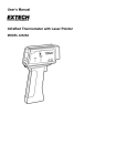
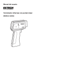
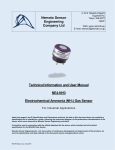
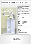
USER MANUAL &
CHARACTERISATION DATA
NAP-505 Electrochemical Carbon Monoxide Gas Sensor
Head Office: N.E.T. Srl Via A. Manzoni, 19 – 20010 Pogliano Milanese, Milan, ITALY
Tel: (+39) 02 935 44190
Fax: (+39) 02 935 40347
WEB: www.nemototech.com E-MAIL: [email protected]
NAP505-CD.doc, issue 3, April 2004
INTRODUCTION
Nemoto & Co. Ltd was established in 1941 and continues to develop unique technologies for the Safety,
Security and Health markets. Using our unique experience of fine chemical preparation and printing, we
were able to enter the gas sensor market in 1979 with a range of high-quality hot-wire type sensors
(pellistors). Nemoto is now one of the World’s leading manufacturers of chemical sensors and has so far
delivered over 30-million devices to the market.
As a result of three-years’ development at our Tokyo R&D centre, we released our first electrochemical
gas sensors in 2000.
The NAP-505 Gas Sensor is a new, low–cost 3 Electrode Electrochemical cell designed for the detection
and measurement of carbon monoxide in the range 0-1000ppm, in domestic carbon monoxide detectors,
fire detectors and air quality monitors. The NAP-505 easily meets the requirements of all international
performance standards (UL2034, EN50291 and CSA22.2) without the use of electronic compensation.
To date, high performance 3-electrode gas sensors have been mainly used in industrial applications due
to their high cost of manufacture. By using our experience of design for manufacture and our high volume
production facilities in Japan and China, we have successfully reduced the cost of the NAP-505
significantly whilst being able to maintain the highest levels of performance.
This characterisation document does not constitute a specification but is intended as a guide,
informing the instrument designer of the performance characteristics of the sensor which were
observed by Nemoto Environmental Technology's Engineers.
It should be read in conjunction with Technical Information Sheet DS-N-NAP505, which includes the
full technical specification for the NAP-505 Gas Sensor.
NAP505-CD.doc, issue 3, April 2004
- page 2 of 16 -
PRINCIPLES OF OPERATION
The NAP505 consists of 3 porous noble metal electrodes separated by an acidic aqueous electrolyte,
housed within a plastic (PPO) enclosure. Gas enters the cell via a gas phase diffusion barrier (capillary)
and a charcoal based filter that removes unwanted gases which might interfere with the sensors
performance or give a false signal. An electrolyte reservoir ensures an excess of electrolyte is available at
all times, and the sensor is vented to ensure that the internal and external pressure of the sensor is in
equilibrium.
In operation, gas enters the cell via the capillary and filter, and comes into contact with the ‘working’
electrode. Any carbon monoxide present undergoes the following (oxidation) reaction:
CO + 2H2O → CO2 + 4H+ +4eThe CO2 generated vents away from the cell via the capillary, whilst the hydrogen ions (H+) migrate into
the electrolyte within the cell. The electrons (e-) generated at the working electrode are collected by the
external circuit via a metal strip in contact with it, in the form of a small (nA) electric current.
The reaction at the working electrode is balanced by a reciprocal (reduction) reaction at the ‘counter’
electrode, using Oxygen from the surrounding atmosphere.
O2 + 4H+ + 4e- → 2H2O
The electrons consumed in this reaction are supplied by the external circuit via a metal strip in contact
with the counter electrode.
NAP505-CD.doc, issue 3, April 2004
- page 3 of 16 -
Thus water is consumed whilst Hydrogen ions are generated at the working electrode, whilst the water is
re-created and hydrogen ions are consumed at the counter electrode. At the same time, the reaction at
the working electrode generates electrons, whilst the reaction at the counter electrode consumes
electrons. By connecting the working and counter electrodes together via a special circuit, flow of
electrons between the two electrodes is measured as a nA level current signal proportional to the carbon
monoxide concentration.
The ‘reference’ electrode maintains the healthy operation of the cell. It is surrounded by electrolyte, sees
no gas and no current is allowed to be drawn from it. Its electrochemical potential hence always remains
constant at a level known as the “rest air potential” and this is used to regulate the potential of the working
electrode, regardless of the current it is generating during operation. The use of a reference electrode in
this way (i.e. three-electrode operation) helps to extend the working range of the sensor, improves
linearity and results in a number of performance benefits compared with similar sensors working with 2electrodes only.
NAP505-CD.doc, issue 3, April 2004
- page 4 of 16 -
FEATURES
Electrochemical gas sensors have the following superiority to conventional semiconductor type and hotwire type gas sensors.
•
•
•
•
•
•
•
•
Linear output in proportion to gas concentration
High reproducibility
Highly gas specific
Unaffected by humidity
Stable output for long periods
Low power consumption because no heater is used (can be battery operated)
Small and lightweight (can be used in portable devices)
No mechanical structure so highly resistant to shocks and vibrations.
NAP-505 has been developed from our accumulation of technologies in production of hot-wire type gas
sensors, long research experience into catalysts, fine printing, and assembling of sensors. The NAP-505
is small and less-expensive, but has high sensitivity, long life, and leak-free performance even under
severe operating conditions.
Small-size
NAP 505 is one of the smallest electrochemical sensors in the world to accommodate the design and
manufacture of smaller gas detection products and allowing space for additional features.
Air vent
The electrolyte used for chemical sensors is very hygroscopic, i.e. it has affinity for water, and its volume
varies depending on ambient temperature and humidity. This variation causes pressure inside the sensor
to rise and fall. In the worst case the electrolyte may leak out of the sensor and damage the circuitry
around it.
To prevent this, the NAP-505 combines small size with an air vent capability. This maintains equilibrium
between internal and external pressures and allows the sensor to be used in any orientation and under
high temperature and humidity conditions.
Solderable
Conventional electrochemical sensors can not be soldered directly to pins because the rapid temperature
increase causes thermal deformation of the plastic housing and subsequent leakage of electrolyte. The
NAP-505 uses a unique electrode pin and socket design to dissipate heat and minimize the affect of high
temperature. This simplifies the assembling process as the NAP-505 can be soldered directly to the
PCB.
NAP505-CD.doc, issue 3, April 2004
- page 5 of 16 -
PERFORMANCE DATA
1) Linearity
Linearity of NAP-505
(using basic operating circuit)
1
0.9
0.8
Output voltage (V)
0.7
0.6
0.5
0.4
0.3
0.2
0.1
0
0
500
1000
1500
2000
2500
CO gas concentration (ppm)
NAP505-CD.doc, issue 3, April 2004
- page 6 of 16 -
2) Uncompensated Temperature Dependence:
The following graph illustrates the typical effect of temperature on the output signal of the NAP-505, for a
sensor calibrated at 20oC
NAP-505 Temperature Dependence
140
120
% Original Output
100
80
60
40
20
0
-30
-20
-10
0
10
20
30
40
50
60
o
Temperature ( C)
NAP505-CD.doc, issue 3, April 2004
- page 7 of 16 -
3) Cross Sensitivities:
The following table gives cross sensitivity information for a variety of commonly encountered gases. The
selectivity of the NAP-505 is has been designed to comply with relevant standards such as EN50291,
TUV standards and UL2034.
Test gas
Carbon monoxide
Hydrogen
Methane
Iso-butane
Carbon dioxide
Sulfur dioxide
Hydrogen sulfide
Nitrogen monoxide
Nitrogen dioxide
Ammonia
Ethyl acetate
Heptane
Ethanol
HMDS (Silicone)
Gas Concentration
Tested (ppm)
100
500
5000
2500
5000
25
10
30
30
100
200
500
2000
10
Typical carbon-monoxide
reading (ppm) Equivalent
100
200
0
0
0
0
0
0
< 10
0
0
0
< 30 (30 min Exposure)
0 (40 min exposure)
NAP505-CD.doc, issue 3, April 2004
- page 8 of 16 -
4) Response Characteristics
The following are plots of responses and recovery times for exposures to carbon monoxide at various
concentrations:
NAP-505 EN50291 5000ppm CO test
(using basic operating circuit)
2.5
CO:5000ppm(15min.) test
Output Voltage (V)
2
1.5
1
0.5
After 60 min.
CO:50ppm test
No.1
No.2
No.3
No.4
No.5
No.6
No.7
No.8
No.9
No.10
No.11
No.12
No.13
No.14
No.15
No.16
No.17
No.18
No.19
No.20
0
Sampling Time
NAP505-CD.doc, issue 3, April 2004
- page 9 of 16 -
5) Stability, Environmental and Ruggedness
The NAP-505 has been tested extensively to ensure that it can survive harsh environments and rough
treatment, both in storage and during operation without failure or undue performance effects. A selection
of the tests, with results, are outlined below:
TEST
Storage at High Temperature:
Sensor stored at 50oC, 40%RH for 1000 hours. Output
signal tested against original at STP following storage
Storage at High Temperature/Humidity:
Sensor stored at 50oC, 90%RH for 1000 hours. Output
signal tested against original at STP following storage.
Storage at Low Temperature:
Sensor stored at -20oC, for 1000 hours. Output signal
tested against original at STP following storage
Storage at Low Humidity:
Sensor stored at 25oC, <20%RH for 1000 hours. Output
signal tested against original at STP following storage.
Cool/Heat Cycle:
-20oC, for 30 minutes, +50oC for 30 minutes
10 cycles
Shock Test:
Sensor dropped onto concrete floor from 1m height
5 drops
RESULTING OUTPUT DRIFT
< +/- 15%
< +/- 10%
< +/- 5%
< +/- 10%
< +/- 10%
< +/- 5%
NAP505-CD.doc, issue 3, April 2004
- page 10 of 16 -
6) Long-Term Drift Characteristics
Zero Stability of NAP-505 (20oC)
500
Output Current (nA)
250
0
-250
-500
0
50
100
150
200
250
300
350
400
450
Time (days)
Span Stability of NAP-505 (20oC)
50
Output per ppm CO (nA)
40
30
20
10
0
0
50
100
150
200
250
300
350
400
450
Time (days)
NAP505-CD.doc, issue 3, April 2004
- page 11 of 16 -
DEFINITIONS
Base-line / Base-line shift
Base line means the output level in clean air. The output current value at 20oC would be less than
250nA, but this tends to increase as the ambient temperature rises more than 30oC. The base-line shift
means this variation of the output level, i.e. a maximum of 500nA would be put out at 50oC. This baseline shift should be taken into account to optimise overall accuracy. In this manual, the output values
are calculated to be equivalent to CO gas concentrations.
Gas sensitivity / Output signals
Using the NAP-505, 40 ± 10nA is generated at 1ppm of CO gas. For instance, the generated current
value will be about 8µA at 200ppm of CO gas (200ppm x 40nA). This generated current is generally
recorded as a voltage produced by a Current – Voltage converting circuit. In our recommended circuit,
as the conversion is done through a resistor of 10 KΩ.
Response time (t90)
This is the time taken to reach to 90% of the maximum output value in clean air.
Repeatability
This is the maximum variation of output signals when tests are repeated under the same measuring
conditions (temperature, humidity, gas concentration etc.). The repeatability of NAP-505 is ± 2%, and
this means that all of the test results would fall in the range of 98% ∼ 102%.
Temperature dependence
All electrochemical sensors are affected by changes in the ambient temperature and the output
increases as the ambient temperature rises. This is caused by the rate of oxidation reaction on the
surface of the catalyst, the dispersibility of the gas in the capillary, and the thermal affects on the
mobility of ions in the electrolyte. This temperature dependency can be compensated relatively easily
by using a NTC thermistor.
NAP505-CD.doc, issue 3, April 2004
- page 12 of 16 -
NOTES FOR CIRCUIT DESIGN
1) Basic operational circuit
0.1μF
-V
0.1μF
4
8
counter
10kΩ
2
3
TH1
TH
16kΩ
0.1μF
1μF
+V
-V
4
8
0.1μF
3
Output Voltare
6
OP97
+
7
1
2
-
10Ω
6
OP97
7
1
Reference
15kΩ
Working
+
NAP-505
-
This circuit uses OP97
operational amplifier, that is
easily obtainable and relatively
low power. The temperature
dependency of NAP-505 is
compensated by NTC thermistor
that has 3435K of B constant
made by Ishizuka Denshi. Thus
the output accuracy can be
within ± 10% in the range of 10oC ∼ 50oC. Any thermistor
with a B-constant around 3500K
and resistance value (R25) of 10
KΩ can be used.
10Ω
0.1μF
+V
TH:NTC Thermistor
R 25 =10kΩ B=3435k
103AT(Ishizuka Electronic Corp.)
2) Low power consumption circuit
For general operational circuits, operational amplifiers such as OP97 used in our recommended circuit or
classical OP07 can be used without problems. However for battery-operated circuits for portable devices,
lower power consuming operational amplifiers are required. For example, the NJM4250 works at as low
as 0.1 mA (max) with a supply voltage of ± 1 V ∼ ± 18 V. For simpler circuits with single power supply,
battery-operation with 2 ∼ 3 V is possible and OP90 (20µAmax) or the like can be used.
For a longer battery life, a pulsed operation may be utilised, e.g. 2 minute-off after 30-second operation, in
order to save battery power consumption.
4
8
counter
2
Reference
6
7
1
3
+
Working
FET
4
8
V
Output Voltare
6
7
1
+
2
3
-
NAP-505
-
When using an electrochemical sensor in cycled
operation, transient signals may be seen just
after power on and power off. Under normal
operation 1 ∼ 2 minutes would be required for
output stabilization. To eliminate this effect it is
necessary to maintain a short-circuit between
the working electrode (W) and the reference
electrode (R) when the power supply is off. In
this example the short-circuit is maintained using
a FET so that the short is automatically broken
during the power supply is on. Using this
approach, the output is stabilized within 10
seconds after the power on. Sampling the
output signal just before the power off enables
accurate measurement data whilst saving
battery power consumption.
NAP505-CD.doc, issue 3, April 2004
- page 13 of 16 -
3) Battery operation
0.1μF
4
8
counter
10kΩ
2
3
TH1
TH
16kΩ
10kΩ
4
8
6
+
2
OP90
Output
Voltage
7
1
3
-
10Ω
0.1μF
91kΩ
+V
1μF
This ensures a linear signal
across the full measurement
range. However if strict
measurement results are not
required in the range less than
50ppm, this virtual zero may
not be needed.
6
OP90
7
1
Reference
15kΩ
Working
+
NAP-505
-
When exposed to CO gas, the
potential of the counter
electrode will need to move
negative in respect to the
working electrode. When a
single power source (i.e.
battery or D.C.) is used, it is
necessary to maintain a virtual
zero above 0V to allow optimal
electrochemical performance.
In this case, we recommend
that this is between 0.2~0.5V.
0.1μF
TH:NTC Thermistor
R 25 =10kΩ B=3435k
103AT(Ishizuka Electronic Corp.)
+V
Characteristics of Single Power Circuits
(using single power operational amplifiers)
250
Output Voltage (mV)
200
150
100
50
0
0
100
200
300
400
500
600
CO Concentration (ppm)
Zero = 0V
Zero = 0.5V
4) Self-diagnostic system
For many applications, it is necessary to automatically identify critical sensor failure and in particular open
and short circuit conditions. Nemoto has developed a patented electrical method suitable for battery and
mains voltage operation. If this is required, please contact Nemoto and we will be happy to provide further
details subject to a non-disclosure agreement.
NAP505-CD.doc, issue 3, April 2004
- page 14 of 16 -
NOTES
1) Long-term drift of gas sensitivity
All electrochemical gas sensors lose sensitivity over time due to small changes on the surface of the
working electrode, reducing its oxidation capability. To reduce this, the NAP-505 uses a newly developed
electrode catalyst that will not deteriorate by more than 5% / year. Typically, these changes are limited to
less than 5% but we recommend that this deterioration should be taken into account when designing
application circuits.
2) Environmental affects on gas sensitivity
Due to the hygroscopic nature of the electrolyte used in electrochemical sensors, moisture is absorbed
from or released to the surrounding atmosphere. In high humidity moisture is absorbed, causing an
increased sensitivity. In low humidity moisture is released back to the atmosphere and the sensitivity
decreases. Conventional electrochemical gas sensors show annual variation of gas sensitivity as much
as 10 ∼ 20%.
The NAP-505 utilises an advanced electrolyte management design and, combined with the unique
electrode catalyst structure, these changes can be greatly reduced. Under normal operating conditions,
gas sensitivity should change by no more than ± 5% of the output value. The NAP-505 is designed so that
all changes due to moisture uptake/release are completely reversible.
If the gas intake area of the sensor is blocked with water drops or other liquid, gas cannot enter the
sensor. The NAP-505 is fitted with an integral hydrophobic barrier to prevent this, but we recommend the
use of additional membrane barriers if the sensor in highly condensing RH conditions.
CO gas is almost the same weight as air, but as it is a combustion by-product it will usually be heated and
therefore rise. CO detecting devices should be installed at least 5ft from the floor and preferable on the
upper part of walls or ceilings.
Under normal environmental conditions (room temperature and humidity), the warranty period for the
NAP-505 is 5 years from the date of shipment.
If the sensor is to be used in more irregular atmospheres, please contact us for assistance.
3) Storage of sensors
Electrochemical sensors should be stored in a clean air under room temperature, preferably 0oC ∼ 20oC
and in non-condensing RH conditions. The maximum storage period would be 6 months after delivery.
For sensors stored for more than 6 months, the performance guaranteed period will be shortened by the
excess storage period. Unlike semiconductor type or hot-wire type gas sensors, the gas sensitivity of
electrochemical gas sensors will change as time passes regardless of whether sensor has been used or
not.
NAP505-CD.doc, issue 3, April 2004
- page 15 of 16 -
4) Mounting sensors
Electrode pins must be connected correctly to ensure operation.
A thermistor for temperature compensation must be located near the sensor and away from heat sources
such as transformer.
NAP-505 can be mounted in any orientation.
NAP-505 pins can be soldered, but by manual soldering and the temperature of a soldering iron must be
less than 350oC be applied for less than 3-seconds. Excess heating may cause the deformation of the
housing and eventually leakage of electrolyte.
Refrain from using reflow soldering or solder bath with PCB’s fitted with a sensor.
5) Calibration and gas testing
Calibration of detectors or densitometers should be done after the output value has been stabilized in
clean air. Judgment of output stabilization depends on the required accuracy, but when the output comes
down less than 5 mV (using our basic measuring circuit) it can be considered that the output has been
stabilized.
Evaluation of gas sensitivity should be made in clean, humidified, air. When a test gas is blown directly to
the gas intake area, higher gas sensitivity may be observed. It is therefore best to test and calibrate gas
detection instruments and sensors in diffusion mode. This can be achieved by using a suitable test
housing where a low flow rate is used (<1l/min) and where the air is agitated to ensure equal gas diffusion
throughout.
6) Other
Unless otherwise advised by Nemoto, voltage should not be supplied directly to the electrode pins.
Do not bend the pins.
Do not apply more than 5 kgs/cm2 to the sensor.
Take care not to block the gas intake area as it may prevent gas entering the sensor.
Never put foreign material in the gas intake area as it may cause the electrolyte leakage
Do not expose the sensor to excess vibration or shock.
If the sensor housing is damaged, do not use the sensor.
After the sensor is exposed to high concentration gas for long periods, the output signal may require time
to recover to normal operation.
Do not blow organic solvents, paints, chemical agents, oils, or high concentration gases directly onto
sensors.
Do not disassemble the sensor as this may cause electrolyte leakage.
NAP505-CD.doc, issue 3, April 2004
- page 16 of 16 -