1
Instruction Manual
PN 51-1181PB/rev.A
April 2003
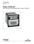
Model 1181 PB
Dissolved Oxygen Two-Wire Transmitter
ESSENTIAL INSTRUCTIONS
DANGER
HAZARDOUS AREA INSTALLATION
READ THIS PAGE BEFORE PROCEEDING!
Rosemount Analytical designs, manufactures, and tests
its products to meet many national and international
standards. Because these instruments are sophisticated
technical products, you must properly install, use, and
maintain them to ensure they continue to operate within
their normal specifications. The following instructions must
be adhered to and integrated into your safety program
when installing, using, and maintaining Rosemount
Analytical products. Failure to follow the proper
instructions may cause any one of the following situations
to occur: Loss of life; personal injury; property damage;
damage to this instrument; and warranty invalidation.
• Read all instructions prior to installing, operating, and
servicing the product. If this Instruction Manual is not
the correct manual, telephone 1-800-654-7768 and the
requested manual will be provided. Save this Instruction
Manual for future reference.
• If you do not understand any of the instructions, contact
your Rosemount representative for clarification.
• Follow all warnings, cautions, and instructions marked
on and supplied with the product.
• Inform and educate your personnel in the proper
installation, operation, and maintenance of the product.
• Install your equipment as specified in the Installation
Instructions of the appropriate Instruction Manual and
per applicable local and national codes. Connect all
products to the proper electrical and pressure sources.
• To ensure proper performance, use qualified personnel
to install, operate, update, program, and maintain the
product.
• When replacement parts are required, ensure that
qualified people use replacement parts specified by
Rosemount. Unauthorized parts and procedures can
affect the product’s performance and place the safe
operation of your process at risk. Look alike
substitutions may result in fire, electrical hazards, or
improper operation.
• Ensure that all equipment doors are closed and
protective covers are in place, except when
maintenance is being performed by qualified persons,
to prevent electrical shock and personal injury.
Emerson Process Management
Rosemount Analytical Inc.
2400 Barranca Parkway
Irvine, CA 92606 USA
Tel: (949) 757-8500
Fax: (949) 474-7250
http://www.RAuniloc.com
© Rosemount Analytical Inc. 2001
INTRINSICALLY SAFE INSTALLATION
Installations in hazardous area locations must
be carefully evaluated by qualified on site
safety personnel. Transmitter and Sensor
alone are not Intrinsically safe. To secure and
maintain an intrinsically safe installation, a
certified safety barrier must be used and the
installation must comply with the governing
approval
agency
(FM,
CSA
or
BASEEFA/CENELEC) installation drawing
requirements (see Section 2.0 - Installation).
EXPLOSION-PROOF INSTALLATION
Caution: Sensors are not explosion-proof. If the
sensor must be installed in a hazardous location
an intrinsically safe system must be
implemented.
To maintain the explosion-proof rating of the
transmitter, the following conditions must be
met:
• Discontinue power supply before removing
enclosure covers.
• Transmitter covers must be properly
installed during power on operation.
• Explosion proof "Y" fittings must be
properly installed with sealing compound
prior to applying power to the transmitter.
• Serial tag cover over the external Zero and
Span adjustments must be in place.
• See Installation Section for details.
Proper installation, operation and servicing of
this instrument in a Hazardous Area Installation
is entirely the responsibility of the user.
Model 1181 PB
TABLE OF CONTENTS
MODEL 1181 PB
TWO-WIRE TRANSMITTER
TABLE OF CONTENTS
Section
1.0
1.1
1.2
1.3
1.4
1.5
Title
DESCRIPTION AND SPECIFICATIONS .............................................
Features and Applications ....................................................................
Physical Specifications – General ........................................................
Performance Specifications – General .................................................
Performance Specifications at 25°C.....................................................
Ordering Information.............................................................................
Page
1
1
2
2
3
3
2.0
2.1
2.2
2.3
2.4
2.5
2.6
INSTALLATION ....................................................................................
Unpacking and Inspection ....................................................................
Mechanical Installation .........................................................................
Hazardous Locations-Explosion-Proof Installation ...............................
Wiring – General...................................................................................
Hazardous Locations-Intrinsically Safe Installation ..............................
Dissolved Oxygen Sensor ....................................................................
4
4
4
4
5
5
6
3.0
3.1
DESCRIPTION OF CONTROLS ..........................................................
Description of Controls .........................................................................
16
16
4.0
4.1
4.2
4.3
4.4
4.5
CONFIGURATION ...............................................................................
General.................................................................................................
Range Selection ...................................................................................
Course Span Adjustment......................................................................
External Zero and Span Adjustment.....................................................
Digital Display.......................................................................................
20
20
20
20
20
20
5.0
5.1
5.2
5.3
5.4
START UP AND CALIBRATION ..........................................................
General.................................................................................................
Transmitter Zero ...................................................................................
Air Calibration .......................................................................................
Calibration for Measuring ppb Oxygen .................................................
21
21
21
21
22
6.0
6.1
6.2
THEORY OF OPERATION ..................................................................
Model 1181 PB .....................................................................................
Dissolved Oxygen Measurement Sensor .............................................
23
23
24
7.0
7.1
7.2
DISASSEMBLY/REASSEMBLY PROCEDURE...................................
Disassembly Procedure........................................................................
Reassembly Procedure ........................................................................
26
26
26
8.0
8.1
8.2
8.3
TROUBLESHOOTING/MAINTENANCE ..............................................
General.................................................................................................
Troubleshooting....................................................................................
Maintenance .........................................................................................
27
27
27
28
9.0
9.1
SPARE PARTS ....................................................................................
Spare Parts...........................................................................................
31
31
10.0
10.1
10.2
10.3
RETURN OF MATERIAL......................................................................
General.................................................................................................
Warranty Repair ...................................................................................
Non Warranty Repair............................................................................
33
33
33
33
i
Model 1181 PB
TABLE OF CONTENTS
TABLE OF CONTENTS (CONT'D)
LIST OF FIGURES
Section
2-1
2-2
2-3
2-4
2-4
2-4
2-5
2-6
2-7
3-1
3-2
3-3
3-4
5-1
6-1
8-1
8-2
9-1
Title
Mounting and Dimensional Drawing.....................................................
Schematic System, FM Explosion Proof Approved ..............................
Transmitter Wiring ................................................................................
Schematic System, FM I.S. Approved - Entity (1 of 3) .........................
Schematic System, FM I.S. Approved - Entity (2 of 3) .........................
Schematic System, FM I.S. Approved - Entity (3 of 3) .........................
Schematic System, CSA I.S. Approved - Loop ....................................
Flow Chamber with Sensor Dimensions...............................................
Typical Installation with Siphon Breaker...............................................
Range Selector Switch and Course Span Adjust .................................
Display PCB .........................................................................................
External Zero and Span Adjust.............................................................
Digital Display.......................................................................................
Matrix Cover, Range Selection.............................................................
Simplified Block Diagram......................................................................
Recharge Kit.........................................................................................
Exploded View of Sensor/Membrane Assembly...................................
Model 1181 PB Two-Wire Transmitter Parts ........................................
Page
7
8
9
10
11
12
13
14
15
16
17
18
19
22
23
28
29
32
LIST OF TABLES
Section
8-1
9-1
Title
Troubleshooting Guide .........................................................................
Model 1181 PB Two-Wire Transmitter Spare Parts .............................
ii
Page
27
31
MODEL 1181 PB
SECTION 1.0
GENERAL DESCRIPTION AND SPECIFICATIONS
SECTION 1.0
DESCRIPTION AND SPECIFICATIONS
• TWO-WIRE FIELD MOUNTED TRANSMITTERS. Ideal for multiple loop installations where
central data processing and control are required. Field mounting near the sensor for ease in
routine calibration.
• NEMA 4X WEATHERPROOF, CORROSION-RESISTANT, DUAL COMPARTMENT HOUSING
provides maximum circuit protection for increased reliability in industrial environments.
• HAZARDOUS AREA INSTALLATION. Certified NEMA 7B explosion-proof and intrinsically safe
when used with an approved sensor and safety barrier.
• COMMONALITY OF PARTS reduces inventory required to support different field
measurements.
• SWITCH SELECTABLE RANGES further reduces inventory by permitting calibration of one
Model to virtually any Tag Number requiring the same measurement.
• EXTERNAL ZERO AND SPAN, 20-turn potentiometers provide for fine calibration of the
isolated 4-20 mA output signal.
1.1 FEATURES AND APPLICATIONS
The Rosemount Analytical Two-Wire PB Dissolved
Oxygen Transmitter, with the Model 120012 Dissolved
Oxygen Sensor Assembly, is used to accurately and
continuously measure dissolved oxygen at parts per
billion levels in applications such as boiler feed water,
food and beverage applications, deaerated sea water
for desalinization and deoxygenated brine for oil well
injection.
The Model 1181PB includes all the circuitry necessary
for the measurement and transmission of an isolated 420 mA signal. This current output signal is compatible
with, and provides a reliable front end measurement for,
virtually any process monitoring and control scheme.
The transmitter is housed in a NEMA 4 weatherproof,
NEMA 7 explosion-proof enclosure and is designed for
intrinsically safe operation. Features include external
20-turn ZERO and SPAN controls, and a dual
compartment housing with a moisture barrier that totally
isolates the electronic circuitry from the field wiring and
calibration terminals.
The electronic circuitry is mounted on printed circuit
boards (PCB’s) which plug directly into the moisture
barrier. The printed circuit boards are removed as a unit
and may be replaced individually or as a unit to expedite
maintenance.
The Model 1181PB is available with an analog meter, a
3¼ digit LCD display, or as a blind version if local
indication is not required. The measurement range is
field selectable and does not require removal of the
electronic circuitry. The range switch provides a full
scale span of 0-50, 0-100 or 0-200 PB, plus an air
calibrate position. A matrix is provided for convenient
indication of the proper switch position for a desired
measurement range.
The 3¼ digit LCD display can be calibrated for the
desired range using the “Display” zero and span pots
found on the LCD display board (these are not the same
as the “external” ZERO and SPAN controls), and the
decimal positioning switch, also located on the display
PCB. The display is directly proportional to the 4-20 mA
isolated current output. To facilitate installation, an
optional two-inch pipe/wall mounting bracket (Code 07)
is available.
The Model 120012 is a patented polarographic
dissolved oxygen sensor designed for long-life, high
accuracy and rugged use in industrial environments.
Constructed of Polypropylene and Teflon, the sensor
provides three to six months of continuous operation
before recharging, which simply involves adding a new
supply of liquid electrolyte and a new Teflon membrane.
To further reduce maintenance costs and down time, the
Teflon membrane is recessed for protection. Should it
become damaged, non-technical personnel can easily
replace it in a matter of minutes without concern for
variable tension, membrane stretching or folding.
The Model 120012 sensor comes with a Flow Chamber
Assembly, available only in PVC, that allows the sensor
to be mounted “inline”. The nozzle directs the sample
flow onto the cathode of the sensor. The direct
impingement of sample reduces sample flow
requirements. It also improves the response to changes
in dissolved oxygen while providing a cleaning action to
the sensor membrane.
1
MODEL 1181 PB
1.2 PHYSICAL SPECIFICATIONS –
GENERAL
Enclosure: NEMA 4X, weatherproof and corrosionresistant, NEMA 7B, explosion proof
Hazardous Area Classification - Explosion Proof:
FM: Class I, Groups B, C, & D, Div. 1
Class II, Groups E, F, & G, Div. 1
Class III
CSA: Class I, Groups C, & D
Class II, Groups E, F, & G
Class III, Encl 4
Class I, Groups A, B, C & D. Div. 2
Encl 4, Factory Sealed
Hazardous Area Classification - Intrinsic Safety:
FM: Class I, II & III, Div. 1
CSA: Class I, Groups A, B, C, & D
Encl 4, Temperature Code T4
SECTION 1.0
DESCRIPTION AN SPECIFICATIONS
Display:
Analog: plug in, 90 degree, 2.5 inch diameter
triple scale, 0-5, 0-10, 0-20 ppb X10
Digital: 3.5 digit, LCD, adjustable range in engineering units
Recommended Cable: Transmitter to Power Supply
Two Wire, 18 AWG, shielded, Belden 8760
or equal (Rosemount Analytical P/N 9200001)
Weight/Shipping Weight:
Blind: 1.44 kg/1.89 kg (3.18 lbs/4.18 lbs)
Analog/Digital: 2.15 kg/2.6 kg (4.74 lbs/5.75 lbs)
1.3 PERFORMANCE SPECIFICATIONS –
GENERAL
Power Supply Requirements: (See Load/Supply
Chart)
Lift Off Voltage:
Blind & Analog: 10 VDC
Digital: 12.5 VDC
Maximum Operating Power: 40 milliwatts
Output:
Blind & Analog: Isolated 4-20 mA into 700
ohms at 24 VDC
Digital: Isolated 4-20 mA into 575 ohms at 24 VDC
Input/Output Isolation: 600 Volts
Ambient Temperature: –30° to 70°C
Relative Humidity: 0-99%
Digital Display Accuracy: 0.1% reading ±1.0
count
Analog Display Accuracy: ±2.0%
External Zero: ±7.0% full scale (25% for 1181T)
External Span: ±7.0% full scale (50% for 1181T)
Shock: 10G maximum for 10 milliseconds
Vibration: 0.025 inches double amplitude
5 to 50 Hz for 2 hours
EMI/RFI:
EN61326
BLIND & ANALOG DISPLAY
LOAD/POWER SUPPLY REQUIREMENTS
+45 VDC @ 600 OHMS MIN. 1750 OHMS MAX.
1.8 –
1.7 –
1.6 –
1.5 –
1.4 –
1.3 –
1.2 –
1.1 –
1.0 –
0.9 –
0.8 –
0.7 –
0.6 –
0.5 –
0.4 –
0.3 –
0.2 –
0.1 –
0.0 –
10 VDC
LIFT OFF
1750 OHMS @
45 VDC
OPERATING
REGION
LOAD
RESISTANCE
REQUIRED
24 VDC
NOMINAL
33 VDC @ ZERO LOAD
45 VDC
MAXIMUM
POWER SUPPLY VOLTAGE
DIGITAL DISPLAY
LOAD/POWER SUPPLY REQUIREMENTS
+45 VDC @ 600 OHMS MIN. 1750 OHMS MAX.
1.8 –
1.7 –
1.6 –
1.5 –
1.4 –
1.3 –
1.2 –
1.1 –
1.0 –
0.9 –
0.8 –
0.7 –
0.6 –
0.5 –
0.4 –
0.3 –
0.2 –
0.1 –
0.0 –
12.5 VDC
LIFT OFF
1750 OHMS
@ 45 VDC
OPERATING
REGION
600 OHMS
@ 45 VDC
LOAD
RESISTANCE
REQUIRED
24 VDC
NOMINAL
35.5 VDC @ ZERO LOAD
POWER SUPPLY VOLTAGE
2
600 OHMS @
45 VDC
45 VDC
MAXIMUM
MODEL 1181 PB
SECTION 1.0
DESCRIPTION AN SPECIFICATIONS
The Model 1181PB Transmitter measures dissolved
oxygen in parts per billion. Switch selectable ranges are
0-50, 0-100, and 0-200 ppb with air calibrate.
RECOMMENDED SENSORS:
Rosemount Analytical, La Habra, CA :
Model 120012 (P/N 639900) Rechargeable
1.4 PERFORMANCE SPECIFICATIONS @ 25°C
Measurement Range: 0-50, 0-100, & 0-200 ppb
Accuracy: ±1.0% full scale
Stability: ±1.0% full scale/month, non-cumulative
Repeatability: ±1.0 full scale
Temperature Coefficient: ±0.05 %/°C
Automatic Temperature Compensation: 0-44°C
1.5 ORDERING INFORMATION
Model 1181 ppb DO Two Wire Transmitter is housed in a NEMA 7B explosion-proof, 4X weatherproof, corrosionresistant enclosure and includes all the circuitry necessary for measurement and transmission of an isolated 4-20 mA
signal. The transmitter may be selected with or without an analog or digital display.
MODEL
1181
TWO-WIRE TRANSMITTER
CODE INPUT (Required Selection)
PB Dissolved Oxygen ppb
CODE
01
02
06
DISPLAY (Required Selection)
Analog display
Blind, without indication
Digital display
CODE OPTIONS
07 Two-inch pipe/wall mounting bracket
11 Stainless steel nameplate (specify marking)
CODE
67
69
79
1181
PB
01
07-11
67
AGENCY APPROVALS
FM Explosion proof and Intrinsically Safe
CSA Explosion Proof and Intrinsically Safe
CE Construction (not available with Code 67 or 69)
EXAMPLE
NOTES:
Recommended cable from +24 volt DC power supply to Model 1181PB is Belden 8760, available from Irvine as P/N 920000; Specify length.
Model 1181PB is designed for use with Rosemount Analytical, La Habra, CA Sensor Model 120012 Rechargeable (P/N 639900) DO Sensor.
3
MODEL 1181 PB
SECTION 2.0
INSTALLATION
SECTION 2.0
INSTALLATION
2.1 UNPACKING AND INSPECTION. Before opening
the shipping carton, inspect the outside of the carton
for any damage. If damage is detected, contact the
carrier immediately. If there is no apparent damage,
open the carton and inspect the instrument and
hardware. Make sure all the items in the packing list
are present and in good condition. Notify the factory if
any part is missing. If the instrument appears to be in
satisfactory condition, proceed to the transmitter
installation.
NOTE
Save the original packing cartons and
materials as most carriers require proof of
damage due to mishandling, etc., also, if it
is necessary to return the instrument to the
factory, you must pack the instrument in
the same manner as it was received. (refer
to Section 10.0 for return of materials
instructions).
2.3 HAZARDOUS LOCATIONS-EXPLOSION
PROOF INSTALLATION. In order to maintain the
explosion proof rating for the installed transmitter, the
following conditions must be met:
1.
NOTE
These covers seat on o-rings which
serve to provide a dust proof
enclosure for Class II and Class III
installations.
2.
IMPORTANT
Do not attempt to install and operate the
Model 1181PB without first reading this
manual.
2.2.2 Mounting. The transmitter may be mounted on
a flat surface using the two threaded mounting holes
located on the bottom of the transmitter or through the
use of an optional 2-inch pipe/wall mounting bracket,
Code 07 (see Figure 2-1).
4
Explosion proof "Y" fittings must be properly
installed and plugged with a sealing compound to
prevent explosive gases from entering the
transmitter. CSA has determined that the
transmitter housing is "Factory Sealed". Installation of "Y" fittings and the use of sealing
compound is not required for CSA approved
Explosion Proof installations.
NOTE
Do not install sealing compound until
all field wiring is complete.
2.2 MECHANICAL INSTALLATION.
2.2.1 General. The transmitter may be installed in
harsh environments. However, it should be installed in
an area where sources of extreme temperature
fluctuation, vibration and shock are at a minimum or
non-existent. Select an installation site that (1) is
easily accessed by operating and maintenance
personnel; (2) is at least 12 inches (300 mm) from
sources of high voltage.
The transmitter enclosure covers must be on
hand tight and the threads must not be damaged.
CAUTION
Sealing compound must be installed
prior to applying power to the
transmitter.
3.
If one of the conduit connections on the housing
is not used, it must be closed with a threaded
metal plug with at least five threads engaged.
4.
The serial tag cover on the external ZERO and
SPAN adjustments must be in place.
5.
FM approved Explosion proof installation must be
in accordance with drawing number 1400155
(see Figure 2-2).
6.
Due to the nature of the measurement, sensors
cannot be designed to meet explosion proof
certification. If the sensors must be installed in
hazardous area locations, Rosemount Analytical
Inc. recommends that an intrinsically safe system
be installed.
MODEL 1181 PB
SECTION 2.0
INSTALLATION
2.4 WIRING-GENERAL. The transmitter is equipped
with two (2) ¼ -inch conduit openings, one on each
side of the housing. One is for the power supply/signal
wiring and the other is for the sensor wiring.
The use of waterproof cable glands or conduit is
recommended to prevent moisture from entering the
housing. If conduit is used, it should be positioned to
prevent condensation from draining into the housing.
It is recommended that the power cable/signal wiring
be shielded, twisted pairs that are earth grounded.
The transmitter case shall be grounded.
Signal or sensor wiring should never be run in the
same conduit or open tray with AC power or relay
actuated signal cables. Keep signal or sensor wiring
at least 12 inches from heavy electrical equipment.
NOTE
For best EMI/RFI protection the power
supply/signal cable should be shielded and
enclosed in an earth grounded, rigid metal
conduit. Connect the cable’s outer shield to
the transmitter’s earth ground terminal near
TB1, Fig. 2-3.
The sensor cable should also be shielded.
The cable’s outer shield shall be connected to
the transmitter’s earth ground per the
instructions above. If the sensor’s outer shield
is braided, an appropriate metal cable gland
fitting may be used to connect the braid to
earth ground via the instrument case.
A new addition to the suite of tests done to
ensure CE compliance is IEC 1000-4-5. This
is a surge immunity test that simulates
overvoltages due to switching and lightning
transients.
In order to meet the requirements of this test,
additional protection must be added to the
instrument in the form of a Transient Protector
such as the Rosemount Model 470D. This is a
3½-inch tube with ½-inch MNPT threads on
both ends. Inside the tube are gas discharge
and zener diode devices to limit surges to the
transmitter from the current loop. No
additional protection is needed on the sensor
connections.
2.4.1 Sensor Wiring. The Sensor wiring terminals are
located on the side of the housing designated TERM
SIDE on the serial label. Remove the housing cover
from the TERM SIDE to gain access to the terminals
designated TB2. Remove the optional Analog or
Digital display. The plug in analog display is held in by
a spring clip and the digital display is held in by a
locking screw. Connect the sensor wiring to TB2
terminals 1 through 4 as shown in Figure 2-3.
The Model 120012 dissolved oxygen sensor is
connected to the 1181 transmitter via a six (6)
conductor cable (PN 70000-04) as shown in Figure 2-3.
Prepare the unfinished (transmitter) end of the sensor
cable, as shown in Figure 2-3, then wire the sensor to
the transmitter per the following Steps:
1.
Connect the connector end of the cable to the PB
sensor.
2.
Ensure that the transmitter end of the cable has
been properly prepared with the green and yellow
wires removed and spade lugs attached. Insert
the cable through the conduit opening opposite
the external zero and span screws. This side
MUST be used due to the large size of the cable.
2.4.2 Power and Signal Wiring. The power and
signal wiring terminals are located directly above
the Sensor wiring terminals and are designated
TB1 (see Figure 2-3). TB1 also provides for
plugging in the optional Analog display or wiring
of the optional digital display.
2.5 HAZARDOUS LOCATIONS-INTRINSICALLY
SAFE INSTALLATION. To secure and maintain
intrinsically safe installation for the appropriate
approval agency, the following conditions must be
met:
1.
Code 67 must be specified when ordering F.M.
units. Approved “Entity” installation must be in
accordance with Drawing Number 1400153 (see
Figure 2-4).
2.
Code 69 must be specified when ordering CSA
(Canadian Standards Association) units.
Installation must be performed in accordance with
Drawing Number 1400157 (see Figure 2-5).
5
MODEL 1181 PB
2.6 DISSOLVED OXYGEN SENSOR. The sensor
should be installed in San environment where the
temperature remains between 0 and 44°C (32-110°F).
It is used in combination with the 627866 flow
chamber and should be mounted as described in the
following sections.
2.6.1 Installation Procedure. The sensor is shipped
assembled and charged, ready for use. Occasionally,
however, a new sensor may perform unsatisfactorily
upon initial start-up, because of previous long storage
or other unusual circumstances. If this occurs, the
sensor must be recharged as explained in Section 8.3.
During subsequent routine operation, the sensor will
require periodic recharging, typically about once every
three months. Outline and mounting dimensions of the
flow chamber are given in Figure 2-6.
2.6.2 Monitoring Boiler Feedwater or Other HighPurity Water. The flow chamber may be mounted
behind the panel of a water quality system, or in the
plant, near the sample point.
1.
Mount the flow chamber horizontally, with the
outlet port facing upward. Thus, upon start-up,
any gas bubbles will be rapidly purged. Mounting
the flow chamber horizontally also prevents
entrapment of gas bubbles on the surface of the
sensor membrane.
2.
A siphon-breaker vent should be installed in the
outlet line so that the flow chamber will remain full
of water during boiler shutdowns (see Figure 2-7).
3.
The sensor is installed in the flow chamber with
adaptor (P/N 193523) and safety clamp (see
Figure 2-6).
4.
Sample Temperature and Flow Requirements.
Preferably, the flow chamber should receive
sample that has been temperature-conditioned to
25°C ±1°C. If this is not possible, use watercooled sample with the temperature held constant
to ±5°C.
6
SECTION 2.0
INSTALLATION
2.6.3 Monitoring Deaerated Sea Water. In the multistage flash vaporization process for desalinization of
sea water, feedwater is deaerated prior to entry into
the evaporators. Because of the highly corrosive
effect of oxygenated sea water, the deaeration
efficiency should be monitored continuously.
Installation of the flow chamber is essentially the
same as for monitoring boiler feedwater, as described
in Section 2.6.2.
2.6.4 Monitoring Deoxygenated Brine for Oil Well
Flooding. In oil well flooding, large volumes of brine
are pumped underground to replace oil and brine
removed during the oil production operation.
To prevent excessive corrosion of equipment, the
brine is deoxygenated prior to pumping underground.
Use of the Model 1181PB DO is essentially the same
as the boiler feedwater and desalinization applications
previously described. However, the brine may contain
metallic sulfides which may form a coating on the
oxygen sensor, thus requiring more frequent sensor
maintenance than in the other applications.
A typical sampling system is shown in Figure 2-7.
Sample for the flow chamber is obtained via a tap in
the piping on the discharge side of the flooding pump.
A needle valve is used to regulate sample flow.
Installation of a flowmeter in the sample line is usually
impractical because of the coating problem. Instead,
flow is measured by allowing the discharge from the
chamber to flow into a graduated cylinder for a timed
interval. Recommended flow rate is approximately 500
milliliters per minute.
MODEL 1181 PB
SECTION 2.0
INSTALLATION
FIGURE 2-1 Mounting and Dimensional Drawing
7
DWG. NO.
FIGURE 2-2. Schematic System, F.M. Explosion Proof Approved
8
C
REV.
SECTION 2.0
INSTALLATION
1400155
MODEL 1181 PB
MODEL 1181 PB
SECTION 2.0
INSTALLATION
Power Wiring (TB1)
TB1-1, Loop Signal [Power Supply (+)VDC]*
TB1-2, Meter (+) Red
TB1-3, Loop Signal [Power Supply (-) VDC]* /Meter (-)
* 4-20 mADC
Sensor Wiring (TB2)
TB2-1 TC Element (Brown)
TB2-2 Shield
TB2-3, Gold Cathode (Black) and T. C. Element (Blue)
TB2-4, Silver Anode (Red)
Note: The white and green wires of the sensor cable are not used
and should be cut back away from the terminal connections of the
1181.
FIGURE 2-3. Transmitter Wiring
9
MODEL 1181 PB
SECTION 2.0
INSTALLATION
FIGURE 2-4. Schematic System, F.M. I.S. Approved-Entity (1 of 3)
10
MODEL 1181 PB
SECTION 2.0
INSTALLATION
FIGURE 2-4. Schematic System, F.M. I.S. Approved-Entity (2 of 3)
11
MODEL 1181 PB
SECTION 2.0
INSTALLATION
FIGURE 2-4. Schematic System, F.M. I.S. Approved-Entity (3 of 3)
12
DWG. NO.
1400157
ANY CHANGE TO THIS DRAWING MAY AFFECT CSA APPROVAL
1.
NOTES: UNLESS OTHERWISE SPECIFIED
SENSOR ASSEMBLIES IN THIS SYSTEM ARE LOW ENERGY NON INCENTIVE DEVICES WHICH DO
NOT CONTAIN MAKE/BREAK CONTACTS OR COMPONENTS WHICH PRODUCE OR STORE MORE
THAN 1.2V, 0.1A, 25mW OR 20 µJ.
APPROVED FOR CLASS 1, DIVISION 1, GROUPS C & D WHEN USED IN CIRCUIT WITH TWO CSA
CERTIFIED SINGLE CHANNEL SAFETY BARRIERS (OF LIKE POLARITY), ONE WITH APPROVED SAFETY
PARAMETERS OF 30 VOLTS OR LESS AND 150 OHMS OR MORE IN PLUS POWER LINE, AND ONE WITH
APPROVED SAFETY PARAMETERS OF 10 VOLTS OR LESS AND 47 OHMS OR MORE IN PLUS
OUTPUT LINE.
APPROVED FOR CLASS 1, DIVISION 1, GROUPS A, B, C, D WHEN NOT USED IN CIRCUIT WITH TWO CSA
CERTIFIED SINGLE CHANNEL SAFETY BARRIERS (OF LIKE POLARITY) ONE WITH APPROVED SAFETY
PARAMETERS OF 28 VOLTS OR LESS AND 300 OHMS OR MORE IN PLUS POWER LINE, AND ONE WITH
APPROVED SAFETY PARAMETERS OF 10 VOLTS OR LESS AND 47 OHMS OR MORE IN PLUS OUTPUT
LINE.
2.
3
s
B
u
MODEL 1181 PB
SECTION 2.0
INSTALLATION
REV.
B
FIGURE 2-5. Schematic System, CSA I.S. Approved-Loop
13
MODEL 1181 PB
SECTION 2.0
INSTALLATION
FIGURE 2-6. Flow Chamber with Sensor Dimensions
14
MODEL 1181 PB
SECTION 2.0
INSTALLATION
FIGURE 2-7
. Typical Installation with Siphon Breaker
15
MODEL 1181 PB
SECTION 3.0
DESCRIPTION OF CONTROLS
SECTION 3.0
DESCRIPTION OF CONTROLS
3.1 DESCRIPTION OF CONTROLS.
3.1.1 Range Selector Switch. A set of five (5) dip
switches used for selecting the 1181PB measurement
ranges (0-50, 0-100, 0-200PB). The Air Calibrate
position is used during Start Up, Periodic Maintenance
or Troubleshooting (see Figure 3-1).
3.1.2 Coarse Span Adjust. A 280° printed circuit
board mounted potentiometer used for coarse
adjustment of the operating range for the 1181
transmitter (see Figure 3-1).
3.1.3 Analog/LCD Operation Jumper located on
the transmitter display PCB. When the jumper is in
the W5 position (• n n) position, the 1181PB will
operate only with an analog meter or as a blind unit.
But when the jumper is in the opposite position (nn •)
or is removed, the 1181PB will operate only with an
LCD (see Figure 3-2).
3.1.4 External Zero Adjust. A 20-turn potentiometer for
fine tuning the low end current output value with respect
to the low end of the measurement range selected by the
Range Selector Switches (see Figure 3-3).
3.1.5 External Span Adjust. A 20-turn potentiometer
for fine tuning the full scale current output value with
respect to the full scale value of the measurement
range selected by the Range Selector Switches (see
Figure 3-3).
3.1.6 LCD Zero and Span. Printed circuit board
mounted potentiometers for adjustment of the LCD
display. The display can be adjusted for any value from 0
to 1999 (see Figure 3-4).
3.1.7 LCD Decimal Point Switch. Switch for selection
of the decimal point location on the LCD display (see
Figure 3-4).
DWG. NO.
32968-00
FIGURE 3-1. Range Selector Switch and Course Span Adjust
16
REV.
A
MODEL 1181 PB
SECTION 3.0
DESCRIPTION OF CONTROLS
FIGURE 3-2. Display PCB
17
MODEL 1181 PB
SECTION 3.0
DESCRIPTION OF CONTROLS
FIGURE 3-3. External Zero and Span Adjust
18
MODEL 1181 PB
SECTION 3.0
DESCRIPTION OF CONTROLS
FIGURE 3-4. Digital Display
19
MODEL 1181 PB
SECTION 4.0
CONFIGURATION
SECTION 4.0
CONFIGURATION
4.1 GENERAL The Model 1181PB is factory calibrated
to measure 0-200 ppb dissolved oxygen corresponding
to a 4-20 mA. The optional LCD display is calibrated to
0-100% corresponding to 4-20 mA.
4.5 DIGITAL DISPLAY. The digital display is factory
calibrated to indicate 0-100% corresponding to 420mA and is provided with independent zero and
span potentiometers.
NOTE
Do not attempt to adjust any sealed
adjustment pots.
The LCD is a three and a half digit display and may be
calibrated in engineering units (ppb DO) to indicate
from 000 to 1999.
4.2 RANGE SELECTION. The sequence for changing
the full scale measurement of the Model 1181PB is
shown on a range matrix opposite the range switch
block (see Figure 3-1). The matrix is accessed by
removing the housing cover on the circuit side of the
transmitter.
The first three columns of the range matrix identifies
each range switch position (on or off) to accommodate
the desired full scale measurement range or for air
calibration. For example, if a 0-50 ppb full scale
measurement range is desired, reading vertically on
the range matrix, switches 1 thru 5 should be closed
and switch 1 should be open.
4.3 COARSE SPAN ADJUSTMENT. The course span
adjustment 1 turn potentiometer should be set at mid
range before start-up procedures (see Figure 3-1).
4.4 EXTERNAL ZERO AND SPAN ADJUSTMENT.
These 20-turn potentiometers should be set at mid
range before commencing start-up proceedures (see
Figure 3-3).
20
A decimal point switch is provided and may be
accessed by removing three cover screws and the
cover. The decimal point switch is located below and
to the right of the LCD display. The dip switches are
designated s1, s2, and s3. The decimal point
adjustment is as follows:
Decimal Point Position
s1
s2
s3
1999
open
open
open
199.9
open
open
closed
19.99
open
closed
open
1.999
closed
open
open
To calibrate the LCD display, adjust the zero
potentiometer for 000 at 4.0 mA output and the span
potentiometer for the full scale (ppb DO) range at 20.0
mA output.
MODEL 1181PB
SECTION 5.0
START UP, AND CALIBRATION
SECTION 5.0
START UP AND CALIBRATION
5.1 GENERAL. This section provides the start-up and
calibration procedure for the Model 1181PB two-wire
transmitter. The Transmitter is used in conjunction
with the PB sensor assembly.
5.3 AIR CALIBRATION. To initially calibrate the
Transmitter/Sensor loop for response oxygen partial
pressure, use the following procedure:
1.
Expose the sensor to ambient air. The membrane
must be clean and dry. Inspect the membrane for
splits, tears, wrinkles or any obvious damage.
Make sure there is no oil or solvent coating on the
membrane.
2.
nitrogen gas, or fresh water sparged with nitrogen gas
should be used for zeroing.
Remove the cover from the circuit side of the
transmitter housing.
3.
Set RANGE SWITCH to the AC (Air Calibrate)
position (see Figure 5-1).
1.
Make sure the transmitter and sensor are
installed and wired as specified in Sections 2.0
and 3.0 and that the sensor is completely dry,
then apply power to the transmitter.
4.
Allow sufficient time (up to 60 minutes) for the
sensor to reach temperature equilibrium with the
air.
5.
2.
Remove the covers from the transmitter housing.
Once the reading is stable, adjust the EXTERNAL
SPAN control to the minimum reading.
3.
Place the RANGE SWITCH in the 50 ppb range
position (see Figure 5-1).
4.
Place sensor in zero DO solution and allow it to
remain there for 12 to 24 hours before
proceeding.
5.2 TRANSMITTER ZERO. This procedure is required
to electronically zero the transmitter/sensor loop. In
order to eliminate any residual current in the sensor it
must be placed in a zero DO solution and remain
there for a minimum of 12 to 24 hours before adjusting
the transmitter zero. 2% sodium bislfite (NaHSO3),
5.3.1 Air Calibration Adjustment for Transmitters
with Analog Meters (Code 01).
1.
5.2.1 Zero Adjustment for Transmitters with
Analog Meter (Code 01). Adjust the external zero
control of the Transmitter to obtain a 4.0 mA output
and a zero meter indication of zero.
5.2.2 Zero Adjustment for Transmitters with LCD
Digital Display.
1.
Adjust the external zero control of the Transmitter
to obtain a 4.0 mA output.
2.
Adjust the zero adjustment on the Digital LCD
Display to indicate zero.
Adjust the COURSE SPAN ADJUST pot (see
Figure 5-1) to a reading on the 0-100 ppb scale
on the Analog Meter, which equals 1/ 10 of the
local barometric pressure in millimeters of
Mercury (mmHg).
NOTE
1 inch Hg = 25.4 mmHg
1 mmHg = 0.133 kPa
EXAMPLE: If the barometric pressure reading,
obtained from your local weather station or airport,
equals 30.16 in Hg then:
(30.16 in Hg) X (25.4 mmHg
in H2 ) = 766 mmHg
The reading on the Analog Meter's 0-100 ppb scale
would then adjusted to 1/10 of 766 or 76.6.
2.
If required, adjust the External SPAN control to
obtain the exact Analog METER indication.
3.
Set Range Switch to the desired a range.
4.
Install Sensor into the flow chamber and allow the
system to purge 12 to 24 hours.
21
MODEL 1181PB
SECTION 5.0
START UP, AND CALIBRATION
5.3.2 Air Calibration Adjustment for Transmitters
with LCD Digital Display (Code 06).
1.
Adjust the COURSE SPAN ADJUST POT (see
Figure 5-1) to obtain a transmitter output
calculated from the local barometric pressure as
follows (see note in Section 5.3.1 on converting
barometric pressure in inches of mercury (inHg)
to millimeters of Mercury (mmHg):
Barometric Pressure (mmHg)
Output(mA) = __________________________ + 4.0
62.5
2.
If required, adjust the EXTERNAL SPAN control
to obtain the exact milliamp output.
3.
Adjust the LCD DIGITAL DISPLAY by adjusting
the SPAN ADJUST on the DIGITAL DISPLAY to
indicate the following ppb concentration, based
on the desired operating range in ppb:
Desired Operating
Range
________________
Adjust LCD Digital
Display
Span to Read:
____________________
5.4 CALIBRATION FOR MEASURING PPB OXYGEN
The final calibration adjustment takes into account the
actual solubility of oxygen in the process. Adjustment
is made based on chemical analysis of a process grab
sample. Sampling procedures and the method of
analysis will depend upon the current procedure used
for a particular application, such indigo carmen
analysis for boiler feed, or US Department of the
Interior methods for deaerated sea water, etc.
In any case, final calibration should be performed only
when the process is in a steady state conditions, and
not during upsets or when oxygen concentrations are
rapidly fluctuating.
1.
Note the reading on the Analog Meter or LCD
Digital Display at the time the grab sample is
taken.
2.
If the reading on the Analog Meter or Digital
Display has not changed after the analysis has
been completed, adjust the External span adjust
pot to match the analysis. The transmitter/sensor
loop is now calibrated.
3.
If the reading on the Analog Meter or Digital
Display has changed since the grab sample was
taken, adjust the external span adjust pot to
obtain a ppb reading as calculated below:
Barometric Pressure (mmHg)
20
0-50 ppb
ppb =____________________
0-100 ppb
ppb =____________________
0-200 ppb
ppb =____________________
Barometric Pressure (mmHg)
10
Barometric Pressure (mmHg)
5
The digital LCD display is now calibrated.
4.
Set the RANGE SWITCH to the desired operating
range.
5.
Install the sensor into the flow chamber and allow
the system to purge 12 to 24 hours.
Adjust Reading to:
ppb =
Concentration
by lab analysis
______________
X Present Reading
Reading at time
of sampling
The Transmitter/Sensor loop is now calibrated.
FIGURE 5-1. Matrix Cover-Range Selection
22
MODEL 1181 PB
SECTION 6.0
THEORY OF OPERATION
SECTION 6.0
THEORY OF OPERATION
6.1 MODEL 1181PB. The Model 1181PB Two-Wire
Transmitter automatically and continuously measures
low-level concentrations of dissolved oxygen in water
or aqueous solutions. The determination is based on
the measurement of the electrical current developed
by the dissolved oxygen measurement sensor in
contact with the sample. This theory of operation is
illustrated below (see Figure 6-1 Simplified Block
Diagram).
6.1.1 Liftoff Voltage. The transmitter lifts off
approximately 10 volts from the loop current to power
the electronics. The voltage dropped across VR1
provides for the system voltage. Upon start-up, a
voltage potential must be established across VR1 to
power the power supply (P.S.) module. To establish
this voltage, a starting current is generated by current
diode CR1 (Q1 and Q2 are off during start-up). Once
the power supply module is started, power is provided
for AR1 and then 1 and 2 are switched on to regulate
the current loop current.
6.1.2 Power Supply Module.The power supply
module on the loop-side switches at 10K Hz to
provide ±5 volts power for the sensor-side power
supply module, and ±5 volts power for the loop-side
module. The power supply mode also provides
modulator and demodulator chopping signals. On the
sensor-side a polar voltage is generated for the
sensor electrodes and the resultant current is scaled.
6.1.3 Temperature Compensation Circuit. The
dissolved oxygen measurement of a solution varies
with temperature change. Change in temperature is
sensed at the sensor and is automatically corrected to
a reference temperature of 25°C.
6.1.4 Output Signal. After the signal is corrected for
the temperature, it is then modulated across the
isolation transformer and receiver by amplifier AR1,
where it is generated as a current proportional to the
modulated signal plus four milliamps. Diode CR2
protects against reverse current flow, and CR3 and
CR4 are meter diodes.
FIGURE 6-1. Simplified Block Diagram
23
MODEL 1181 PB
6.2 DISSOLVED OXYGEN MEASUREMENT SENSOR
Rosemount Analytical utilizes the amperometric
membrane technique for the measurement and
control of dissolved oxygen. The success of
membrane electrodes stems from the isolation of the
electrodes (cathode and anode) and electrolyte from
the sample by means of a semi-permeable
membrane. This membrane protects the electrodes
from contamination by restricting the flow of sample to
gases only, and oxygen in particular.
Within the body of the sensor is a gold cathode and a
silver anode, electrically connected by potassium
chloride (KCL) electrolyte solution and separated from
the process stream by a gas permeable membrane.
The transmitter lifts off at approximately 10 VDC from
the loop current to power the electronics and, in turn,
supplies a constant 750mV DC polarizing voltage
which is impressed across the two electrodes.
Oxygen from the sample diffuses through the
membrane and is reduced at the gold cathode. The
resultant electrical current flow between anode and
cathode is proportional to the partial pressure of
oxygen in the sample. The chemical reactions which
accompany this process are as follows
Gold cathode: O2 + 2H2O + 4e- Ê 4OHSilver anode: 4Ag + 4C1- Ê 4AgC1 + 4eThe reaction that takes place at the anode is the
oxidation of silver to form silver chloride. This reaction
is offset at the gold cathode by the reduction of
oxygen molecules to hydroxide ions. The resulting
current is directly proportional to the dissolved oxygen
content of the sample stream.
24
SECTION 6.0
THEORY OF OPERATION
A 30K thermistor incorporated in the sensor, is used
by the 1181PB transmitter to; (1) compensate for
temperature-dependent variations in the permeability
of the membrane to oxygen and (2) to compensate for
temperature-dependent variations in the solubility of
oxygen in water.
During installation, the sensor is mounted in the flow
chamber. Within the chamber, the sample passes
through a nozzle and impinges directly onto the
membrane area of the sensor. This arrangement permits
fast response with comparatively low sample flow.
6.2.1 Measurement Variables. Variables that
influence the dissolved oxygen measurement include
barometric pressure, relative humidity, sample
temperature, interfering gases and composition of the
liquid medium.
6.2.2 Barometric Pressure and Relative Humidity.
Rate of oxygen diffusion through the sensor
membrane, and therefore the sensor response, is
linear with respect to oxygen partial pressure
(assuming constant sample temperature).
At the normal sea-level barometric pressure of 760
mm Hg (101.3 kPa), the oxygen partial pressure of dry
air is 160 mm Hg (21.2 kPa). As atmospheric pressure
deviates from the standard value, the oxygen partial
pressure varies proportionally. Accordingly, the
solubility of oxygen in water varies in proportion to the
change in the partial pressure of oxygen in air.
Barometric pressure is therefore a significant factor
instrument calibration.
6.2.3 Relative Humidity. In calibration for dissolved
oxygen measurement, one method is to expose the
sensor to a gaseous sample, typically dry air, of
accurately known oxygen content. The known
gaseous oxygen concentration value is the related to
a corresponding dissolved oxygen value.
MODEL 1181 PB
SECTION 6.0
THEORY OF OPERATION
Since dry air contains 20.95 oxygen by volume,
regardless of the barometric pressure, the partial
pressure of oxygen can be shown to be directly
proportional to the total barometric pressure,
according to Dalton’s law of partial pressures. Thus
for dry air, if the total barometric pressure is known,
the partial pressure of oxygen can be computed.
However, this procedure is valid only for dry air
conditions. Humid air has the effect of reducing the
partial pressure of oxygen and the other gases in the
air without affecting the total barometric pressure.
Another way of expressing this relationship is by the
following equation:
where P(atm)
= P(gas) + P(oxygen + P(water)
P(atm)
= Total barometric pressure
P(gas)
= Partial pressure of all gases other
than oxygen and water vapor
P(oxygen) = Partial pressure of oxygen
P(water)
= Partial pressure of water vapor
Thus, for constant barometric pressure, if the humidity
in the air is other than zero, the partial pressure of
oxygen is less than the value for dry air. For most
measurements taken below 80°F (26.7°C), the effect
of water vapor may be ignored.
To determine the partial pressure of oxygen in air at
various levels of humidity and barometric pressure,
the partial pressure of water is subtracted from the
total barometric pressure and the difference is
multiplied by 20.95%.
EXAMPLE:
Barometric pressure = 740 mm Hg (98.5 kPa)
Partial pressure H2O = 20 mm Hg (2.7 kPa)
Partial pressure O2
=70-20] x 0.2095 mm Hg
= 150 mm Hg (19.95 kPa)
6.2.4 Sample Temperature. The temperature of the
sample affects sensor response in two ways:
1.
2.
Oxygen Solubility -- In an oxygen-saturated
liquid, partial pressure of dissolved oxygen is
equal to the partial pressure of oxygen in the
atmosphere above liquid. This relationship holds
true regardless of the oxygen concentration in
parts per billion by weight. As sample
temperature increases, oxygen partial pressure
remains unchanged (except as influenced by
Vapor pressure of the liquid); however, the
dissolved oxygen concentration in parts per billion
by weight is reduced.
To compensate for both temperature affects the
Model 1181PB uses the 30K thermistor incorporated
in the measurement sensor. As the sample temperature changes, the thermistor resistance also changes
affecting the signal gain of the transmitter. The result
is a temperature corrected dissolved oxygen reading
in parts per billion within the range of 32°F to 110°F
(0°C to 44°C) .
6.2.5 Interfering Gases. Gases that are reduced or
oxidized at about 0.75 Vdc, and thus contribute to
sensor current, may cause a readout error. Only a few
gases have this characteristic. Common gases that
should be avoided include S0 2, C12 and oxides of
nitrogen. Low-level concentrations of hydrogen-sulfide
tend to contaminate the sensor, but do not seriously
affect dissolved oxygen measurement. If
contaminated, the sensor must be rejuvenated by
procedures described in Section 8.3.2.
6.2.6 Composition of the Liquid Medium. A
significant change in the composition of the solution
may change the solubility of oxygen. If the solvent is
water, the addition of any water soluble components,
such as sodium chloride, may change the dissolved
oxygen concentration.
If the water contains chlorides for example, the
reading will be corrected to take into account the
effect of the chlorides by the final grab sample
calibration (see Section 5.4).
Oxygen Diffusion Rate -- The rate of oxygen
diffusion through the sensor membrane varies
with temperature at a coefficient of about +3% per
degree Celsius, causing a corresponding change
in sensor current.
25
MODEL 1181PB
SECTION 7.0
DISASSEMBLY/ASSEMBLY PROCEDURE
SECTION 7.0
DISASSEMBLY/REASSEMBLY PROCEDURE
7.1 DISASSEMBLY PROCEDURE. Disconnect the
power to the transmitter prior to disassembly. (see
Figure 9-1 for item numbers also see Figure 3-3).
1.
Remove covers (1) and (14) or meter housing
cover (11) from housing (3). Save O-rings (2);
discard if damaged.
2.
Loosen screws retaining the serial label, and then
rotate to gain access to the Span and Zero pots.
3.
Align the Span and Zero adjusting screws (4), so
the slots are horizontal, pointing end cap to end
cap.
4.
In circuit side of housing (3) remove the circuit
board retaining screws, washers and matrix cover
(10). The matrix cover is secured to screws by
nylon split washers. Remove the screws in equal
increments, so the matrix cover is not damaged.
5.
Pull straight out on the signal conditioning board
assembly (9) to remove circuit boards from
housing (3).
6.
To separate the individual boards, remove the
retaining screw located on the terminal side of the
transmitter board (6).
7.
Remove each printed circuit board assembly by
pulling straight out from their respective
connectors.
26
7.2 REASSEMBLY PROCEDURE.
1.
Assemble the circuit board assemblies (6,7,8,9)
by first aligning the connectors with the respective
pins, and then pushing straight in. Install screw
which holds circuit board assemblies together.
2.
Align the Zero and Span adjusting screws (4) on
the housing (3) to the horizontal position, slots
pointing end cap to end cap (see Figure 3-3).
3.
Align the Zero and Span potentiometers (R29 &
R23) located on the driver circuit board (7) to the
horizontal position, with blades perpendicular to
PCB's (6) and (7) (see Figure 9-1).
4.
Place the circuit board assemblies (6, 7, 8, 9) into
housing by first aligning the connector pins with
the terminal receptacles in the base of the
housing (3) and then pushing straight in on the
signal conditioning board (9).
5.
Install the matrix cover (10) and secure with
screws and washers. The matrix cover is secured
to the screws with nylon split washers, so install
the screws in equal increments, so the matrix
cover is not damaged.
6.
Inspect the thread connections on housing (3) to
make sure five undamaged threads will fully
engage.
7.
Replace O-rings (2) on housing (3). Use new Orings if the old ones were damaged.
8.
Install covers (1,14) or meter housing (11) on
transmitter housing (3).
9.
Apply power to the transmitter and perform the
appropriate calibration procedure if necessary.
MODEL 1181 PB
SECTION 8.0
TROUBLESHOOTING/MAINTENANCE
SECTION 8.0
TROUBLESHOOTING/MAINTENANCE
8.1 GENERAL. This section covers the troubleshooting and maintenance instructions for the Model
1181PB Transmitter and PB DO Sensor. The
transmitter has no moving parts and requires
minimum maintenance. Procedures for calibrating the
Model 1181PB is given in Section 5.0 and generally
the only operation type "maintenance" required to
keep the units in good operating condition.
NOTE
If downtime is of critical concern, a full
complement of spare parts is recommended. (See Section 9.0, spare parts).
8.2 TROUBLESHOOTING. Table 8-1 provides a
general reference table for commonly encountered
problems and suggested actions to be taken to correct
those problems.
TABLE 8-1. Troubleshooting Guide
SYMPTOM
1. Abnormally high O2
readings (inability to
calibrate)
PROBLEM
ACTION
a. Hole in membrane
Replace membrane
b. Gold cathode loose
Replace sensor
c. Open thermistor
Replace sensor
a. High internal cell resistance
Rejuvenate and recharge cell
b. Membrane too loose
Tighten cap or replace membrane
c. Contaminated electrolyte*
Clean sensor and recharge
d. Shorted thermistor
Replace sensor
a. Membrane loose
Replace sensor
b. Low electrolyte level
Fill properly
c. Cathode contaminated*
Rejuvenate and recharge
4. Upscale readings with known
oxygen-free sample
a. Gold cathode loose
Replace sensor
5. Slow response (sluggish)
a. Contaminated electrolyte*
Rejuvenate and recharge
2. Abnormally low O2 readings
(inability to calibrate)
3. Sensor noisy (motion sensitive)
* Contamination” may be the normal accumulation from long-term operation, indicating standard rejuvenation is required.
27
MODEL 1181 PB
SECTION 8.0
TROUBLESHOOTING/MAINTENANCE
8.3 MAINTENANCE. Most routine maintenance
involves the sensor. Sensor maintenance consists of
periodic recharging and-cleaning, or rejuvenating the
sensor cathode. The usual indication that the sensor
requires rejuvenation and recharging is that, during
calibration, the correct upscale reading is unobtainable
by adjustment of the EXTERNAL SPAN CONTROL.
Normally, the inability to calibrate is preceded by a
gradual, day-to-day reduction in sensor output, with a
resultant lower instrument indication. The rate of
reduction increases with the increase in internal
resistance of the sensor.
NOTE
If the sensor is disassembled for inspection,
it must be recharged, utilizing a new
membrane.
Normally, the sensor requires recharging with fresh
electrolyte once every three months. Cleaning the
sensor and rejuvenating the electrodes may be
extended to longer intervals, depending on the
application in which the sensor is used. In general,
correcting a low output may be accomplished by first
recharging with fresh electrolyte, as described in
Section 8.3.1.
8.3.1 Recharging The Sensor. The sensor must be
removed from the process installation for recharging. A
recharge kit, Figure 8-1, provides the necessary
materials for recharging. Fresh electrolyte, a new Teflon
membrane, and a pressure-compensating rubber
diaphragm must be placed in the sensor. The following
steps describe how to recharge the sensor.
1.
2.
3.
Unscrew the knurled cap from end of sensor body.
Remove membrane assembly, consisting of Teflon
membrane fixed between holder and retainer (see
Figure 8-2). Empty all the electrolyte from sensor
and flush with distilled or deionized water to remove
all particulate matter.
Unscrew the fill-port plug. Remove the Teflon
washer and pressure-compensating diaphragm
from the fill port .
Examine the gold cathode for the following:
a. Staining or uneven coloration indicates that the
cathode should be rejuvenated as described in
Section 8.3.2.
b. Any deposited material (typically white to gray)
present in or around the grooves of the cathode
must be removed to ensure optimum operation.
Most of these deposits are water-soluble and may
be removed by a water jet from a squeeze bottle.
Any insoluble deposits in the annular and channel
grooves may be removed with a toothpick, taking
care to avoid deforming the grooves.
Figure 8-1. Recharge Kit
28
MODEL 1181 PB
4.
5.
6.
SECTION 8.0
TROUBLESHOOTING/MAINTENANCE
The membrane assembly consists of a Teflon
membrane and three associated parts: a holder,
a retainer, and an O-ring. Remove the retainer
from the holder by placing a finger into center
hole of holder and pressing the fingernail against
the inner edge of retainer .
Verify that the O-ring is properly positioned in the
associated groove in the holder (see Figure 8-2).
Holding a single Teflon membrane, by the edges
only, place it across the membrane holder; then,
snap the retainer into the membrane holder (see
Figure 8-2). The membrane is now fixed in the
proper position, between the holder and retainer.
CAUTION
Never touch the center area of the
membrane with your fingers. Membranes
are easily contaminated with foreign
substances. Contaminated membranes
cause drifting or erratic readings.
7. Using a sharp razor blade, carefully trim
away excess membrane around the edge
of the membrane assembly. Take care
that the razor blade does not cut into the
edges of the membrane assembly.
8.
9.
10.
11.
12.
13.
Disconnect the sensor body from the cable and
set on flat surface, with the gold cathode facing
upward. Verify that the O-ring is in the groove at
the end of sensor body is properly positioned
around gold cathode (see Figure 8-2).
Taking care not to disturb central orientation of
the membrane assembly, carefully place the cap
on the sensor body and screw it down until snug.
The membrane is now stretched taut across the
gold cathode.
Turn the sensor on its side, with the fill port facing
up. Pour electrolyte into the fill port until the
sensor is filled completely. Seal the port with your
thumb and rotate the sensor back and forth, with
the port facing up, to release any entrapped air
through the fill port. Add more electrolyte until it
just covers the silver anode and is slightly overfilled. Use an eye-dropper or clean paper tissue
to draw off or absorb the excess.
Insert the rubber diaphragm into the port. Place
the washer over the diaphragm, and secure
tightly with the plug. Do not over-tighten the plug.
Inspect the sensor for possible leaks and damage
to the Teflon membrane.
The sensor is now ready for operation. Connect
the cable. If the sensor does not operate properly,
refer to Section 8.3.2.
Figure 8-2. Exploded View of Sensor/Membrane Assembly
29
MODEL 1181 PB
8.3.2 Rejuvenating The Gold Cathode. Typically, the
gold cathode is rejuvenated during the recharging
procedure described in Section 8.3.1. In the event that
simple recharging does not correct symptoms of low
output on the readout meter, clean and/or rejuvenate
the cathode as follows:
1.
Disassemble the sensor. Remove the cap and
membrane assembly. Discard the used
electrolyte. Flush the sensor with distilled or
deionized water to remove all particulate material.
2.
Over a sink, use a cotton swab to treat the gold
cathode with concentrated Reagent Grade nitric
acid, obtainable from laboratory supply house
sources. The end of the swab should be dipped
under the surface of the nitric acid until it is
saturated. Excess acid should be drained from
the swab by exerting pressure against the
container wall. The cathode area should be
swabbed lightly for a five-minute period with the
nitric acid saturated swab.
Care should be taken to confine the nitric acid to
the gold button area. Only a thin film of nitric acid
should be present on the surface of the gold
cathode during the cleaning operation. Excessive
application may result in the destruction of the
epoxy annulus surrounding the gold and result in
sensor failure.
30
SECTION 8.0
TROUBLESHOOTING/MAINTENANCE
3.
Rinse the gold button and sensor cavity
thoroughly with distilled or deionized water. Then
rinse the sensor with electrolyte by pouring it over
the gold cathode into the sensor cavity until it is
filled. Discard this electrolyte.
4.
Proceed to recharge the sensor in the normal
fashion.
WARNING
CONCENTRATED NITRIC ACID IS
HIGHLY CORROSIVE. PROPER PRECAUTIONS SHOULD BE TAKEN TO
AVOID CONTACT WITH SKIN, EYES,
CLOTHING, AND PRECISION INSTRUMENT PARTS.
If normal operation is not obtained with the
specified rejuvenation procedure, the
sensor is depleted and must be replaced.
MODEL 1181 PB
SECTION 9.0
SPARE PARTS
SECTION 9.0
SPARE PARTS
9.1 SPARE PARTS. (Refer to Figure 9-1 for the following spare parts list for the Model 1181PB.
TABLE 9-1. Model 1181PB Two-Wire Transmitter Spare Parts
Item No.
Part Number
Description
1
3002425
Cover (for Blind Model)
2
1
3002425
Cover (for Meter Model)
1
2
2002604
Consists of:
99550136
O-ring Kit
1
O-ring
12
3
2002528
Housing
1
3A
23563-00
Housing for code -79
1
2002598
Consists of:
9160299
9550137
3002422
Adjustment Screw Kit
1
Retaining Ring
O-ring
Screw, Adjustment
4
2
2
2002605
Consists of:
9550137
O-ring Kit
1
O-ring
12
6
22795-02 / 22795-03
Transmitter PCB (Analog and Blind / LCD)
1
7
23160-00
Power PCB
1
8
23044-00
Transducer PCB
1
9
22709-03
Consists of:
32968-00
9620620
9620628
9910404
9910600
9910610
Matrix Cover Kit
1
Cover, Matrix
Screw, Short
Screw, Long
Washer, Nylon (Split)
Washer, Flat
Washer, Lock
1
1
1
2
2
2
2002518
Consists of:
3002429
9550135
3002421
32491-00
Meter Cover Kit
1
Housing
O-ring
Window
Ring, Retainer
1
12
1
1
11
2002603
Consists of:
9550135
O-Ring Kit
1
O-Ring
12
12
2002600
Consists of:
9550135
3002421
Window Kit
1
O-Ring
Window
1
1
13
9170164 / 23123-00
Indicators (Meter / LCD)
1
14
2002599
Consists of:
3002433
9731004
9730816
9560185
Meter Sleeve Kit
1
Sleeve Meter
Set Screw, Short
Set Screw, Long
Nut, Hex
1
4
1
1
4
5
10
Qty.
31
MODEL 1181 PB
SECTION 9.0
SPARE PARTS
FIGURE 9-1. Model 1181PB Two-Wire Transmitter Parts
32
MODEL 1181PB
SECTION 10.0
RETURN OF MATERIAL
SECTION 10.0
RETURN OF MATERIAL
10.1 GENERAL. To expedite the repair and return of
instruments, proper communication between the
customer and the factory is important. The “Return of
Materials Request” form is provided for you to copy
and use in case the situation arises. The accuracy
and completeness of this form will affect the
processing time of your materials.
10.2 WARRANTY REPAIR. The following is the
procedure for returning instruments still under
warranty.
1.
Contact the factory for authorization.
2.
Complete a copy of the “Return of Materials
Request” form as completely and accurately as
possible.
3.
To verify warranty, supply the factory sales order
number or the original purchase order number. In
the case of individual parts or sub-assemblies,
the serial number of the transmitter must be
supplied.
4.
Carefully package the instrument and enclose
your “Letter of Transmittal” and the completed
copy of the “Return of Materials Request” form. If
possible, pack the in the instruments in the same
manner as it was received.
5.
Send the package prepaid to:
10.3 NON WARRANTY REPAIR.
1.
Fill out a copy of the “Return of Materials
Request” form as completely and accurately as
possible.
2.
Include a purchase order number and make sure
to include the name and telephone number of the
right individual to be contacted should additional
information be needed.
3.
Follow Steps 4 and 5 of Section 10.2.
NOTE
Consult the factory for additional
information regarding service or repair.
IMPORTANT
Please see second section of “Return of
Materials Request Form”. Compliance to
the OSHA requirements is mandatory for
the safety of all personnel. MSDS forms
and a certification that the instruments
have been disinfected or detoxified are
required.
Rosemount Analytical Inc.
2400 Barranca Parkway
Irvine, CA 92606
Attn: Factory Repair
Mark the package: Returned for Repair
Model No._____
33
RETURN OF MATERIALS REQUEST
C
U
S
T
O
M
E
R
N
O
T
I
C
E
T
O
FROM:
•IMPORTANT!
This form must be completed to ensure expedient factory service.
RETURN
BILL TO:
_____________________________
_____________________________
_____________________________
_____________________________
_____________________________
_____________________________
_____________________________
_____________________________
_____________________________
S
E
N
D
E
R
CUSTOMER/USER MUST SUBMIT MATERIAL SAFETY SHEET (MSDS) OR COMPLETE STREAM COMPOSITION,
AND/OR LETTER CERTIFYING THE MATERIALS HAVE BEEN DISINFECTED AND/OR DETOXIFIED WHEN RETURNING
ANY PRODUCT, SAMPLE OR MATERIAL THAT HAVE BEEN EXPOSED TO OR USED IN AN ENVIRONMENT OR
PROCESS THAT CONTAINS A HAZARDOUS MATERIAL ANY OF THE ABOVE THAT IS SUBMITTED TO ROSEMOUNT
ANALYTICAL WITHOUT THE MSDS WILL BE RETURNED TO SENDER C.O.D. FOR THE SAFETY AND HEALTH OF OUR
EMPLOYEES. WE THANK YOU IN ADVANCE FOR COMPLIANCE TO THIS SUBJECT.
SENSOR OR CIRCUIT BOARD ONLY:
(Please reference where from in MODEL / SER. NO. Column)
1. PART NO. _________________________1. MODEL_________________________________1.
SER. NO. ________________
2. PART NO. _________________________2. MODEL_________________________________2.
SER. NO. ________________
3. PART NO. _________________________3. MODEL_________________________________3.
SER. NO. ________________
4. PART NO. _________________________4. MODEL_________________________________4.
SER. NO. ________________
R
E
A
S
O
N
PLEASE CHECK ONE:
F
O
R
n REPLACEMENT REQUIRED? n YES n NO
R
E
T
U
R
N
R
E
P
A
I
R
S
T
A
T
U
S
n REPAIR AND CALIBRATE
n DEMO EQUIPMENT NO. __________________________
n EVALUATION
n OTHER (EXPLAIN) _______________________________
_________________________________________________
DESCRIPTION OF MALFUNCTION:
______________________________________________________________________________________________________
______________________________________________________________________________________________________
______________________________________________________________________________________________________
WARRANTY REPAIR REQUESTED:
n YES-REFERENCE ORIGINAL ROSEMOUNT ANALYTICAL ORDER NO. ________________________________________
CUSTOMER PURCHASE ORDER NO.__________________________________________________
n NO-PROCEED WITH REPAIRS-INVOICE AGAINST P.O. NO. _________________________________________________
n NO-CONTACT WITH ESTIMATE OF REPAIR CHARGES: LETTER n __________________________________________
PHONE n ___________________________________________
NAME ____________________________________________________
PHONE _________________________________________
ADDRESS ___________________________________________________________________________________________________
______________________________________________________________
ZIP _________________________________________
RETURN AUTHORITY FOR CREDIT ADJUSTMENT [Please check appropriate box(s)]
n WRONG PART RECEIVED
n REPLACEMENT RECEIVED
n DUPLICATE SHIPMENT
REFERENCE ROSEMOUNT ANALYTICAL SALES ORDER NO.__________
n RETURN FOR CREDIT
RETURN AUTHORIZED BY: ______________________________________
WARRANTY DEFECT____________________________________________________________________________________
_____________________________________________________________________________________________________
Emerson Process Management
Rosemount Analytical Inc.
2400 Barranca Parkway
Irvine, CA 92606 USA
Tel: (949) 757-8500
Fax: (949) 474-7250
http://www.RAuniloc.com
© Rosemount Analytical Inc. 2001
WARRANTY
Seller warrants that the firmware will execute the programming instructions provided by Seller, and that the Goods manufactured
or Services provided by Seller will be free from defects in materials or workmanship under normal use and care until the expiration of the applicable warranty period. Goods are warranted for twelve (12) months from the date of initial installation or eighteen
(18) months from the date of shipment by Seller, whichever period expires first. Consumables, such as glass electrodes,
membranes, liquid junctions, electrolyte, o-rings, catalytic beads, etc., and Services are warranted for a period of 90
days from the date of shipment or provision.
Products purchased by Seller from a third party for resale to Buyer ("Resale Products") shall carry only the warranty extended by
the original manufacturer. Buyer agrees that Seller has no liability for Resale Products beyond making a reasonable commercial
effort to arrange for procurement and shipping of the Resale Products.
If Buyer discovers any warranty defects and notifies Seller thereof in writing during the applicable warranty period, Seller shall, at
its option, promptly correct any errors that are found by Seller in the firmware or Services, or repair or replace F.O.B. point of manufacture that portion of the Goods or firmware found by Seller to be defective, or refund the purchase price of the defective portion of the Goods/Services.
All replacements or repairs necessitated by inadequate maintenance, normal wear and usage, unsuitable power sources, unsuitable environmental conditions, accident, misuse, improper installation, modification, repair, storage or handling, or any other
cause not the fault of Seller are not covered by this limited warranty, and shall be at Buyer's expense. Seller shall not be obligated to pay any costs or charges incurred by Buyer or any other party except as may be agreed upon in writing in advance by an
authorized Seller representative. All costs of dismantling, reinstallation and freight and the time and expenses of Seller's personnel for site travel and diagnosis under this warranty clause shall be borne by Buyer unless accepted in writing by Seller.
Goods repaired and parts replaced during the warranty period shall be in warranty for the remainder of the original warranty period or ninety (90) days, whichever is longer. This limited warranty is the only warranty made by Seller and can be amended only
in a writing signed by an authorized representative of Seller. Except as otherwise expressly provided in the Agreement, THERE
ARE NO REPRESENTATIONS OR WARRANTIES OF ANY KIND, EXPRESS OR IMPLIED, AS TO MERCHANTABILITY, FITNESS FOR PARTICULAR PURPOSE, OR ANY OTHER MATTER WITH RESPECT TO ANY OF THE GOODS OR SERVICES.
RETURN OF MATERIAL
Material returned for repair, whether in or out of warranty, should be shipped prepaid to:
Emerson Process Management
Liquid Division
2400 Barranca Parkway
Irvine, CA 92606
The shipping container should be marked:
Return for Repair
Model _______________________________
The returned material should be accompanied by a letter of transmittal which should include the following information (make a
copy of the "Return of Materials Request" found on the last page of the Manual and provide the following thereon):
1.
2.
3.
4.
5.
Location type of service, and length of time of service of the device.
Description of the faulty operation of the device and the circumstances of the failure.
Name and telephone number of the person to contact if there are questions about the returned material.
Statement as to whether warranty or non-warranty service is requested.
Complete shipping instructions for return of the material.
Adherence to these procedures will expedite handling of the returned material and will prevent unnecessary additional charges
for inspection and testing to determine the problem with the device.
If the material is returned for out-of-warranty repairs, a purchase order for repairs should be enclosed.
The right people,
the right answers,
right now.
ON-LINE ORDERING NOW AVAILABLE ON OUR WEB SITE
http://www.raihome.com
Credit Cards for U.S. Purchases Only.
Emerson Process Management
Liquid Division
2400 Barranca Parkway
Irvine, CA 92606 USA
Tel: (949) 757-8500
Fax: (949) 474-7250
http://www.raihome.com
© Rosemount Analytical Inc. 2003