1
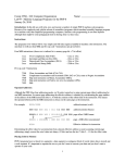
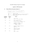
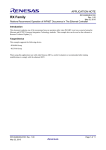
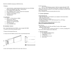
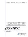
A PDP-8 Emulator
Brian J. Shelburne
Department of Mathematics and Computer Science
Wittenberg University
Springfield Ohio, 45501
e-mail: [email protected]
(937)-327-7862
Abstract: The clean, simple, and elegant architecture of the “classic” PDP-8 makes it a an ideal
candidate for studying concepts in computer organization. The PDP-8 Emulator is a program
running under MS-DOS that allows a user to write, edit, assemble, debug, trace and execute
PDP-8 machine code and assembler language programs and thereby obtain a “feel” for the
PDP-8. The program features a simple built-in text editor which is used to write and edit PDP-8
Assembler Language programs, an assembler to translate these programs into PDP-8 machine
code and a virtual PDP-8 engine upon which to execute the PDP-8 machine code. PDP-8
machine code can be executed from a “debugger” screen which allows the user to observe the
contents of registers and memory as the code executes or a program can be executed using an I/O
interface which requires the use of (user-written) PDP-8 I/O code. The paper discusses how to
use the PDP-8 Emulator and provides an introduction to PDP-8 architecture and PDP-8
Assembler Language since using the PDP-8 Emulator requires knowledge of both.
Categories and Subject Descriptors: C.0 Modeling of computer architectures, B.0 Hardware:
General: PDP-8, K.3 Computers and Education, K.2 History of Computing
Additional Keywords and Phrases: computer simulator
A PDP-8 Emulator Program
1. Introduction
The PDP-8 Emulator (pdp8main.exe) emulates PDP-8 architecture on an Intel 80x86 computer.
With it a user can edit and execute PDP-8 machine code or PDP-8 assembler language programs
and thereby develop a “feel” for the PDP-8. The design philosophy behind the PDP-8 Emulator
was to incorporate as much as possible the underlying architecture of an actual PDP-8. The intent
to make the virtual PDP-8 Emulator correspond closely to the architecture of a real PDP-8
accounts for some of the emulator’s “unusual” features. Much of the structure, terminology and
notation used in the emulator reflects that used in the original PDP-8.
The PDP-8 Emulator contains a number of “windows” into the virtual PDP-8. One window, the
“debug screen”, allows the user to observe the contents of all registers and memory. Using this
feature the user can enter PDP-8 machine code directly into memory and trace its execution.
Another feature is a small built-in text editor that allows the user to create and edit PDP-8
Assembler Language (PAL) programs. An assembler can be invoked to translate the PAL code
into machine code which can be executed by the virtual PDP-8. PDP-8 programs can be executed
using the debug feature or executed under the Run PDP-8 Screen feature which provides a simple
I/O interface. The latter requires writing PDP-8 I/O routines.
To use the PDP-8 Emulator, the user has to know something about the PDP-8 architecture. The
PDP-8 is a 12-bit word addressable machine with a single 12-bit accumulator and 4096 words of
1
memory (32 pages of 128 words each). Instructions are fixed length and are 12-bits “wide”.
Three bit op-codes permit only eight op-codes, although two of the eight op-codes (op-codes 6
and 7) use the other 9 bits for extended op-codes instead of for referencing memory. In particular
op-code 7 is a family of orthogonal “micro-instructions” which can be combined to generate a
surprisingly rich set of operations. There are four addressing modes: zero page addressing,
current page addressing, indirect, and auto-index indirect. The first two reflect the partition of
memory into 32 pages of 128 words each. The last one is used to handle data structures like
strings and arrays.
While later PDP-8 models supported features like hardware instructions to multiply and divide,
the emulator only supports the features found in the earliest PDP-8. For example it only supports
integer addition so multiplication and division must be done in software. This was to keep the
emulator design simple and easy to use. The PDP-8 is rather elegant in its ability to implement
complex operations using a limited instruction set.
As the real PDP-8 was programmed using PDP-8 Assembler Language (PAL), so too the
emulator can be programmed in PDP-8 Assembler. Since this is the primary way to write
programs for the emulator, much of the following paper is a quick tutorial in PDP-8 Assembler.
The Pascal source code for the emulator was compiled under Borland’s Turbo Pascal version 6.0
and will run in an MS-DOS Command Prompt window.
2
2.
An Overview of the PDP-8 Emulator
At the Main (opening) screen the user is presented with four options (plus Quit).
PDP-8 Emulation Program
Version 3.3 - Turbo 6.0
Fall 2001
Editor/Assembler
Help
Run PDP-8 Pgm
Quit
Use -> and <- to highlight choice. Use (Enter) to select.
Debug Screen : This allows the user to directly view the contents of memory and all
registers. The user can enter, execute and trace (single-step) simple PDP-8 programs.
Editor/Assembler : A simple text editor included as part of the emulator allows the user to
create, edit, debug, and assemble PPD-8 Assembler Language (pal) programs. A
successfully assembled program can be executed in the Debug Screen or through the Run
PDP-8 Program option
3
Help : On-line help is provided for the PDP-8 Assembler Language and for the PDP-8
Emulator.
Run PDP-8 Program : This provides a simple I/O interface for executing PDP-8
programs.
Options are selected by hitting a letter key (D, E, H, R, or Q) or using the arrow keys to highlight
the option and hitting (Enter). (Esc) can be used to return to the Main screen or from the Main
screen to quit the program.
The Debug Screen
Debug Screen 0000 0000 0000 0000 0000 0000 0000 L Accumulator
0000 0000 0000 0000 0000 0000 0000 0000 0 000000000000
0000 0000 0000 0000 0000 0000 0000 0000 0000 0000 0000 0000 0000 0000 0000 0000 L
ACC MQ
0000 0000 0000 0000 0000 0000 0000 0000 0 0000 0000
0000 0000 0000 0000 0000 0000 0000 0000 0000 0000 0000 0000 0000 0000 0000 0000 PC
IR
0000 0000 0000 0000 0000 0000 0000 0000 0200
0
0000 0000 0000 0000 0000 0000 0000 0000 0000 0000 0000 0000 0000 0000 0000 0000 CPMA
MB
0000 0000 0000 0000 0000 0000 0000 0000 0000 0000
0000 0000 0000 0000 0000 0000 0000 0000 0000 0000 0000 0000 0000 0000 0000 0000 SR
Run
0000 0000 0000 0000 0000 0000 0000 0000 0000
0
0000 0000 0000 0000 0000 0000 0000 0000 0000 0000 0000 0000 0000 0000 0000 0000 >
BkPt Dep Go Load MemPg PC Reset SwRg Quit UnAssmbl Write (Sp)SnglStep
CPU Registers are displayed on the upper right. The Link bit (used for a carry out from the
accumulator) and 12-bit Accumulator display are on the first row. Next come octal displays for
4
the same Link bit and same Accumulator and the Multiplier-Quotient register. Next are the
Program Counter register and Instruction Register (3 bits), then the Central Processor Memory
Address register and Memory Buffer register and finally the Switch Register and Run bit.
One 128-word page of memory is displayed in octal on the upper left (16 rows of 8 words with
row and column headers contains addresses). Use the PgUp and PgDn keys to display the
previous and next pages of memory. The highlighted position is the memory cursor which can be
moved using the arrow keys. Typing an octal number will insert that value at the memory cursor.
(The display above is page 1 of memory - words 200o (octal) through 377o. A suffixed ‘o’
denotes octal notation). The address of the memory cursor is always the value contained in
Program Counter.
The bottom is the command area where the user can enter single letter commands to Assemble a
line of code, set or clear a Break Point, Deposit a value to memory, Go (execute a program).
Load a program into memory (see Write option below), display a different Memory Page, enter
a value into the Program Counter (which also moves the memory cursor), Reset memory and
registers to zero, enter a value into the Switch Register, Quit the Debug Screen, Unassemble
the value at the memory cursor, Write the contents of memory to a file (which can be re-loaded see Load above), and single step (trace) through a program. On-line help provides more details
about these options.
5
The Editor/Assembler
Editor Edit Text Include File
Assemble Current Text
New Text
Read File
Save Text
Quit
The Editor/Assembler screen contains a number of features that allows the user to create, edit
debug and assemble text files of PDP-8 Assembler Language (pal) programs. Selecting Edit
Text will put the user in Edit mode (the cursor appears in the text area). The built-in editor is
simple and obvious to use. Use (Esc) or F10 to exit edit mode. The editor does not have a cut and
paste capability.
Assemble will assemble the current contents of the text window directly to memory (linkers and
loaders are not needed). A successful assemble will allow the user the option of creating a
standard list file which cross lists source code with object code. The assembled code in memory
can be executed from the Debug Screen or the run PDP-8 Program screen. A syntax error will
halt the assembly process putting the user in edit mode and placing the cursor at the line (not the
6
point in the line) where the error was found. This happens for each syntax error. (The process is
similar to the way Borland’s Turbo Pascal compilers found syntax errors.)
Edit Text puts the user in edit mode. Include File can be used to insert a text file at the cursor
position in the text area. New Text clears the text area and puts the user in edit mode. Read File
read contents of a text file into the text area after first clearing it. Save Text will save the
contents of the text area
The Run PDP-8 Screen
Run PDP-8 Screen L AC
MQ
PC
CPMA
MB
SR
0 0000 0000 0000 0000 0000 0000
Deposit AddrLoad Examine
Enter Value for Switch Register
Go
Clear
Punch
Reader
Quit
The Run PDP-8 Program screen provides an I/O interface in which to execute PDP-8 programs.
The upper portion functions as a 20 line display. Only a memory resident PDP-8 program can
generate output to this screen.
7
The contents (in octal) of seven registers are displayed. These are registers which would be
displayed on the console of a real PDP-8.
Of the nine selections, the first five (SwitchReg through Go) correspond to switches on the PDP8 console that allowed the user to enter values directly into the PDP-8. The sixth, Clear, clears
the screen display and sets all registers to 0. It leaves the contents of memory untouched. Punch
and Reader are used simulate I/O using a paper tape punch. (A standard PDP-8 terminal had a
paper tape punch attached to it). This advanced feature is only used if you want to simulate
reading or writing to paper tape.
SwitchReg: The PDP-8 Switch Register was a series of 12 toggle switches on the PDP-8 console
which could be set to any 12 bit number. When this option is selected the user is prompted for a
4 digit octal integer which is entered into the Switch Register and into the Memory Buffer (MB)
register.
Deposit: This deposits the contents of the Memory Buffer (MB) register to the memory address
given by the Central Processor Memory Address (CPMA) register. It then increments both the
Program Counter (PC) and CPMA registers.
AddrLoad: This deposits the contents of the Switch Register to the CPMA register and the
Program Counter (PC).
8
Examine: This fetches the contents of memory at the address contained in the CPMA register,
placing it in the MB register. It then increments the CPMA register. This is used to displace the
contents of memory from the the PDP-8 console.
The SwitchReg, Deposit, AddrLoad and Examine options were included to make the PDP-8
Emulator interface more realistic. On a physical PDP-8, an operator could use the SwitchReg,
AddrLoad and Deposit switches to enter a small program (like the code for a program loader)
directly into the memory of a PDP-8. Using SwitchReg, AddrLoad and Examine an operator
could examine the contents of memory. Both of these actions can be simulated on the PDP-8
Emulator.
Another action is to set the Program Counter to the entry point of a program. Once a program is
in memory, the Switch Register can be loaded with the address of entry point for the program, the
AddrLoad switch can be used to copy the contents of the Switch Register to the Program Counter
and the Go option (below) can be used to start execution.
Go : This begins execution of the program in memory starting with the instruction whose address
is given in the PC register. Execution continues until either a halt instruction is encountered or
the user hits Ctrl/C (abort).
Clear : This clears the screen and the contents of all registers. Memory is untouched.
9
3. A Quick Overview of PDP-8 Architecture
The following sections provide a quick introduction to the architecture of the PDP-8 and to
PDP-8 Assembler Language (PAL) programming. The sections are brief and do not cover all
details but knowledgeable readers should be able to learn enough to write and execute simple
programs for the PDP-8 Emulator.
The memory of the PDP-8 consists of 4096 (212) twelve-bit words. Memory is partitioned into 32
pages of 128 words each. A 12-bit address consists of a 5 bit pages number (bits 0 - 4) and a 7
bit offset (bits 5 - 11). For example address 0200o is page 01o offset 000o.
Within a word bits are numbered left to right 0 - 11 with bit 0 being the most significant bit.
msb ->
<- lsb
+---+---+---+---+---+---+---+---+---+---+---+---+
0
1
2
3
4
5
6
7
8
9
10 11
There is a single 12-bit accumulator (AC) with a one-bit link register (L) that “captures” any
carry out of the accumulator. Many PDP-8 instructions make implicit use of the link-accumulator
pair.
Link bit
Accumulator
+---+
+---+---+---+---+---+---+---+---+---+---+---+---+
0
1
2
3
4
5
6
7
8
9
10 11
10
An additional 12-bit multiply-quotient register (MQ) was used for multiply/divide operations in
advanced models of the PDP-8 but these operations are not supported by the PDP-8 Emulator
program.
Special purpose registers include a 12-bit Console Switch Register (SR) used to enter values
directly from the console of the PDP-8, a 12-bit Program Counter register (PC) which holds the
address of the next instruction to execute, a 3-bit Instruction Register (IR), a 12-bit Central
Processor Memory Address register (CPMA) and a 12-bit Memory Buffer (MB). The latter two
registers were used by the CPU to access memory with the former containing the address to be
read/written and the latter containing the value.
The PDP-8 has eight op-codes and three instruction formats. Op-codes 0 - 5 are memory
reference instructions (MRI) whose format is given below.
Memory Reference Instruction Format
+---+---+---+---+---+---+---+---+---+---+---+---+
| op-code |IA |MP |
Offset Address
|
+---+---+---+---+---+---+---+---+---+---+---+---+
0
1
2
3
4
5
6
7
8
9
10 11
Bits
Bit
Bit
Bits
0 - 2
3
4
5 -11
:
:
:
:
operation code
Indirect Addressing Bit (0:direct/1:indirect)
Memory Page (0:Zero Page/1:Current Page)
Offset Address
The MRI instruction format has room for only a 7 bit offset. To obtain a 12-bit address either five
zeros are prefixed to the offset (i.e. zero page addressing indicated by clearing bit 4 to 0) or the
five leading bits of the address of the instruction is prefixed to offset (i.e. current page addressing
indicated by setting bit 4 to 1). This means that any MRI instruction can directly access only 256
11
out of 4096 words. To access any other word in memory, indirect addressing is used (setting bit 3
equal to 1).
In the descriptions below. EAddr denotes “Effective Address” and C( ) denotes “contents of”. A
branch instruction is implemented by changing the contents of the PC register.
Memory Reference Instructions
Mnemonic
AND
TAD
ISZ
DCA
JMS
JMP
Op-code
0
1
2
3
4
5
Full Name : Description
bitwise and: C(AC) = C(AC) and C(EAddr)
twos complement add: C(AC) = C(AC) + C(EAddr); on carry out complement Link
increment and skip on zero: C(EAddr) = C(EAddr) + 1; if 0 then skip next instruction
deposit and clear accumulator: C(EAddr) = C(AC); C(AC) = 0
jump to subroutine : C(EAddr) = C(PC); C(PC) = C(EAddr) + 1
jump always: C(PC) = C(EAddr)
Note: A load instruction is performed by zeroing out the accumulator first (CLA: Clear Accumulator - see below)
followed by a TAD instruction. The Increment and Skip on Zero instruction (ISZ) followed by a Jump Always
instruction (JMP) is used to implement a counting loop by incrementing a negative count to zero. By itself ISZ can
also be used to increment a value in memory. DCA, Deposit and Clear Accumulator is a destructive store. The JMS
Jump to Subroutine instruction saves the return address at the first location in the subroutine and branches to the
second location. A return is accomplished by an in indirect Jump JMP.
Opcode 6 is an I/O operation or more exactly a family of I/O instructions. The op-code
instruction format (see below) contains two “operand” fields : a device number field in bits 3 - 8
(e.g. device 03 is a keyboard, device 04 is a printer) and an extended function field in bits 9 - 11
which specifies an operation for the device (e.g. function 001 is “skip if device flag set”). I/O on
the PDP-8 is a somewhat complicated and will be covered in detail in a later section.
12
Opcode 6 Instruction Format
+---+---+---+---+---+---+---+---+---+---+---+---+
| 1
1
0 |
device number
| function |
+---+---+---+---+---+---+---+---+---+---+---+---+
0
1
2
3
4
5
6
7
8
9
10 11
Bits 0 - 2 : op-code 6
Bits 3 - 8 : Device Number
Bits 9 - 11 : extended function (operation specification)
Like opcode 6, opcode 7 is a family of "micro-instructions" which include instructions to test,
increment, complement, and rotate the accumulator and/or link bit. Generally each bit in the
extended op-code field (bits 3 - 11) independently controls a different function. These functions
can be combined creating a class of fairly powerful instructions.
Op-code 7 instructions fall into three groups. The first group contains functions to clear,
complement, increments and/or rotate the link accumulator pair. The order of execution of
functions within a group are “prioritized” to prevent ambiguities (for example, a clear function
will occur before a complement function). Group two contains two sub-groups of conditional
skip functions. Group three functions reference the MQ register.
Op-code 7 Group One Microinstructions : bit 3 = 0
+---+---+---+---+---+---+---+---+---+---+---+---+
| 1 | 1 | 1 | 0 |cla|cll|cma|cml|rar|ral|0/1|iac|
+---+---+---+---+---+---+---+---+---+---+---+---+
0
1
2
3
4
5
6
7
8
9
10 11
13
Mnemonic
Op-code
Full Name : Description (priority number)
CLA
CLL
7200
7100
Clear Accumulator (1)
Clear Link (1)
CMA
CML
7040
7020
Complement Accumulator (2)
Complement Link (2)
IAC
7001
Increment Accumulator (3)
RAR
RTR
RAL
RTL
7010
7012
7004
7006
Rotate Accumulator and Link Right (4)
Rotate Accumulator and Link Right Twice (4)
Rotate Accumulator and Link Left (4)
Rotate Accumulator and Link Left Twice (4)
Note : Priority numbers 1 - 4 determine the order in which combined instructions are executed. Priority 1
instructions (e.g. CLA) are executed before priority 2 (e.g. CMA) etc. The combination CLA CMA would clear the
accumulator then complement it thereby setting all bits to 1. Some combinations occur so often that they have their
own mnemonics. For example CMA IAC : Complement Accumulator and Increment Accumulator (equivalent to
negating the accumulator) is given the mnemonic CIA (7041) : Complement and Increment Accumulator. STL : Set
Link to One is the mnemonic for CLL CML. GTK : Get Link (i.e. put the link in bit 11of the accumulator) is the
mnemonic for CLA RAL.
Op-code 7 Group Two Microinstructions : bit 3 = 1 and bit 11 = 0
+---+---+---+---+---+---+---+---+---+---+---+---+
| 1
1
1 | 1 cla sma sza snl 0/1 osr hlt 0 |
+---+---+---+---+---+---+---+---+---+---+---+---+
0
1
2
3
4
5
6
7
8
9
10 11
Mnemonic
Op-code
Full Name : Description (priority)
SMA
SZA
SNL
7500
7440
7420
Skip on Minus Accumulator (1)
Skip on Zero Accumulator (1)
Skip on Non-zero Link (1)
SPA
SNA
SZL
7510
7550
7430
Skip on Positive Accumulator (1)
Skip on Non-Zero Accumulator (1)
Skip on Zero Link (1)
SKP
7410
Skip Always (1)
CLA
OSR
HLT
7600
7504
7501
Clear Accumulator (2)
Or Switch Register with Accumulator (3): C(AC) = C(SW) or C(AC)
Halt (4)
Note : The three instructions SMA, SZA and SNL form one sub-group of conditional skip instructions; the three
instructions SPA, SNA and SZL form a second subgroup. Combinations of SMA, SZA and/or SNL will skip if at
least one condition is true. For example SMA SZA will skip if AC is less than or equal to 0. Combinations of SPA,
SNA, and/or SZL will skip if all conditions are true. For example SPA SNA will skip if AC is greater than 0.
Combinations between the two sub-groups are neither permitted nor necessary.
14
Like Group One, some Group Two combinations have their own mnemonics. LAS : Load Accumulator with Switch
Register is the mnemonic for CLA OSR
Op-code 7 Group Three Microinstructions : bit 3 = 1 and bit 11 = 1
+---+---+---+---+---+---+---+---+---+---+---+---+
| 1
1
1 | 1 cla mqa
mql
1 |
+---+---+---+---+---+---+---+---+---+---+---+---+
0
1
2
3
4
5
6
7
8
9
10 11
Mnemonic
Op-code
Full Name : Description (priority)
CLA
7601
Clear Accumulator (1)
MQA
MQL
7501
7420
Or Accumulator with MQ register (2) : C(AC) = C(AC) or C(MQ)
Load MQ register from Accumulator and Clear Accumulator (2): C(MQ) = C(AC);
C(AC) = 0
SWP
CAM
7521
7621
Swap AC and MQ registers (3)
Clear AC and MQ registers (3)
4.
PDP-8 Memory Reference Instruction Addressing Modes
Zero/Current Page Direct Addressing: Because the format of a PDP-8 memory reference
instructions (AND, TAD, ISZ, DCA JMS, JMP) only has “room” for a 7 bit operand, it’s
important to understand how effective addresses are obtained. An MRI instruction can only
reference an operand that is either on page zero or on the current page of memory, the current
page being the same one as the instruction itself. For current page addressing, this means that
most operands have to be fairly “close” to the MRI instruction that references them. Zero/Current
Page addressing mode is determined by bit 4 of the instruction.
Calculating Zero/Current Page Address Calculation (Optional). For zero page addressing (bit 4 =
0) five zeros are concatenated to the front of the seven bit operand to obtain a 12-bit address.
15
With current page addressing (bit 4 = 1) the leading five bits (page number) of the address of the
MRI instruction is used
Example (zero page): Address 6224o contains the instruction 1167o (written 6224/1167). Since bit 4 of the
instruction is zero, the effective address of this TAD instruction would be obtained by concatenating five zeros to
the seven-bit offset address
1
1
6
7
001 001 110 111 ->
op I M
offset
001|0|0|1 110 111
0
1
6
7
effective address -> 00000 + 1 110 111 = 000 001 110 111
for an effective address of 0167.
Example (current page) : On the other hand if we have 6224/1367, since bit 4 is one, the effective address of this
TAD instruction would be obtained by concatenating the leading five bits of the address of the instruction (110 01
from 6224) to the seven-bit offset address
6
2
2
4
1
1
6
7
110 010 010 100 <- address/contents -> 001 001 110 111
110 01 <- page number
1 110 111 <- offset
Effective address -> 110 01 1 110 111 = 6337
"Global" variables should be stored on page zero since page zero is accessible from any address
in memory. "Local" variables should be stored on the current page.
Indirect Addressing : Since zero/current page direct addressing can only address two pages
out of 32, to access the other 30 pages, the PDP-8 supports indirect addressing (bit three equals
1). Here the zero/current page address is the address of the effective address.
Auto Index Addressing : Memory locations 010 - 017 (on page zero) function as autoindex registers. That is, whenever these addresses are addressed using indirection, their contents
are FIRST incremented then used as the address of the effective address.
16
Example (auto-index addressing) : Suppose address 0010 contains the value 3407. Instruction 1410 obtains the
effective address as follows:
1
4
1
0
op I M offset
001 100 001 000 -> 001|1|0|0 01 000
Since indirection is used through address 0010, the contents at 0010 (3407) first incremented (3410) and this is the
effective address.
5. PDP-8 Assembler Language (PAL) Programs
The format of a PDP-8 Assemble Language instruction has up to five fields
symbolic address, opcode(s) i offset /comment
Commas terminate a symbolic address (label), a "/" indicates that comment follows and an "i"
denotes indirect addressing. All field are optional except for op-codes. For example, the
following code executes the operation c = a - b
Main, cla
tad
cia
tad
dca
hlt
jmp
cll
B
A
C
/
/
/
/
/
/
clear AC and Link
load B
negate it
add A : AC = A - B
store at C
halt
Main
The offset can be a number, a symbolic address, a dot ‘.’ (which is used to denote the current
address of the instruction) or a simple expression using the above. For example jmp .-5 could
be used in place of jmp Main. and if the address of B is one more than the address of A (see
the variable declarations below). tad A+1 could be used in place of tad B.
17
To allocate storage for variables and constants, use a symbolic address, (comma) followed by the
value (use 0 if you don’t care about the initial value).
A,
B,
C,
17
22
0
By default all values are octal. To specify a decimal use, suffix a d or use an 8 or 9 as a digit.
A,
B,
C,
17d
29
0
/ decimal 17
/ decimal 29 since 9 is not an octal digit
The assembler directive *nnnn where nnnn is any octal value is used to specify where code is to
be assembled in memory (the PDP-8 emulator generates non-relocatable code).
The directive $label indicates the end of the program and specifies label as the entry point
(address of the first instruction) for the program.
*200
Main, cla
tad
cia
tad
dca
hlt
jmp
*0300
A,
B,
C,
$Main
cll
B
A
C
/
/
/
/
/
/
clear AC and Link
load B
negate it
add A : AC = A - B
store at C
halt
Main
17d
29
0
/ decimal 17
/ decimal 29 since 9 is not an octal digit
In general symbolic addresses (identifiers and labels) must begin with a letter and contain only
letters and digits. Special characters and embedded blanks are not permitted. The assembler is
not case sensitive.
18
All numbers are considered octal unless they contain an 8 or 9 or have “suffix d”. A suffix “o”
(for octal) is also permitted but not necessary.
A number of characters have special meaning or uses
/ (slash)
denotes a comment
, (comma)
used to terminate a symbolic address but is not part of the symbolic
address itself
. (dot)
denotes the current address of the instruction
* (asterisk)
used to set the value of the location counter
$ (dollar sign)
denotes the end of the program
; (semi-colon)
terminates a statement; used for multi-statement lines
= (equal sign)
equates a symbol to a value (e.g. x=-1 sets the symbol x equal to -1) This
does not allocate storage.
‘ (single quote)
used to indicate a character (e.g ‘A’) or a string (‘Hello’). They should
occur in pairs
The code below uses a counting loop to sum the integers from 1 to N. It first initializes I to 0 then
within the loop increments it and adds it to Sum. The counting loop is controlled by the variable
Count which is initialized to minus N and incremented on each pass through the loop until it
equals 0. The ISZ instruction is used both for loop control and to increment I.
19
By convention most PAL programs begin on page one at location 0200.
/
/ Code Section
/
*0200
Main,
cla cll
tad N
cia
dca Count
dca I
dca Sum
Loop,
isz I
tad Sum
tad I
dca Sum
isz Count
jmp Loop
hlt
jmp Main
/
/ Data Section
/
*0300
/
N,
10
/
Count, 0
/
I,
0
/
Sum,
0
/
$Main
/
/
/
/
/
/
/
/
/
/
/
/
/
/
/
/
Code starts at address 0200
clear AC and Link
load N
negate it
deposit it to Count and clear AC
clear I (AC is zero)
clear Sum (AC is zero)
add 1 to I
load Sum (assumes AC is 0)
add in I
store result in Sum (AC cleared)
increment Count and skip on zero
otherwise loop
done
allows easy restart
Data starts at address 0300
N equals 8
Loop Counter
Added to Sum
Running Sum
end of pgm - entry point
To execute this program yourself, do the following:
1.
Start the PDP-8 Emulator and go to the Editor/Assembler screen. Hit Edit Text to go into
edit mode and enter the above code as is. When done use (Esc) or F10 to exit edit mode.
2.
Select Assemble to assemble the code. If there are errors, fix them and try again until you
get a “clean compile”. (At this point you may want to save your program to a file)
20
3.
Quit the Editor/Assembler and go to the Debug Screen. (Since this code does no I/O, you
can only see the results of the execution from the Debug Screen.). When you enter the
Debug Screen you should see page 1 of memory.
4.
Hit the Go command. If the program executes correctly you should see the result 44o
(36d) at address 0303. The memory cursor should be highlighting the 5200o instruction
(jmp Main) at address 215o.
5.
To single step through the program either use the arrow keys to reposition the memory
cursor to address 0200o or beginning single stepping with the jmp Main instruction where
the previous execution left off. As you hit the (Space) bar, observe how the accumulator
changes.
6. Calling Subroutines
The JMS - Jump to Subroutine (opcode 4) - instruction stores the return address at the first
address of the subroutine and branches control to the second location of the subroutine. A
return is made via an indirect jump.
Example : The following subroutine returns the absolute value of the accumulator
Abs, 0
sma
jmp .+2
cia
jmp i Abs
/
/
/
/
/
store return address here
skip on minus accumulator
otherwise jump to end and return
negate accumulator
return via indirect jump
21
Note : The dot ‘.’ is used to denote the current address of the instruction. The jmp .+2 will jump
to the second address after the current one
To call this subroutine use jms Abs. A complete program that computes the absolute value of
A - B using this subroutine is given below
/
/
Code Segment
/
*0200
Main, cla cll
tad B
cia
tad A
jms Abs
dca c
hlt
jmp Main
/
/
Subroutine
/
*0250
Abs, 0
sma
jmp .+2
cia
jmp i. Abs
/
/
Data Segment
/
*0300
A,
17
B,
22
C,
0
$Main
/
/
/
/
/
/
/
/
/
code starts at address 0200
clear AC and link
Load B
Negate B
A - B
take absolute value
store results at C
halt
to continue - goto entry point
/
/
/
/
/
/
subroutine starts at address 0250
store return address here
skip on minus accumulator
otherwise jump to end and return
negate accumulator
return via indirect jump
/ data starts at address 0300
/ entry point is Main
7. Doing Simple I/O
I/O on the PDP-8 can be done using programmed I/O transfers that make use of op-code 6
instructions. The format of an op-code 6 instruction had a 6-bit device number field and a 3-bit
function field. The PDP-8 Emulator only supports instructions to read from the keyboard (device
22
number 03) and write to the monitor/display (device number 04). The set of op-code 6 I/O
instructions implemented on the PDP-8 Emulator is given below
Op-code 6 Instruction Format
+---+---+---+---+---+---+---+---+---+---+---+---+
| 1
1
0 |
device number
| function |
+---+---+---+---+---+---+---+---+---+---+---+---+
0
1
2
3
4
5
6
7
8
9
10 11
Bits 0 - 2 : op-code 6
Bits 3 - 8 : Device Number
Bits 9 - 11 : extended function (operation specification)
Mnemonic
Op-code
Full Name : Description
KFC
KSF
KCC
KRS
KRB
6030
6031
6032
6034
6036
Clear Keyboard Flag:
Skip on Keyboard Flag Set
Clear Keyboard Flag and Accumulator
Read Keyboard buffer Static: AC4..AC11 = AC4..AC11 or Keyboard Buffer
Read Keyboard Buffer dynamic: C(AC) = 0; Keyboard Flag = 0;
AC4..AC11 = AC4..AC11 = AC4..AC11 or Keyboard Buffer
TFL
TSF
TCF
TPC
TLS
6040
6041
6042
6044
6046
Set Printer Flag
Skip on Printer Flag Set
Clear Printer Flag
Load Printer Buffer with Accumulator and Print: Printer Buffer = AC4..AC11
Load Printer Sequence: Printer Flag = 0; Printer Buffer = AC4..AC11
I/O is between bits 4 - 11 of the Accumulator (AC4..AC11) and an 8-bit I/O Device Buffer.
Device Flag
+---+
|0/1|
+---+
+—---+--------+
+--------+
|
|
| <==========> |
|
+----+--------+
+–-------+
AC4..AC11
I/O Buffer
8-bit ASCII characters are transferred between the right-most 8 bits of the accumulator (bits 4 11) and device buffer (keyboard or printer). Synchronization between the CPU and I/O device is
handled by a "device flag" bit. When the I/O device is “busy” the flag is cleared to 0; when the
device is ready, the flag is set to 1.
23
To perform I/O the CPU enters a “wait loop” (an example is given below). When the I/O device
is ready to send/receive a character, it sets the device flag to 1. The CPU detects that the device
flag is set (one of the op-code 6 functions is “skip on flag set”) which breaks it out of the wait
loop. Once out of the wait loop the CPU transfers the byte in the 8-bit device buffer to/from the
right most 8 bits of the accumulator and clears the device flag (another op-code 6 function is a
“transfer and clear flag”).
While ten op-code 6 I/O instructions are supported, only five are really needed : two for output to
the printer (TSF : Skip on Printer Flag Set and TLS : Load Printer Sequence) and three for input
from the keyboard (KSF : Skip on Keyboard Set, KCC : Clear Keyboard Flag and KRB : Read
Keyboard Buffer)
I/O is best done if the code is consolidated into subroutines. The following program demonstrates
the standard way to read and write characters. The program reads and echoes a character typed
from the keyboard ending when the user hits a carriage return (ASCII code 13). It uses two I/O
subroutines : GetChar and Type. GetChar reads a character from the keyboard returning it in the
accumulator. Type displays the 8-bit character in the accumulator to the output device (screen).
Both subroutine begin by entering a wait loop repeatedly check if the device flag is set (device is
ready). When the device flag is set, control breaks out of the loop allowing both to call a transfer
instruction to move the byte between the device buffer and the accumulator.
24
/
/ Code Segment
/
*0200
Main,
cla cll
kcc
tls
Again,
jms i GetChar
dca Hold
tad Hold
tad MCR
sna
jmp Done
cla cll
tad Hold
jms i Type
jmp Again
Done,
hlt
jmp Main
/
/ I/O routines
/
*0250
GetChar, 0
ksf
jmp .-1
krb
jmp i GetChar
Type,
0
tsk
jmp .-1
tls
cla cll
jmp i Type
/
/ Data Segment
/
*0300
Hold, 0
MCR,
-13d
$Main
/
/
/
/
/
/
/
/
/
/
/
/
/
/
/
/
/
/
/
/
/
/
/
/
clear AC and link
clear keyboard flag
wake-up printer
read a character
store it
get the character and
check if it’s a CR
if not skip next instruction
else done
clear AC
and load character
echo to screen
go again
return address here
is keyboard flag raised?
no - loop
yes - read character to AC
return
return address here
is printer flag raised?
no - loop
yes - print character
clear AC and link
return
/ minus ASCII code for CR
Notes: Use of the KCC instruction at address 0201 to initially clear the keyboard flag is standard.
The TLS instruction at address 0202 which actually causes the output device to display a null
characters (which is unprintable) seems also to be a standard way to initialize the output device.
Storing the negative value of the ASCII code you want to test for (in this case a minus 13
decimal) and then adding this value to check for equality is also standard approach. Finally,
GetChar only reads a character; to echo it to the screen you have to call Type.
25
Since this program does PDP-8 I/O, it can be executed from the Run PDP-8 Screen.
8.
A PDP-8 BIOS (Basic Input Output System)
Code to do basic I/O on the PDP-8 needs to be consolidated on a single page and made
accessible to any page in memory. Direct addressing restricts JMS calls to subroutine code on the
zero page or the current page. Placing subroutine code on every page where it is called causes
unnecessary duplication. Space limitations prevent using the zero page (which is accessible from
any page in memory) for the subroutine code. The trick is to use indirect subroutine calls using
the zero page to hold the entry points for the subroutines.
In the sample “hello world” program below we give the code for four basic I/O subroutines :
GetChar, Type, PrtStr (which prints a null terminated string of characters) and CRLF (which
prints a Carriage Return Line Feed combination, sort of like a newline character). While not
elaborate, these four routines suffice to allow the writing of PDP-8 programs which do I/O.
The code for all four subroutines is placed on page 30 of memory but the addresses of their entry
points are stored on page zero starting at address 0050. Since the zero page is accessible from any
page in memory, an indirect call (e.g. jms i PrtStr) is used to call the subroutine instead of a
direct call (e.g. not jms PrtStr).
26
/
/ Basic I/O Routine Vectors - Page 0
/
*0050
GetChar, XGetChar
Type,
XType
CRLF,
XCRLF
PtrStr,
XPrtStr
/
/ Code Segment - Page 1
/
*0200
Main, cla cll
/ clear AC and Link
kcc
/ clear keyboard flag
tls
/ wake up printer
cla cll
/
tad Str
jms i PrtStr
jms i CRLF
hlt
jmp Main
/
/ Data Segment
/
*0300
Str, .
/ Str stores its own address
‘Hello World!’ ; 0
/ Null Terminates String
27
/
/ Basic I/O Routines - Page 30
/
*7400
XGetChar, 0
/ store return address here
ksf
/ Is keyboard flag raised?
jmp .-1
/ no - loop
krb
/ yes - read character to AC
jmp i XGetChar / return
XType, 0
/ store return address here
tsf
/ is printer ready?
jmp .-1
/ no -loop
tls
/ yes - print character
cla cll
/ clear AC and Link
jmp i XType
/ return
XCRLF, 0
/ store return address here
cla cll
tad .+5
/ get CR
jms XType
/
and type it
tad .+4
/ get LF
jms XType
/
and type it
jmp i XCRLF
/ return
13d;10;
/ carriage return; line feed
XPrtStr,0
dca 10
/ store address at autoindex register 10
tad i 10
/ get character
sna
/ is it null?
jmp i XPrtStr
/ yes - return
jms XType
/ no - type it
jmp .-4
/ get next character
$Main
A note about how PrtScr works: PrtScr will display any null terminated string. The first word of
the string must contain its own address. The last word must be a null character. The declaration
*0300
Str, .
‘Hello World!’ ; 0
/ Str stores its own address
/ Null Terminates String
allocates 14 words of memory. Address 0300o contains 0300o (via the dot ‘.’ convention).
Addresses 0301o .. 0314o contain the ASCII characters of the string. Address 0315o contains 0.
The code for PrtStr assumes that the address of the string to be printed is in the accumulator
(which is why the code sequence cla cll; tad Str precedes the jms i PrtStr
instruction). PrtStr immediately deposits the address in the accumulator to memory address 10
28
which is one of the auto-indirect registers. It then uses auto indirect addressing to load each
character in the string checking that it’s not null before calling the Type command to display it.
9. PDP-8 Machine Code
Given the simplicity of PDP-8 architecture the machine code programming is possible (although
tedious since effective address calculation must be done by hand). Numeric code can be entered
directly into the PDP-8 memory from the Debug Screen. Simply position the memory cursor on
where you want to enter the code, type the octal value and hit enter. The value will be deposited
to that location and the memory cursor will advance to the next.
In the example below, we introduce the convention "nnnn/mmmm" which means address "nnnn"
contains contents "mmmm" (address/contents).
Example : The following program computes the absolute difference of A - B (i.e. |A - B|) storing
the value at C. A, B, and C are stored at addresses 0300 - 0302 respectively. nnnn/mmmm
denotes stored mmmm at address nnnn (0200/7300 denotes the value 7300 stored at address
0200). Before running be sure to set the PC equal to 0200.
0200/7300
0201/1300
0202/7041
0203/1301
0204/7500
0205/5207
0206/7041
0207/3302
0210/7402
clear accumulator and link
load B (from address 0300)
negate (complement and add 1)
add A (from address 0301
skip if negative
jump to address 0207
negate A - B to make positive
deposit |A - B| to C (address 0302)
halt
29
0300/0017
0301/0022
0302/0000
A
B
C
To execute the above program, do the following
1.
Go to the Debug Screen. Use the PC command (p0200) to position the memory cursor at
address 0200o and display page 1 of memory.
2.
Beginning at address 0200o enter the code as given above (7300 1300 7041 etc). After
entering each four digit octal number, hit (Enter) to advance the memory cursor to the
next location. After entering the last instruction 7402 at address 0210o, position the
memory cursor at address 0300o and enter the data (0017 0022).
3.
Reposition the memory cursor at address 0200o, the starting address for the code. Hit g
(Go) to execute the program or (space) to single step through the code. The answer will
eventually be stored at location 0302o
10.
Additional Documentation : The PDP-8 Emulator User's Manual
A number of features supported by the PDP-8 Emulator were not discussed. For example, the
PDP-8 supported interrupts which can be simulated on the PDP-8 Emulator. A teletype device
attached to PDP-8 had a paper tape reader. I/O with this device can simulated by the PDP-8
Emulator (recall the Punch Reader options on the Run PDP-8 Screen).
30
Additional information about the PDP-8 Emulator and PDP-8 Assembler Language can be
obtained from The PDP-8 Emulator User’s Manual, written by the author. The manual is used as
a supplementary text book for a course in computer organization and it contains a fairly complete
introduction to PDP-8 Assembler Language programming along with a number of sample PDP-8
Assembler language programs. It also contains a fuller description of the features and capabilities
for the PDP-8 Emulator.
The following is a list of chapters included in the manual
Chapter 1
An Overview of PDP-8 Architecture and the PDP-8 Emulator Program
Chapter 2
PDP-8 Addressing Modes
Chapter 3
PDP-8 Machine Language
Chapter 4
The PDP-8 Assembler Language
Chapter 5
The PDP-8 Instruction Set
Chapter 6
Subroutines, I/O, and Running PDP-8 Programs
Chapter 7
Advanced Programming Examples
Appendix A: PDP-8 Instructions
Appendix B: PDP-8 Addressing Modes
Appendix C: PDP-8 Emulator Commands
Appendix D: Binary and Octal Integers
31