1
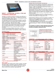
LOKUS K - Standalone controller Voltage drops and cable signal interferences When you connect the controller, use cable with a diameter of at least 0.22mm2. If the cable length exceeds 25m, use one twisted pair of UTP cables for the positive (+) pole and one for the negative (-) pole. The cable length between the power supply and controller should not exceed 50m. LOKUS K – STANDALONE CONTROLLER The Lokus is a controller with built-in proximity card reader and keypad. It is designed for residential and business buildings, shops, etc. In various operation modes, the controller allows access for up to 69 users (1 master card & code and 69 user cards or codes). The entire set-up procedure is carried out with master card or master code. User cards and codes can either be registered or deleted. The controller signals normal operation with flashing red and green LED. It can also be used as a Wiegand 26-bit reader. TECHNICAL DATA LOKUS K Reading frequency Reading distance Current consumption Operating voltage Operating temperature Protection Memory Inputs Outputs Cabel Dimensions (mm) Keypad 125kHz Up to 12cm 60mA From 9V to 14V DC From -20°C to 70°C IP65 69 cards or codes Door status Push button Transistor output for el. strike 0.5A Flat cable 20cm 58x120x17 (WxHxD) Numeric, illuminated, with gold plated contacts 3 – gray El. strike output / Data 0 4 – gray Not connected/ Data 1 Door status switch input/ Buzzer input Push button input / LED input 6 – gray LED DIODES Color Flashing red/green Lit green Lit red Reading distance depends on where the controller is installed. The presence of metal or interferences can significantly reduce reading distance. It is not recommended to install controllers closer than 30cm from each other in any direction. Otherwise, it may result in inaccurate readings or, indeed, in the controller not reading at all. Installation of Lokus K CONNECTION CABLE Description/Wiegand Wire-Color 26-bit 1 – red 9-14V DC 2 – gray GND 5 – gray Take into consideration that a 0.22mm2 cable has a resistance of approximately 9 ohm per 100m. The power supply at the end of cable, should be a minimum of 9V. If you are using el. strike, it is highly recommended that the voltage drop is calculated. At greater distances, a thicker cable of 0.5mm2 or more should be used wherever possible. If the load is, for example, 0.5A (with el. strike) then, on the 0.22mm2 cable voltage drop will be 4.5V at 100m. For the device with 60mA consumption, the voltage drop is 0.5V. Specification Power supply Ground Max. 0,5A Active = GND Active = GND Active = GND Active = GND Description Normal mode El. strike is unlocked Card or code has no rights Power supply The controller needs external power supply to operate. The Spider W40 power supply is sufficient to power two controllers and two 12V electric strikes or two 12V magnetic locks (0.5A). If you use the controller and low consumption electric strike (0.25A) you can use power supply Spider W5. Remove black plastic screw covers on the top and the bottom of the controller. Install the controller to the wall with two supplied screws. Use diagonal holes - it enables a small correction of the position of the controller (up, down, left, right). When the controller is installed, put the screw covers back on. Inputs, outputs and environment Inputs: Inputs are realized with opto-isolators. The input is active, when pulled to Ground with an open collector transistor or mechanical switch, which is connecting the input pin of the controller to the Ground. Outputs: Output has a pre-installed protection diode for inductive load. It is also protected from current overload. The best way is to use a 0.25A el. strike or a 0.5A el. magnet, which has to be connected to the same positive pole (+) as the controller. Connect the negative pole (-) to the door strike output (wire 3). When the output is active it is pulled to ground. This can be changed with function 5 – negate output (for el. magnet). Environment: The controller has IP65 protection, but you must assure good cable joints, protected against moisture, otherwise corrosion may damage the controller. Damage in such cases is not covered by the warranty. Lokus K-1 reading range: The controller has a program algorithm that, at power start, sets parameters based on the installation environment, so as to ensure an optimal reading range. DO NOT install the controller directly on metal surfaces and/or cover it with a metal cover; it may stop working/reading. If you plan to test the controller and move it onto different surfaces, then you have to reset it (power off/on) on each surface. 5/2014 Black line www.codeks.eu LOKUS K - Standalone controller PROGRAMMING The entire set-up procedure is carried out with the master card or code. The master card and code cannot be replaced or duplicated. After registration the master card and code should always be kept in a secure place. You cannot change any setting without them and neither can we. Keep that in mind when storing the master card and code. Programming Lokus with the master card First connection to the power supply and registration of the master card: Turn the power supply on (2 beeps indicate power on) and approach a card you wish to be the master card (3 beeps indicate a successful registration). The first card registered becomes the master card. All the other cards will be registered as users (user cards). Usage of master card: If you hold the master card in front of the controller, every two seconds a double beep is heard. The number of double beeps indicates the programming function. PROGRAMMING FUNCTIONS WITH MASTER CARD Function Description 1 Register or delete user cards 2 Pulse time/ Duration of active output or toggle mode 3 Door status switch input/ time till pre-alarm 4 Pre-alarm and alarm/ duration of pre-alarm 5 Negate output 6 Delete a lost card 7 Delete a lost card 9 Switch to Wiegand 26-bit 13 Delete all Function 1) User cards Register or delete user cards. Setup: Approach the master card and remove it after 1 double beep. Within a period of three seconds approach a user card. The user card is now registered and with it, you can open output on the controller. If the card has already been registered, it is now deleted and its position is now empty. Next registered card will take the first available position on the list or position of the deleted card. To delete a lost user card, you must maintain a list of registered cards and codes, arranged in order of registrations (positions). Function 2) Pulse time/ Duration of active output or toggle mode Set the duration of active output/ the time in which you can open door or set output to toggle mode. Toggle mode means, if the user card is registered, output will remain opened (if it was closed) or closed (if it was open) till next registration. Set the duration of active output: Approach the master card and remove it after 2 double beeps. The controller will start to beep every second. Each beep indicates 1 second of active output. Duration of active output can be max. 10 seconds. When you hear the required number of beeps, approach a user card for confirmation. Set toggle mode: Approach the master card and remove it after 2 double beeps. Approach a user card before the first beep. Toggle mode is selected. Function 3) Door status switch input Set the time till pre-alarm / time in which the door can stay open, without triggering the pre-alarm and consequently the alarm. This function is used when the door status switch on el. strike is connected to Input0/I0/wire 5 on the controller. Setup: Approach the master card and remove it after 3 double beeps. The controller will start to beep every second. Each beep indicates 1 second till pre-alarm. Duration of the time till prealarm can be max. 10 seconds. When you hear the required number of beeps, approach a user card for confirmation. Function 4) Pre-alarm and alarm/ duration of pre-alarm Set the pre-alarm time. This is the time in which the controller, with short beeps, alerts you that the door was left open. If you don’t close the door in the pre-alarm time, the alarm will be triggered and signaled with long beeps by the controller. Setup: Approach the master card and remove it after 4 double beeps. The controller will start to beep every second. Each beep indicates 1 second of the pre-alarm time. Duration of the prealarm time can be max. 10 seconds. When you hear the required number of beeps, approach a user card for confirmation. Function 5) Negate / switch output state This function is used, when you connect an electric strike or electric magnet which needs power supply to remain in locked state. Setup: Approach the master card and remove it after 5 double beeps. Within a period of three seconds approach a user card for confirmation. The output state will be switched from the current one. Function 6) Delete a lost card Delete the next card on the list. Use this function if you lost a card and you wish to delete it from the controller. In order to use this function you must maintain a list of registered cards and codes, arranged by order of registrations so that you can find the card or code, which was registered before the lost one. Setup: Approach the master card and remove it after 6 double beeps. Within a period of three seconds approach the user card, which was registered before the lost one. This will delete the lost user card. Next registered card or code will take the position of a deleted card. Function 7) Delete a lost card Delete the previous card on the list. Use this function if you lost a card and you wish to delete it from the controller. In order to use this function you must maintain a list of registered cards and codes so that you can find the card or code, which was registered after the lost one. Setup: Approach the master card and remove it after 7 double beeps. Within a period of three seconds approach the user card, which was registered after the lost one. This will delete the lost user card. Next registered card or code will take the position of a deleted card. Function 9) Switch to Wiegand 26-bit Switch between the controller and Wiegand 26-bit reader. When you switch the controller on, it beeps twice in the controller mode and once in the Wiegand 26-bit mode. Switch to Wiegand 26-bit: Approach the master card and remove it after 9 double beeps. The controller will start to beep every second. Each beep presents different function, which is selected with a user card. 1. beep – If you approach a user card after 1 beep, the controller will switch to Wiegand 26-bit reader and will delete everything. 2. beep – If you approach a user card after 2 beeps, all data will be deleted. The controller will be reset to default. 5/2014 Black line www.codeks.eu LOKUS K - Standalone controller Switch from Wiegand 26-bit to controller: Right after turning the power supply on, when the controller has both LEDs lit, approach a user card and remove it after 9 beeps. Function 13) Delete all Reset/delete all data to default. Setup: Approach the master card and remove it after 13 double beeps. Within a period of three seconds approach a user card. This will delete all data and reset the controller to default settings. The controller will confirm this with a long beep, followed by a double beep. Programming Lokus with the master code The default master code is 1234. The maximum code length is 6 digits. The master code must be CHANGED for security reasons, because the default one is written in controller’s manual and with it, anybody can set himself his own code, to open YOUR door. Function 4) Pre-alarm and alarm Set the pre-alarm time. This is the time in which the controller, with short beeps, alerts you that door was left open. If you don’t close the door in the pre-alarm time, the alarm will be triggered and signaled with long beeps by the controller. Setup: Enter the master code and press . Press 4 and . Enter the duration of pre-alarm time in seconds (max. 10 seconds) and press . Function 5) Negate / switch output state This function is used when you connect an electric strike or electric magnet which needs power supply to remain in locked state. Turn on the negated output: Enter the master code and press . Press 5 and . For confirmation press 1 and . The output state will be switched from the current one. PROGRAMMING FUNCTIONS WITH MASTER CODE Function Description 0 Change master code 1 Register or delete user codes 2 Pulse time/ Duration of active output or toggle mode 3 Door status switch input/ time till pre-alarm 4 Pre-alarm and alarm/ duration of pre-alarm 5 Negate output 9 Switch to Wiegand 26-bit 13 Delete all Function 9) Wiegand 26-bit Switch between the controller and Wiegand 26-bit reader. When you switch the controller on, it beeps twice in the controller mode and once in the Wiegand 26-bit mode. Switch to Wiegand 26-bit: Enter the master code and press . Press 9 and . Press: 1 and – The controller will switch to Wiegand 26-bit reader and will delete everything. 2 and – The controller will delete all data and reset to default. Switch from Wiegand 26-bit to controller: Right after turning the power supply on, when the controller has both LEDs lit, approach a user card and remove it after 9 beeps Function 0) Master code Change the master code. Setup: Enter the default master code and press . Press 0 and . Enter the new master code and press . Again enter the new master code and press . Store the master code in a secure place. Function 13) Delete all Reset/ delete all data to default: Enter the master code and press . Press 13 and . For confirmation press 1 and . This will delete all data and reset the controller to default settings. The controller will confirm this with a long beep, followed by a double beep. Function 1) User codes Register or delete user codes. Setup: Enter the master code and press . Press 1 and . Enter the new user code and press .Again e nter the new user code and press . User code is now registered and with it, you can open output on the controller. If the code has already been registered, it is now deleted. Next code or card you register, will take the first empty position in the system. Default settings: A three-second pulse, five-second open time, four-second prealarm time, door switch and push button have NO contact; output is set for fail secure el. strike. The controller is in standalone mode. Default master code is 1234. Function 2) Pulse time/ Duration of active output or toggle mode Set the duration of active output/ the time in which you can open door or set output to toggle mode. Toggle mode means, if the user card is registered, output will remain opened (if it was closed) or closed (if it was open) till next registration. Set the duration of active output: Enter the master code and press . Press 2 and . Enter the duration of active output in seconds (max. 10 seconds) and press . Set toggle mode: Enter the master code and press . Press 2 and . Press 0 and . Function 3) Door status switch input Set the time till the pre-alarm / time for which door can stay open, without triggering the pre-alarm and consequently the alarm. This function is used when the door status switch on el. strike is connected to Input0/I0/wire 5 on the controller: Setup: Enter the master code and press . Press 3 and . Enter the duration of time till pre-alarm in seconds (max. 10 seconds) and press . ORDERING CODES LOKUS [box]-[card] Box: K Card: 1 – reading frequency 125kHz (cards) Code Specification LOKUS K-1 Standalone controller in K box, Frequency 125kHz OTHER Warranty only applies when the Lokus controller is powered with the power supply form the Spider family. Please read through our warranty and disclaimer statements. Connection scheme and additional support for the use of this product can be found on: http://www.jantar.si/forum/en CONTACT: Jantar d.o.o. Kranjska cesta 24 4202 Naklo SLOVENIA web: www.codeks.eu mail: [email protected] 5/2014 Black line www.codeks.eu