1
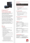
ISC910-1-0-GB-XX ISC921-5-0-GB-XX The ImproX IXP20 is a fully featured, stand-alone Access Control System supporting up to 1 000 Tagholders and 5 000 transactions. Designed for ease of use, the IXP20 System allows for the realtime monitoring and controlling of residential, as well as small or medium commercial and industrial sites. The IXP20 Controller, built on either an ImproX iTT or iTRT Door Controller platform, allows connection of 2 Readers direct to the Controller. The System is easily expanded to up to 8 Doors, all in Antipassback (APB) Mode. The IXP20 System offers an easy upgrade path with a simple firmware change enabling it to be included in a larger IXP System. Housed in an ABS Plastic cabinet, the IXP20 Controller is available in 4 models to best suit your individual needs: Models ISC910 and ISC920 offer a costeffective Ethernet connection and an easy-touse Web Interface. These models only need an internet browser to interact with the Controller and offer the added ability to backup your Database to PC. IXP20 Net also provides access to various Web-based Reports. Models ISC911 and ISC921 do not need a PC connection. Boasting a two-and a half-inch Graphics Touch Screen, these models allow complete System configuration at the Controller in addition to the standard Web UI. A Screen Lock and Password option ensure your settings remain secure. The IXP20 Touch also provides access to various Controller-based Reports. Support for up to 3 Tags per Tagholder. 2 Reader Fixed Addresses reserved for the Controller. Support for up to 16 Reader Fixed Addresses (allowing for connection of up to 8 Terminals). An RS485 Terminal Communications Bus allowing connection to the ImproX (iTT) Intelligent Twin Antenna Terminal and the ImproX (iTRT) Intelligent Twin Reader Terminal. Uses AES 128-bit Encryption through a Diffie Hellman key exchange to ensure secure communications. A TCP/IP Bus which links the System Controller to the Host PC. End of Line (EOL) Sensing on Door Open Sensor (DOS) Inputs. An excellent user interface consisting of 14 LED “Diagnostic Indicators”. Two independent single-pole, double-throw (SPDT) Relay Outputs that allow you to interface to door strikes, magnetic locks and other third-party devices (for example alarm panels or lighting). Four Digital Inputs including two Door Open Sensor (DOS) and two Request to Exit (RTE) Inputs. Added ability to interface with Motor and Solenoid Locks. Connects to the PC using a standard Ethernet cable. A Firmware Upgrade Utility (downloadable from Web) to upgrade Firmware while installed on-site, without removal of the Controller. 3-Year Warranty on Hardware. Support for up to 18 Holidays. Daylight Savings Support. Support for up to 8 Tagholder Access Groups. Allows for Batch Loading of Tags. User configurable Tag loading Template. When used with a Keypad Reader System support includes: Reason Codes Personal Access Codes (PAC) PIN-codes Stores all information locally on the Controller. Allows you to save the entire Database to the PC for backup and restore purposes. Offers the following Reports: Access Report Status Report Audit Report Hours Worked Report Supports 1 Anti-passback (APB) Zone. The IXP20 Web UI allows export of CSV data from the Web browser. The IXP20 Web UI works with both Windows® Internet Explorer 8 (and above) or alternatively Firefox 3 (and above). The IXP20 Touch allows you to carry out registration of 125 kHz and 13.56 MHz Tags using the Controller’s internal Reader. IXP20 Touch Controllers also include the Web UI. Interfaces with the full range of ImproX 125 kHz Antenna Readers. Antenna Reader read capability using the following Tags: Slim Tags, Omega Tags, Philips HITAG™ 1, Philips HITAG™ 2 and HID 125 kHz Tags. NOTE: Operates at 10 to 30 V DC. System support for up to 8 Doors on the RS485 Terminal Bus. Supports up to 1 000 Tagholders. ISC920-0-0-GB-XX XXX9XX-X-X-GB-XX Buffers up to 5 000 Transactions. CAUTION: ISC911-5-0-GB-XX The IXP20 System does not support the use of HID 1346 Proxkey II Tags. HID is a registered trademark of HID Global Corporation (an ASSA ABLOY Group Brand). 16-step Auto-tune allows for cable distances of up to 25 m (82 ft) for Non-keypad Antenna Readers and up to 16 m (53 ft) for Keypad Antenna Readers. Connection to up to two Antenna Readers per Controller, allowing Relaxed or Full Anti-passback (APB) access. Interfaces to the following ImproX Readers: ImproX Multi-discipline Readers. ImproX Wiegand Reader. Power Requirements (ISC910) Current (mA) Power (W) : 90 1.08 Offers full Wiegand Support. Interfaces with the ImproX RF Receiver. Input Voltage 12 V DC with no Antennas attached Peripheral read capability using the following Tags: Slim Tags, Omega Tags, Mifare® Standard, Mifare® Ultralite, FeliCa, Desfire, HID iClass, Philips HITAG™ 1 and Philips HITAG™ 2. Input Voltage 24 V DC with no Antennas attached : 50 1.20 Input Voltage 12 V DC with Antennas attached : 100 1.20 Input Voltage 24 V DC with Antennas attached : 60 1.44 CAUTION: NOTE: The IXP20 System does not support the use of HID 1346 Proxkey II Tags. HID, FeliCa and MIFARE® are registered trademarks of HID Global Corporation (an ASSA ABLOY Group Brand), The Sony Corporation and Koninklijke Phillips Electronics N.V. respectively. Power Requirements (ISC911) Connection to up to two Readers or Third-party Devices per Controller, allowing Relaxed or Full Anti-passback (APB) access. The following Tag read ranges apply to the ISC911 and ISC921 models’ internal registration reader only: Current (mA) Power (W) Input Voltage 12 V DC with no Antennas attached : 140 1.68 Input Voltage 24 V DC with no Antennas attached : 65 1.56 Input Voltage 12 V DC with Antennas attached : 150 1.8 Input Voltage 24 V DC with Antennas attached : 75 1.8 Relay Power Requirements : An additional ~0.4 W per Relay in use. Permissible Input Supply Ripple Voltage (Max) : 1 V PP at 50 Hz. Power Input Protection : Reverse polarity, over-voltage and over-current protection are provided on the Terminal. Real Time Clock Backup Battery (RTC) Length : 128 mm (5 in). Width : 166 mm (7 in). Height : 55 mm (2 in). ISC910 : 302 g (11 oz). ISC911 : 367 g (13 oz). ISC920 : 314 g (11 oz). ISC921 : 368 g (13 oz). Cabinet Material : ABS Plastic. Colour : Black. Approximate Weight Operating Temperature : -25oC to +60oC (-13oF to +140oF). Battery Type : 1 x 3 V, CR2032, Lithium cell battery. Battery Life : 2 Years with power OFF, 5 years with power ON, 5 years storage with Battery Tab in place. Connection : Standard Ethernet RJ45 connector. 10/100 Base T, half or full duplex. Protocol : ImproX Proprietary Protocol. Electrical Interface : RS485. Baud Rate : 38 400. Data Format : 8 data bits, no parity, 1 stop bit. Communications Protocol : ImproX Secure Communications Protocol. Line Termination (RS485) : Provision is made for line termination. Unit Status : Slave. Antenna Port : 2 Fully functional Antenna Reader Ports. Storage Temperature : -40oC to +80oC (-40oF to +176oF). Humidity Range : 0 to 95% relative humidity at +40oC (+104oF) non-condensing. CE Approval : EN301 489-3 and EN301 489-1. FCC Approval : Pending. Dust & Splash Resistance : Designed to work in an indoor (dry) environment similar to IP40. The Controller is not sealed against water. Input Type : 4 Dry-contact Digital Inputs. 1 m (3.28 ft) drop (in packaging). Detection Resistance Range : < 2 kOhm. Protection Range : +15 V continuous. Input Type : 2 Dry-contact inputs. Protection Range : +15 V continuous. Approvals Drop Endurance : Door Lock Input Voltage : 10 V DC to 30 V DC, polarity sensitive. Page 2 Relay Output : 2 Independent, single-pole, doublethrow (SPDT) Relays, each with NO, COM and NC contacts. Reader 1 Wiegand and Reader 2 Wiegand allow connection to the ImproX Multi-discipline Readers and Wiegand Readers. The function is selectable via the DIP-switches. Contact Ratings : 10 A at 28 V DC, 5 A at 220 V AC, 12 A at 120 V AC. Power Output : 12 V DC and 5 V DC (selectable) at maximum 200 mA. Modes Supported : Tag + PIN-code or Reason Code. Operations : 100 000 Minimum. Baud Rate : 9 600. Data Format : 8 data bits, no parity, 1 stop bit. Electrical Interface : TTL Full Duplex. Communications Protocol : ImproX Proprietary Protocol. Input Type : 4 Dry-contact inputs. Detection Resistance Range : < 2 kOhm. Protection Range : +15 V continuous. Input Type : 2 Dry-contact inputs. Protection Range : +15 V continuous. Relay Output : 2 Relays, Form C, each with NO, COM and NC contacts. Contact Ratings : 10 A at 28 V DC, 5 A at 220 V AC, 10 A at 120 V AC. Operations : 100 000 Minimum. Anti-tamper Switch : 1 Internal Switch. Reader Frequency : 125 kHz and 13.56 MHz. Reader Read Capability : Slim Tags, Omega Tags, Mifare® Standard, Mifare® Ultralite, FeliCa, Desfire, HID iClass, Philips HITAG™ 1 and Philips HITAG™ 2. Anti-tamper Switch : 1 Internal Switch. Reader Frequency : 125 kHz. Reader Read Capability : Slim Tags Omega Tags, Philips HITAG™ 1, Philips HITAG™ 2 and HID 125 kHz Tags. CAUTION: The IXP20 System does not support the use of HID 1346 Proxkey II Tags. General Door Lock Input Voltage : 10 V DC to 30 V DC, polarity sensitive. Power Requirements (ISC920) 12 V DC with no peripherals connected and relays off : 24 V DC with no peripherals connected and relays off : Current (mA) Power (W) 75 0.90 40 0.96 Power Requirements (ISC921) Current (mA) Power (W) 130 1.56 12 V DC with no peripherals connected and relays off : 24 V DC with no peripherals connected and relays off : Relay Power Requirements : An additional ~0.4 W per Relay in use. Permissible Input Supply Ripple Voltage (Max) : 1 V PP at 50 Hz. Power Input Protection : Reverse polarity, over-voltage and over-current protection are provided on the Terminal. 60 1.44 CAUTION: NOTE: Real Time Clock Backup Battery (RTC) Battery Type : 1 x 3 V, CR2032, Lithium cell battery. Battery Life : 2 Years with power OFF, 5 years with power ON, 5 years storage with Battery Tab in place. Connection : Standard Ethernet RJ45 connector. 10/100 Base T, half or full duplex. Protocol : ImproX Proprietary Protocol. Electrical Interface : RS485. Baud Rate : 38 400. Data Format : 8 data bits, no parity, 1 stop bit. Communications Protocol : ImproX Secure Communications Protocol. Line Termination : Provision is made for line termination. The IXP20 System does not support the use of HID 1346 Proxkey II Tags. Because of the way standard Wiegand Readers handle HID Tag codes, IXP20 Sites using standard Wiegand Readers can only support one of two options: HID Tags only or other 125 kHz Tag types (such as Slim Tags, Omega Tags, Philips HITAG™1 and Philips HITAG™ 2 depending on the Reader). For HID Tags only, set the DIP-switch to Wiegand Open Format and the Wiegand Reader to HID Raw Mode. For any other Tag type, set the DIPswitch to Wiegand 26-bit/44-bit. For more information refer to the Installation Manual for the IXP20 Controller (iTRT Platform). If you need a combination of HID Tags and other Tag types, make use of the ImproX Multi-discipline Readers. Type : Thin Film Transistor Liquid Crystal Display (TFT-LCD). Resolution : 240 x 320 Pixels. Colour : 65 K Colour Screen. Back-lighting : Permanently on. Volume and Tone : Single tone, with a 3-step adjustable volume. Page 3 Status Indicator Status LED : Continuous Red. Upgrade Mode : Flashing Red (Steady). RS485 Communications Failure : Flashing Red (Intermittent). Relay [2] : Continuous Red on activation of the Relay. Relay [1] : Continuous Red on activation of the Relay. Reader 2, RTE [2] : Continuous Green on detected contact closure. Reader 2, DOS [1] : Continuous Green on detected contact closure. Reader 1, RTE [2] : Continuous Green on detected contact closure. Reader 1, DOS [1] : Continuous Green on detected contact closure. RS485 RX : Flashing Green as per incoming data. RS485 TX : Flashing Red as per outgoing data. Locked : Continuous Green when locked. Unlocked : Continuous Green when unlocked. Enet Act (Ethernet Activity) : Flashing Red LED. Enet Spd (Ethernet Speed) : Continuous Red for 100 Mbps (Default). Off for 10 Mbps. Enet Lnk (Ethernet Link) : Continuous Red on connection to network. Diagnostic Indicators For extra information relating to this product refer to the: IXP20 Controller (ImproX iTT Platform) Hardware Installation Manual (ISC304-0-0-GB-XX). IXP20 Controller (ImproX iTRT Platform) Hardware Installation Manual (ISC304-0-0-GB-XX). IXP20 Touch User Manual (ISC305-0-0-GB-XX). IXP20 Net User Manual (ISC306-0-0-GB-XX). Order the IXP20 Controller using the following Part Numbers: ISC910-1-0-GB-XX: ImproX IXP20 Twin Antenna Controller with Web Interface. ISC911-5-0-GB-XX: ImproX IXP20 Twin Antenna Controller with Touch Screen. ISC920-0-0-GB-XX: ImproX IXP20 Twin Reader Controller with Web Interface. ISC921-5-0-GB-XX: ImproX IXP20 Twin Reader Controller with Touch Screen. CAUTION: We reserve the right to nullify the products warranty where you have not properly installed the Metal-oxide Varistors. This product conforms to our Warranty details on www.impro.net. Page 4 Figure 1: IXP20 System Overview Page 5 This Product Specification Catalogue applies to the ImproX IXP20 System ISC910-1-0-GB-03, ISC911-5-0-GB-03, ISC920-0-0-GB-03 and ISC921-5-0-GB-03. (The last two digits of the Impro stock code point to the issue status of the document or product). IXP20\Controller\Product Specification Catalogue\LATEST ISSUE\ ISC353-0-0-GB-05 Issue 06 July 2011 IXP20Sys-psc-en-06.docx Page 6