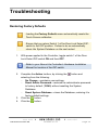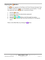
1
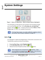
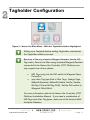
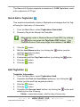
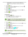
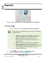
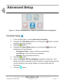
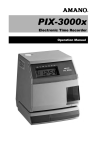
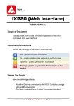
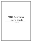
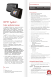
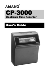
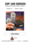
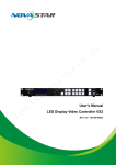
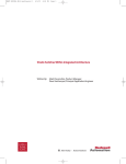
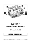
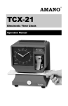
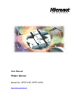
Nexus Lite (Touch Screen) USER MANUAL Scope of Document This document gives a brief overview of operation of the Nexus Lite Controller’s Touch Screen user interface. Document Conventions We use the following conventions in this document: Note – points out extra information Tip – points out alternative methods to perform a task Important – points out important information Warning – points out potential danger to you or the product Before You Begin Ensure you have access to the Nexus Lite Controller. The Nexus Lite Controller (Touch Screen model) also provides access to the Web Interface. To access the Web Interface using this model, ensure you lock the screen and have an active Ethernet connection (using a standard Ethernet cable). For further information please refer to the Nexus Lite Web Interface User Manual. 1 System Settings Figure 1 – Nexus Lite Main Menu – With the System Option Highlighted On initial start-up of the Nexus Lite Controller, the Controller prompts you to set the Date and Time. At the No date set, set date/time? prompt, click the button. Continue from the section Date or Time Setup, page 10, point 2 to complete the process. If, during this process, you notice calibration problems refer to the section Touch Screen Calibration on page 23. Auto-ID For population of tables and identification of Terminals connected on the Terminal Bus, perform an Auto-ID as follows: 1. 2. 3. From the Main Menu, select System>Auto ID. At the Run Auto-ID prompt, click the button. Review the Auto-ID results and then click the button. Units assigned and connected have a indicator. Units unconnected but assigned have a indicator. Units that are unassigned but connected display a indicator. ISC305-0-0-AC-02 October 2010 Page 2 Door Configuration The Nexus Lite System supports a maximum of 8 Doors. Each Door has 3 Door Mode Patterns (each with 4 time period allocations). The Nexus Lite user interface allows for configuration of each Door individually (buttons labeled 1 thorough 8) or configuration across all Doors at once (All button). Add a Door General Settings 1. From the Main Menu, select System>Doors. 2. Click the button representing either a Door number (1 through 8) or alternatively the All option. 3. Click the button. 4. Edit the Door Name textbox, by clicking the button (use the multi-tap keypad provided). 5. Click the button. 6. Add the Door to the Anti-passback (APB) Zone, by selecting the Add to APB Zone checkbox. 7. Select the Disable Door checkbox if required. 8. Click the button. 9. Edit the Entry Reader textbox by clicking the button. Make your selection from the list of displayed Readers. 10. Click the button. 11. Edit the Exit Reader textbox by clicking the button. Make your selection from the list of displayed Readers. 12. Click the button. 13. Click the button. Entry Settings 1. Click the button. 2. Edit the RTE Mode textbox by clicking the include: ISC305-0-0-AC-02 October 2010 button, your options Page 3 Normally Closed—sensor remains closed until opened by an operator. Normally Open—sensor remains open until closed by an operator. 3. Click the button. 4. Edit the DOS Mode textbox by clicking the button, your options include: Normally Closed Normally Open 5. Click the button. 6. Click the button. 7. Edit the DOS Usage textbox by clicking the button, your options include: Normal—alarm sounds if the Door remains open too long or if the Door is forced. Use this feature for monitoring real Door open states. Inhibit—deactivates the Reader as long as the Door is open; also there is no alarm for Doors forced open. Used to disable the reader while the Door remains open. Terminate Strike—deactivates the relay if the Door is opened and closed or forced. Use this feature where the lock must reengage once the Door is closed. 8. Click the button. 9. Complete the Open Duration (in seconds) textbox, by clicking the button (use the keypad provided). This is the amount of time the Door is allowed to remain open before an alarm triggers. By default, the Open Duration is 0, disenabling the Door Open Sensor (DOS). 10. Click the button. 11. Click the button. 12. By default end-of-line sensing is disabled, to enable end-of-line sensing on the Door Open Sensor (DOS), select the Enable DOS Line Sensing checkbox. ISC305-0-0-AC-02 October 2010 Page 4 13. Adjust the Strike Duration (in seconds) textbox, by clicking the button (use the keypad provided). The default strike duration is 4. The maximum Strike Duration is 999 999. 14. Click the button. 15. Click the button. 16. Click the button alongside the Valid Tag Buzzer Volume textbox, select from the options (Off, Soft, Medium and Loud) given. 17. Click the button. 18. Click the button alongside the Invalid Tag Buzzer Volume textbox, select from the options (Off, Soft, Medium and Loud) given. 19. Click the button. 20. Click the button. Exit Settings 1. Click the button. 2. Based on the similarity of the steps involved in Exit Settings, refer to the Entry Settings section (page 3) for more information. Door Mode Pattern Configuration 1. Click the button. 2. Make your selection from the list of available Access Days (Sunday to Saturday or Holidays). 3. Click the button. 4. Complete the Pattern Mode textbox, by clicking the button and selecting from the following: Tag Only—requires presentation of a Tag to open the Door. In this Mode the Reader’s LED is steady Red. Tag + PIN—requires presentation of a Tag followed by entry of a PIN-code to open the Door. PIN-codes range from 2 to 65534. After entering the PIN-code, complete the entry by pressing the # key). In this Mode the Reader’s LED blinks Red then Green. Selecting this mode without connecting a keypad reader, applies Tag Only rules. ISC305-0-0-AC-02 October 2010 Page 5 5. 6. 7. 8. Tag + Reason—requires presentation of a Tag followed by entry of a Reason Code to open the Door. In this Mode, the Reader’s LED blinks OFF then ON in Red. Selecting this mode without connecting a keypad reader, applies Tag Only rules. PAC—requires entry of a Personal Access Code (PAC) to open the Door. Your Personal Access Code may range from between 1 to 9999 followed by a # symbol. In this Mode, the Reader’s LED blinks ON then OFF in Red. Open on First Tag—the door is opened when the first valid Tagholder presents their Tag and remains open. In this Mode the Reader’s LED flashes Green. Open Now—the Door opens at specified time. A Tag is not required to open the Door. In this Mode the Reader’s LED is steady Green. Locked—the Door is locked and cannot be overridden with any Tag. In this Mode the Reader’s LED flashes Red. Click the button. Set the Start and End Time, by clicking the alongside the respective textbox. Select the Hours and Minutes using the buttons. Click the button. Set 3 time periods for a Door open between 8 am and 5 pm, that is: Slot 1—Start Time 00:00 (default), Stop Time 07:59. Slot 2—Start Time 08:00, Stop Time 17:00. Slot 3—Start Time 17:01, Stop Time 23:59. The button only activates once you have indicated a Stop Time of 23:59. 9. Click the ISC305-0-0-AC-02 button. October 2010 Page 6 10. Set any remaining Door Mode Patterns or click the return to the Door Selection Menu. button to Delete a Door 1. From the Main Menu, select System>Doors. 2. Click the button representing the Door for deletion. 3. Click the button. 4. Click the button. 5. In the Entry Reader textbox, click the button. 6. Delete the Door by selecting None from the displayed list. 7. Click the button. 8. In the Exit Reader textbox, click the button. 9. Delete the Door by selecting None from the displayed list. 10. Click the button. 11. Click the button. 12. Click the button to return to the Door Settings Menu. Return to the System Settings Menu by clicking the button. Access Group Setup The Default Access Group allows ALL Tagholders assigned to the Group access to ALL Doors at ALL times. Therefore, create Access Groups to restrict or allow access as required. Add an Access Group 1. From the Main Menu, select System>Groups>Add. 2. Enter a suitable name in the Group Name textbox, by clicking the button (use the multi-tap keypad provided). 3. Click the button. 4. Click the button. 5. Set the Start and Stop Time by clicking the button. 6. Select the Hours and Minutes using the buttons. ISC305-0-0-AC-02 October 2010 Page 7 7. 8. Click the button. Make your selection from the list of available Access Days (Sunday to Saturday or Holidays). 9. Click the button. 10. Make your selection from the displayed Access Doors. 11. Click the button. Delete an Access Group 1. From the Main Menu, select System>Groups>Delete. 2. Select the Group Name for deletion using the buttons. 3. Click the button. 4. Click the button. 5. At the confirmation message, click the button. Edit an Access Group 1. From the Main Menu, select System>Groups>Edit. 2. Based on the similarity of the steps involved in Editing an Access Group, refer to Add an Access Group (page 7) for more information. Return to the System Settings Menu by clicking the button. Holidays Setup Add a Holiday 1. From the Main Menu, select System>Holidays>Add. 2. Enter a suitable name in the Holiday Name textbox, by clicking the button (use the multi-tap keypad provided). 3. Click the button. 4. Set the Start Date by clicking the button. 5. Select the Month using the buttons. 6. Select the Day using the buttons. 7. Click the button. 8. Click the button. 9. Set the End Date by clicking the button. ISC305-0-0-AC-02 October 2010 Page 8 10. Select the Month and Day as shown in points 5 and 6 above. 11. Click the button. 12. Click the button. Delete a Holiday 1. From the Main Menu, select System>Holidays>Delete. 2. Select the Holiday Name for deletion using the buttons. 3. Click the button. 4. Click the button. 5. At the confirmation message, click the button. Edit a Holiday 1. From the Main Menu, select System>Holidays>Edit. 2. Based on the similarity of the steps involved in Editing a Holiday, refer to the section Add a Holiday (page 8) for more information. Return to the System Settings Menu by clicking the button. Reason Code Setup The Nexus Lite System allows for storage of a maximum of 10 Reason Codes, letting you assign any number between 1 and 99 to your Reason Code. This feature allows you to keep legacy Reason Codes and avoid retraining employees. 1. 2. 3. 4. 5. From the Main Menu, select System>Reasons. Enter a number between 1 and 99 in the Code Number textbox, by clicking the button (use the keypad provided). Click the button. Enter a suitable description in the Description textbox, by clicking the button (use the multi-tap keypad provided). Click the button. ISC305-0-0-AC-02 October 2010 Page 9 Scroll between Reason Codes using the buttons. As you move through the Reason Code screens, the screen header indicates the number of the Reason Code in relation to the number allowed by the System. 6. Click the button. Date or Time Setup 1. 2. 3. 4. 5. 6. 7. 8. 9. 10. 11. 12. 13. 14. 15. 16. 17. From the Main Menu, select System>Date/Time. Set the Current Date by clicking the button. Select the Month using the buttons. Select the Day using the buttons. Click the button. Set the Current Time by clicking the button. Select the Hours and Minutes using the buttons. Click the button. Click the button. Set the Daylight Savings Start and End Date by clicking the button. Click the button. Set the Daylight Savings Switch Time by clicking the button. Select the Hours and Minutes using the buttons. Click the button. Select the Shift Duration by clicking the button (use the keypad provided). Click the button. Click the button. Return to the Main Menu by clicking the ISC305-0-0-AC-02 October 2010 button. Page 10 2 Tagholder Configuration Figure 2 – Nexus Lite Main Menu – With the Tagholders Option Highlighted Setting up a Template before adding Tagholders streamlines the Tagholder addition process. Because of the way standard Wiegand Readers handle HID Tag codes, Nexus Lite Sites using standard Wiegand Readers connected to the Nexus Lite Controller (iTRT Platform) can only support one of two options: HID Tags only (set the DIP-switch to Wiegand Open Format) or any other Tag type (that is Slim Tags, Omega Tags, Mifare® Standard, Mifare® Ultralite, FeliCa, Desfire, WriTag 128 and WriTag 2048). Set the DIP-switch to Wiegand 26-bit/44-bit. For more information refer to the Nexus Lite Controller (iTRT Platform) Installation Manual. If you need a combination of HID Tags and other Tag types, make use of the Amano Multidiscipline Readers. ISC305-0-0-AC-02 October 2010 Page 11 The Nexus Lite System supports a maximum of 1 000 Tagholders, each with a maximum of 3 Tags. Quick Add a Tagholder This wizard automatically creates a Tagholder and assigns the first Tag, allowing for rapid entry of information. 1. 2. From the Main Menu, select Tagholders>Quick Add. Present a Tag to the Nexus Lite Controller. Alternatively, enter a Personal Access Code (PAC) by clicking the button alongside the Tag Code / PAC textbox. Your Personal Access Code may range from between 1 to 9999. 3. 4. 5. 6. 7. 8. Click the button. Edit the Last Name textbox, by clicking the button (use the multi-tap keypad provided). Click the button. If necessary edit the Tag Code textbox, by clicking the button. Click the button. Click the button. Add Tagholder Tagholder Information 1. From the Main Menu, select Tagholders>Add. 2. Complete the First and Last Name textboxes, by clicking the button (use the multi-tap keypad provided). 3. Click the button. 4. Click the button. 5. Complete the Access Level textbox, by clicking the button and selecting from the following: Visitor—restricted access, valid for day of issue only. ISC305-0-0-AC-02 October 2010 Page 12 Administrator—overrides Anti-passback (APB) Rules. Normal—employee Tagholder, access restricted by Door Mode. 6. Click the button. 7. If necessary, complete the PIN-code textbox, by clicking the button (use the keypad provided). 8. Click the button. 9. Click the button. 10. Edit the Custom Field Name textbox, by clicking the button (use the multi-tap keypad provided). 11. Click the button. 12. Click the button. Tag Information 1. Click one of the buttons. 2. Click the button alongside the Tag Code textbox. 3. Present a Tag to the Nexus Lite Controller. Alternatively, enter a Personal Access Code (PAC) by clicking the button alongside the Tag Code / PAC textbox. Your Personal Access Code may range from between 1 to 9999. 4. 5. 6. 7. 8. 9. Click the button. Complete the Access Group textbox, by clicking the button and making your selection. Click the button. Complete the Start and End Date requirements using the associated buttons. Select the Month using the buttons. Select the Day using the buttons. Where a Start or End Date don’t apply, select the n/a option from the calendar. 10. Click the ISC305-0-0-AC-02 button. October 2010 Page 13 11. Click the button. Add a Batch of Tags 1. 2. 3. 4. 5. From the Main Menu, select Tagholders>Batch. At the Batch Enrollment screen, click the button. Present each Tag in succession to the Nexus Lite Controller. After enrolling the batch of Tags, click the button. Click the button to return to the Tagholders Menu. Delete a Tagholder or Tag 1. 2. From the Main Menu, select Tagholders>Delete. Select the Tagholder using the buttons. Click the button alongside the Find textbox this lets you enter non-case sensitive search criteria to find the Tagholder for deletion. Alternatively, click the button and present a Tag to the Nexus Lite Controller, the associated Tagholder is then selected, ready for deletion. 3. 4. Click the button. Delete a Tagholder and all the Tagholder’s associated Tags by clicking the button. Alternatively, if you would like to delete just the Tag (keeping the Tagholder enrolled in the System), click the button representing the Tag for deletion. 5. Click the button. Edit Tagholders or Tags 1. From the Main Menu, select Tagholders>Edit. ISC305-0-0-AC-02 October 2010 Page 14 2. Select the Tagholder using the buttons. Click the button alongside the Find textbox this lets you enter non-case sensitive search criteria to find the Tagholder for editing. Alternatively, click the button and present a Tag to the Nexus Lite Controller, the associated Tagholder is then selected, ready for editing. 3. 4. Click the button. Based on the similarity of the steps involved in Editing a Tagholder or Tag details, refer to the Add Tagholder section (page 12) for more information. Template Setup Create a template for Tagholder enrollment as follows: 1. 2. 3. 4. 5. 6. 7. 8. 9. From the Main Menu, select Tagholders>Template. Complete the First and Last Name Prefix textboxes (used with Batch Enrollment), by clicking the button (use the multi-tap keypad provided). Click the button. Click the button. Complete the Access Level textbox, by clicking the button and selecting from the following: Visitor—restricted access, valid for day of issue only. Administrator—overrides Anti-passback (APB) Rules. Normal—employee Tagholder, access restricted by Door Mode. Click the button. Select an Access Group, by clicking the button and selecting a Group from the list. Click the button. Click the button. ISC305-0-0-AC-02 October 2010 Page 15 10. Click the button alongside the Custom Field Name textbox, and enter a field name (for example, Employee Number or Identity Number) using the multi-tap keypad provided. 11. Click the button. 12. Click the button alongside the Custom Field Default textbox, and enter custom information using the multi-tap keypad provided. 13. Click the button. 14. Click the button. 15. Complete the Start and End Date requirements using the associated buttons. 16. Select the Month using the buttons. 17. Select the Day using the buttons. Where a Start or End Date doesn’t apply, select the n/a option from the calendar. 18. Click the 19. Click the button. button. Return to the Main Menu by clicking the ISC305-0-0-AC-02 October 2010 button. Page 16 3 Reports Figure 3 – Nexus Lite Main Menu – With the Reports Option Highlighted View Reports 1. From the Main Menu, select Reports>View>Selected Report*. Replace the term ―Selected Report‖ with one of the following available Reports: 2. 3. Access—this Report provides access data for the selected Tagholder over a specified date range. Status—this Report displays all the status transactions from Controllers and Terminals on a selected date. Audit—this Report provides a list of Tags added, edited or deleted over a specified date range. Hours Worked—this Report calculates hours worked from the IN and OUT Transactions of the Antipassback (APB) Zone. Click the button alongside the Tagholder textbox. Select the Tagholder using the buttons. ISC305-0-0-AC-02 October 2010 Page 17 Click the button alongside the Find textbox this lets you enter non-case sensitive search criteria to find the Tagholder. Alternatively, click the button and present a Tag to the Nexus Lite Controller, the associated Tagholder is then selected. 4. 5. 6. 7. 8. 9. Click the button. Set the Report’s Start and End Date by clicking the Select the Month using the buttons. Select the Day using the buttons. Click the button. Click the button. button. Delete Reports Deleting a Report deletes all the associated transactions. 1. From the Main Menu, select Reports>Delete>Selected Report*. Replace the term ―Selected Report‖ with either Access or Status Report. 1. 2. 3. 4. 5. Set the Start and End Date by clicking the button. Select the Month using the buttons. Select the Day using the buttons. Click the button. At the confirmation message, click the button. Return to the Main Menu by clicking the ISC305-0-0-AC-02 October 2010 button. Page 18 4 Advanced Setup Figure 4 – Nexus Lite Main Menu – With the Advanced Option Highlighted Controller Setup 1. 2. 3. 4. 5. 6. 7. From the Main Menu, select Advanced>Controller. Complete the Site Name textbox, by clicking the button (use the multi-tap keypad provided). Click the button. Complete the Door Mode textbox, by clicking the button and selecting from the following: Emergency Open—opens all Doors immediately. Lock Down—locks all Doors immediately. Normal—Doors operate as set up. Click the button. Select the Enable Off-line Validation checkbox if required. This allows Terminals connected to the Controller to make certain access control decisions even when unable to communicate with the Controller. Click the button. ISC305-0-0-AC-02 October 2010 Page 19 8. Complete the APB Type textbox, by clicking the button and selecting from the following: Strict—enforced Anti-passback Zone rules for in and out directions. A Tagholder cannot enter or exit a Zone consecutively. Relaxed—after entering a Zone, the Tagholder must exit the Zone using their Tag before they can re-enter. However, Tagholders can use their Tags for multiple, consecutive exits in this Mode. 9. Click the button. 10. Select the Reset APB checkbox if required. 11. The Display TFT Transactions checkbox is selected by default, de-select the checkbox to prevent transactions appearing on the Controller’s screen as they occur on site. 12. Click the button. Communications From the Main Menu, select Advanced>Comms. UDP Output The UDP Output feature sends events generated in the Nexus Lite System to a third-party application. Configure this feature as follows: 1. 2. 3. 4. 5. 6. Click the button. Select the Enable UDP checkbox. Complete the Receiving IP Address textbox, by clicking the button (use the keypad provided). Click the button. Click the button. Complete the Receiving Port Number textbox, by clicking the button (use the keypad provided). ISC305-0-0-AC-02 October 2010 Page 20 The default Receiving Port Number is 10010. Only change this if it clashes with other devices or services on your network. 7. 8. Click the button. Complete the Keep-alive Time (in seconds) textbox, by clicking the button (use the keypad provided). The default Keep Alive Time is 60 seconds. This sets the time between signal pulses. 9. Click the button. 10. Click the button. Replace Unit 1. Click the button. 2. Complete the Replace textbox, by clicking the button (using the buttons select a unit Fixed Address for replacement from the displayed list). 3. Click the button. 4. Complete the With textbox referring to the Fixed Address of the replacement unit, by clicking the button (use the multi-tap keypad provided). 5. Click the button. 6. Click the button. After replacing the unit, populate the tables and identify the Terminals connected on the Terminal Bus by performing an Auto-ID. Refer to the Auto-ID section on page 2. Ethernet 1. Click the button. 2. Edit the Device Name textbox, by clicking the multi-select keypad provided). button (use the Type the Device Name into your browser to access the Nexus Lite Web Interface. The default device name is nexuslite. ISC305-0-0-AC-02 October 2010 Page 21 3. 4. 5. 6. 7. 8. Click the button. The Enable DHCP checkbox is selected by default, de-select the checkbox to set a static IP Address for the Controller. Click the button. Complete the Safe IP (Host) textbox, by clicking the button (use the multi-tap keypad provided). Safe IP lets you set a specific IP address for the Nexus Lite Controller to communicate exclusively with. This provides extra security by limiting access points to the System. Click the button. Click the button. The default Web Browser Port Number is 80 and the default Application Port Number is 10005. Only change these if they clash with other devices or services on your network. 9. 10. 11. 12. 13. 14. Complete the Web Browser Port textbox, by clicking the button (use the keypad provided). Click the button. Complete the Application Port textbox, by clicking the button (use the keypad provided). Click the button. Click the button. When prompted to re-start the Controller, click the button. Security Set or change the administrator password as follows: 1. 2. 3. 4. From the Main Menu, select Advanced>Security. Complete the New Code textbox, by clicking the button (use the multi-tap keypad provided). Click the button. Complete the Confirm Code textbox, by clicking the button (use the multi-tap keypad provided). ISC305-0-0-AC-02 October 2010 Page 22 5. 6. 7. 8. Click the button. Click the button. At the confirmation message, click the Click the button. button. Restart 1. 2. From the Main Menu, select Advanced>Restart. At the confirmation message, click the button. Touch Screen Calibration 1. 2. 3. From the Main Menu, select Advanced>Calibrate. At the confirmation message, click the button. Tap the centre of the displayed circle as requested. Return to the Main Menu by clicking the ISC305-0-0-AC-02 October 2010 button. Page 23 Troubleshooting Restoring Factory Defaults Loading the Factory Defaults menu automatically resets the Touch Screen calibration. Ensure that you return Switch 1 of the Door Lock Select DIPswitch to the OFF position. Failure to do so automatically clears the System Database on the next restart. 1. With power applied to the Controller, toggle switch 1 of the Door Lock Select DIP-switch ON and then OFF. Refer to your Nexus Lite Controller’s Hardware Installation Manual for location of the DIP-switch. 2. 3. 4. Complete the Action textbox, by clicking the button and selecting from the following: No Change—maintains user settings. Reset Admin Password—restores the administrator password to factory default (12345) without resetting the System Database. Reset System Database—clears the Database, restoring it to factory default settings. Click the button. Click the button. ISC305-0-0-AC-02 October 2010 Page 24 Clearing the Button The button appears on the Nexus Lite Touch Screen whenever there is a Status event (for example, an anti-tamper) on the System. To view the event and clear the button, continue as follows: 1. 2. 3. 4. 5. Click the button. If necessary, enter the administrator password. Click the button. Using the and buttons, scroll thorough the events. Click the button to clear the events and return to the Reports menu. Return to the Main Menu by clicking the ISC305-0-0-AC-02 October 2010 button. Page 25 Extra Information Further information is available at the following resources: Amano Nexus Lite (Web-based User Interface) User Manual (ISC306-0-0-AC-XX). Amano Nexus Lite Controller Installation Manual (ISC304-0-0-AC-XX). Amano Nexus Lite Firmware Upgrade Utility User Manual (ISC307-0-0-AC-XX). Download the Amano Nexus Lite Firmware Upgrade Utility from the following URL: www.amano.com/access/downloads/Nexus Lite/nexuslitefirm.exe. User Notes ISC305-0-0-AC-02 October 2010 Page 26 User Notes ISC305-0-0-AC-02 October 2010 Page 27 Security Systems Division 180 Alt. 19, Suite A, Palm Harbor, FL 34683 Technical Support: (800) 390 5837 Corporate Headquarters 140 Harrison Avenue, Roseland, NJ 07068-1239, (800) 526-2559 www.amano.com This manual is applicable to the Nexus Lite Touch Screen Interface V 2.10. (The last two digits of the Amano stock code indicate the issue status of the product). ISC305-0-0-AC-02 ISC305-0-0-AC-02 Issue 03 Oct 2010 October 2010 20\Software|\Amano USA\LATEST ISSUE\NexTFT-swm-en-03.docx Page 28