1
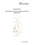
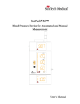
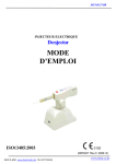
WWW. .COM REF 90500 BATTERY MUST BE CHARGED BEFORE INITIAL USE. STANDARD IMAGING, INC. 7601 Murphy Drive Middleton, WI 53562-2532 TEL 800.261.4446 TEL 608.831.0025 FAX 608.831.2202 Aug / 2006 ©2006 Standard Imaging, Inc. DOC #80471-07 General Precautions WARNING: Electrical shock hazard when connected to 300 V bias supply. Do not disassemble the QA BeamChecker. CAUTION: Proper use of this device depends on careful reading of all instructions and labels. CAUTION: This device should never be submerged in any liquid, scrubbed with an abrasive cleaner, or be stored or placed where liquids could be spilled or splashed onto it. Warnings and Cautions alert users to dangerous conditions that can occur if instructions in the manual are not obeyed. Warnings are conditions that can cause injury to the operator, while Cautions can cause damage to the device and internal electronics. CAUTION: To help ensure measurement reproducibility over time and minimize possible backscatter effects from the treatment couch, especially for low energy photons, position the device in the same location on the treatment couch for every measurement. CAUTION: Do not drop, mishandle, or disassemble this device. Refer all servicing to qualified individuals. CAUTION: Do not irradiate this device past the 20 x 20 cm field label edge. CAUTION: Always use the QA BeamChecker in the same orientation during Baseline Setup, Wire-Free, or Real-Time Operation Modes. Improper comparative measurements and/or out of tolerance error messages will occur if used in a different orientation. Table of Contents PAGE 2 3 3 4 General Precautions Table of Contents Overview Installing the Communications Software 5 Definition of QA BeamChecker Algorithms 6 Device Description 7 Entering Institution / Accelerator Information 8 Setup / Acquiring Baselines 11 Wire-Free Operation 12 Status Interface Description 13 Real-Time Operation Mode 15 Data View Interface 16 Interfacing with Optional Gantry Mount 17 Troubleshooting 18 Maintenance 19 Parts and Accessories 19 Description of Symbols 7601 MURPHY DRIVE MIDDLETON, WI 53562-2532 USA WWW.STANDARDIMAGING.COM 20 22 23 23 24 Explanation of Saved File Export Features and Specifications Service Policy Customer Responsibility Warranty Overview The QA BeamChecker is a reliable and uncomplicated device for daily quality assurance testing of linear accelerator output. It assists medical physicists in verifying that the constancy, symmetry, and flatness of an accelerator beam are not changing over time. The QA BeamChecker consists of the standalone detector unit, a Power/Data Cradle, and PC-based software for baselining the current accelerator parameters and viewing data in real-time. The physicist initially “baselines” each accelerator energy, using the included software. This stores a picture of the current beam constancy, flatness and symmetry, and generates a unique identifier for each energy. This energy identifier is the key for later standalone operation of the QA BeamChecker. After initially creating baselines by connecting the QA BeamChecker and using the accompanying software, no cables are required and no software is needed to run the unit. In daily use, the QA BeamChecker is simply placed back on the treatment couch at the baselined setup parameters, typically a field size of 20 cm x 20 cm and a SSD of 100 cm. Accelerator energies may be selected in any order, and temperature and pressure corrections are automatically made. A unique flip feature is used to measure both photons and electrons. Initially, the photon side may be faced toward the beam, which provides 3.5 cm of water-equivalent buildup. To measure electrons, the unit is simply flipped over, and one button on the front of the unit is pushed to Overview Continued indicate the change and to invert the display. Now 1.5 cm of water-equivalent buildup is present between the beam and the detectors. No other buildup or trips into the treatment vault are typically required. Following a measurement, the QA BeamChecker identifies the energy of the beam that was just used. It then applies this key to look up the expected parameters for that beam energy, and compares them with the present readings. Daily measurements that fall within the physicist-selected acceptance parameters result in a green light displaying on the front panel of the device for about 10 seconds, followed by the unit rearming itself for the next measurement. All data is stored on the QA BeamChecker for later downloading. Measurements outside acceptance parameters cause a red light to flash, an audio alert to sound, and require the Reset button to be pushed on the front of the unit to go on. Additional information is also presented on the large alphanumeric display on the front of the unit. About one month’s worth of data can be stored on the QA BeamChecker before downloading is required, although this may be done at any time. The Power/Data Cradle provides the link to the computer’s RS-232 port, and the included software makes downloading and trending the data quick and easy. The simple three tab interface guides the Physicist through all the steps needed to download data, and indicate the energy and time window of interest. Values for flatness, symmetry, and constancy are graphically displayed for analysis and review. Data can be viewed in graph or table form, and can easily be printed for archiving, if desired. Installing the Communications Software The QA BeamChecker Communications Software is designed to operate under Windows® Me, NT 4.0, 2000 and XP operating platforms. Before installing the software, it is recommended to close all other active programs. Insert the program CD-ROM into your computer's CD-ROM drive. If autorun is enabled, the Installshield Wizard will begin automatically. If autorun is disabled, browse to the program disc in Explorer and double-click setup.exe to start the installation program. Read through the software license agreement and click next to proceed with the installation. A QA BeamChecker Communications Software program icon is placed within the Start Menu under the Standard Imaging program group. If prompted, restart your computer to begin using the QA BeamChecker Communications Software. System Requirements Operating System Processor Memory Hard Drive Screen Resolution CD-ROM Drive Other Microsoft Windows® Me / NT 4.0 SP 6 / 2000 / XP Intel or AMD 350 Mhz or greater 64 MB or greater 30 MB or greater 1024 x 768 or greater 2X speed or greater 1 available serial port Windows is a registered trademark of Microsoft Corporation. Definition of QA BeamChecker Algorithms where: time t = time at which new constancy measurement is being taken time t0 = time at which initial benchmark value was time top (Values are shown in percent.) left center right Flatness: Flatness is determined by using the following algorithm on the raw data values collected from the indicated ion chambers: bottom Photon / Electron Figure 1: Locations identified are ionization chambers embedded in QA BeamChecker. Temperature and Pressure Correction: For constancy measurements and comparison with values measured on subsequent times/days, a temperature and pressure correction is made to the reading of the Center chamber: where: Mcorr = the corrected reading of the Center Ion Chamber Mraw = the raw or uncorrected reading of the Center Ion Chamber T = temperature in ° Celsius measured by on-board temperature sensor P = pressure in Torr measured by onboard pressure sensor Constancy: Constancy is determined by using the following algorithm on the temperatureand-pressure-corrected values from the center ion chamber over time: Flatness = (Max - Min)/(Max + Min) where: Max = the maximum value of Center, Top, Bottom, Right, and Left Min = the minimum value of Center, Top, Bottom, Right, and Left (Values are shown in percent.) Axial Symmetry: Axial symmetry is determined by using the following algorithm on the raw data values collected from the indicated ion chambers: Axial Symmetry = (Top - Bottom)/ (Bottom) (Values are shown in percent.) Transverse Symmetry: Transverse symmetry is determined by using the following algorithm on the raw data values collected from the indicated ion chambers: Transverse Symmetry = (Right Left)/(Left) (Values are shown in percent.) Constancy = (Center (at time t) - Center (at time t0 ))/Center (at time t0 ) Device Description QA BeamChecker Electron Configuration Power On Button Turns the unit on or off. Energy Selection Pressing the E button toggles the unit to electron mode or photon mode. The blue LED will indicate the currently selected energy. Status LED: Displays green when an energy is successfully detected, displays red when an error occurs or energy is detected outside of benchmarks. Status Display: Displays detected energy, error codes, and more information. (See page 8) Ready/Reset Button If the Status Light shows red an error is indicated. This button must be pressed to resume unit operation, acknowledging the error. Power Indicators: Green LED indicates power is on. Amber LED indicates the battery is currently charging. QA BeamChecker Photon Configuration Power/Data Cradle Description Serial Connection to other device or QA BeamChecker (Male) QA BeamChecker Connection External Power Adapter NOTE: Always place the QA BeamChecker on the Power/Data Cradle when not in use to ensure full battery charge. Serial Connection to PC (Female) Entering Institution / Accelerator Information When loading the QA BeamChecker Communications Software for the first time, a dialog box will appear as shown to the right. This information will help associate an installation with a given linear accelerator and it's accompanying QA BeamChecker. It will also appear on each of the three program tab screens: Data View, Real-Time Operation, and Baseline Setup. To edit this information, click in the institution black bar on any tab screen and the dialog box to the right will reappear. Make any desired changes and click Ok to accept or Cancel to discard. This information will also appear on the printouts created by the QA BeamChecker Communications Software. When connecting to the QA BeamChecker in Real-Time Operation or Data View Modes, the serial number entered must match that of the connected unit for a data transfer to take place. If they do not match, an error will occur. Verify your serial number was entered correctly. If a QA BeamChecker is attached to your PC when the software is initially loaded, the serial number will automatically be downloaded from the unit and placed in this field. Figure 2: Institution / Accelerator Information Dialog Box. Setup / Acquiring Baselines The QA BeamChecker is designed to be a simple to use device, yet provide the user with a powerful tool to ensure the quality of their linear accelerator beam. As such, configuring and using the device is easy and requires only a few operations to be ready to use on a daily basis. First, install the communications software as shown on page 4. Upon launching the program for the first time, a form will appear asking for your institution and linear accelerator information. (See page 7) In order to begin using the QA BeamChecker, for each energy to be tested, a Baseline Energy must be created. A baseline is a benchmark that is created to compare your beam to when using Wire-Free or RealTime Operation. (See pages 11 and 13 respectively) When setting baselines, the unit must be attached via serial port to the computer with the communications software installed (See Figure 3). 1] Choose whether you will be measuring photons or electrons. If using electrons ensure a 20 x 20 cm electron cone is attached to the accelerator. QA BeamChecker Treatment Couch RS-232 Cable Bunker Power/Data Cradle Computer Control Room Figure 3: The bold line shows a typical connection between the QA BeamChecker and a computer, using two RS-232 cables. 3] If you have not already done so, connect the QA BeamChecker to the PC as shown in Figure 3. Note that the cradle can be bypassed altogether by using the connections on the QA BeamChecker if desired, but its use is recommended for convenience during operation or while charging the battery. 2] Place the QA BeamChecker on the treatment couch at 100 cm SSD with a field size of 20 x 20 cm. Align the unit to the center of the field using the QA BeamChecker fiducials and the room alignment lasers. NOTE: Verify the QA BeamChecker is flipped to the proper side up and that the blue LED on the front panel matches your selection. Press the "E" button to change this setting. When taking baseline measurements, ensure the QA BeamChecker is in the same orientation (rotated in the same direction on the couch) that will be used for future Wire-Free and Real-Time Operations. To create a baseline, go to the 'Baseline Setup' tab in the communications software. The status light in the upper left corner of the display will show whether the QA BeamChecker is properly attached and ready for measurement. If the unit is found, the status light will display green and read 'Ready'. If not, the light will display red and Setup / Acquiring Baselines Continued Figure 4: Baseline Setup Interface. read 'Not Connected'. Check all connections and try again. (See Troubleshooting section for more information) The QA BeamChecker will automatically turn on when the communication software makes a connection. 1] Under Choose Action, select a new energy to baseline from the pull down menu. All possible energies are displayed with electrons being labeled as MeV and photons as MV. with the current temperature and pressure values will be shown. If satisfied with the baseline acquired, fill in the remaining fields in the 'Energy Baseline Setup Parameters' box. See below for a description of parameters: NOTE: You will not be permitted to fill in these fields until an energy has been detected by the software. 2] Set your accelerator to the desired energy, dose value, and rate. Typical dose value is 100 MU with a rate of 400 MU/min. Gantry Angle: Default is 0 3] Irradiate the unit. SSD (Source to Surface Distance): Default is 100 cm 4] The software status bar will change to reflect the unit is retrieving data, and after a brief moment measured values will appear on the representation of the QA BeamChecker's alignment field. Additionally, the flatness, axial symmetry, transverse symmetry, along Field Size (x,y): Default is 20,20 cm Dose: Configured dose value of the beam Dose Rate: Configured dose rate of the beam Setup / Acquiring Baselines Continued Baseline Date: Date baseline was taken (automatically filled in by the software) Action Levels represent the points at which a flatness, axial symmetry, transverse symmetry, or constancy 'out of tolerance' will occur during measurement in Real-Time Operation or Wire-Free Mode. If a measured energy differs by or more than the percentage entered in 'Action Level 1' box, a level 1 'out of tolerance' will occur. Likewise, if a measured energy differs at or above the percentage entered in 'Action Level 2' box, a level 2 'out of tolerance' will occur, with Action Level 2 occurring at a greater percent difference. Default setting is Action Level 1 at 3% and Action Level 2 at 5%. Baseline Measured By: The name or initials of the baseline creator. up should be labeled as photon or electron as desired. Ensure that the blue LED on the front panel matches the desired energy, this can be switched by pressing the "E" button on the front panel. The 3 character display should also show in the proper orientation. NOTE: Due to the unique nature of each linear accelerator's baselines, the QA BeamChecker should only be used to monitor the performance of a single accelerator. Modifying an Existing Baseline On the Baseline Setup tab, select the desired energy from the Edit Energy Baseline pull-down menu. The previously recorded information will appear in the fields below. When the status reads Ready, irradiate the unit again and re-enter the Energy Baseline Setup Parameters. Once all informational fields have been filled in, select Save to store these parameters. The unit will then reset, ready for the next energy to baseline. Repeat these steps for as many energies as desired. NOTE: Verify the QA BeamChecker is flipped to the proper side. The side facing When modifying the baseline, the measurement must be retaken to edit the parameter information. This is to avoid altering the presentation of data previously acquired under the current baseline measurement. Wire-Free Operation Unique to the QA BeamChecker is the ability to quickly check beam consistency without the required use of the wires or software. Once you have acquired the desired baseline energies as explained on pages 8-10, the unit is ready for measurement versus these benchmarks. sure a 20 x 20 cm electron cone is attached to the accelerator. 1] Choose whether you will be measuring photons or electrons. If using electrons en- NOTE: Verify the QA BeamChecker is flipped to the proper side. The side facing 2] Place the QA BeamChecker on the treatment couch at 100 cm SSD with a field size of 20 x 20 cm, ensuring the alignment lasers match the field size. 10 Wire-Free Operation Continued up should be labeled as photon or electron as desired. Ensure that the blue LED on the front panel matches the desired energy, this can be switched by pressing the "E" button on the front panel. The 3 character display should also show in the proper orientation. When operating in the Wire-Free Mode, ensure the QA BeamChecker is in the same orientation (rotated in the same direction on the couch) that was used when baseline measurements took place. 3] Adjust the bunker camera so that the front panel display of the QA BeamChecker is clearly visible on the patient monitor. See page 6 for a detailed explanation of the front panel layout. 4] Set the linear accelerator for the energy you wish to test and make sure the status light on the front panel shows green and reads RdY. 5] Irradiate the unit. When radiation is detected by the QA BeamChecker, the front panel will display *** with animating stars. 6] Check the patient monitor to see if the energy was successfully detected. If the energy was measured within an acceptable percentage set by the Action Levels chosen during Baseline creation, the status light will glow green with accompanying single beep. Furthermore, the detected energy will display on the unit for approximately 10 seconds. For example, 06E for a 6 MeV electron detection, or 12X for a 12 MV photon detection. The measurement is saved in the QA BeamChecker's internal memory for future upload to the software database. the unit is flipped to the photon or electron side as desired. In the event that a measured energy falls out of range of a preset baseline, the status light on the front panel will glow red and blink slowly for an action level 1 error and more quickly for an action level 2 error with a corresponding beeping sound. (See page 5 for a description of action levels) Additionally, the front panel will display: ASM TSM FLT CST axial symmetry 'out of tolerance' transverse symmetry 'out of tolerance' flatness 'out of tolerance' constancy 'out of tolerance' This error is recorded in the QA BeamChecker's internal memory to be displayed in the database in a future upload. In order to proceed to the next measurement, the error must be acknowledged by entering the treatment room and pressing the 'ready/reset' button on the front panel of the QA BeamChecker. NOTE: To ensure the QA BeamChecker is always charged and ready to use, return the unit to its cradle after measurements are completed. 7] The QA BeamChecker will automatically re-arm itself and is ready for the next detection. Simply wait until the status light glows green and RdY displays. No other preparation is necessary. Repeat steps 1-6 for as many energies as desired, ensuring 11 Status Interface Description Description of QA BeamChecker Status Display Codes When selecting mode of operation with the 'E' button on the front panel, the currently selected mode will display briefly. Showing PHO for photon and ELE for electron the display will flip orientation if changed. When an energy is detected, the front panel will display its value. Photon is represented by 2 numbers followed by an X and electron followed by an E. When the QA BeamChecker is ready for a measurement, RdY will display on the unit. While irradiating the unit, spinning stars will display indicating data collection is taking place. This code will display if an unknown energy is detected. No benchmark for detected energy. When an 'out of tolerance' occurs, one or more of the following 4 codes will display: Axial Symmetry 'out of tolerance' If operating the unit in Real-Time Operation Mode, WTG will display after a measurement until the user decides to save or discard the acquired data. Transverse Symmetry 'out of tolerance' Flatness 'out of tolerance' Constancy 'out of tolerance' Status LED & Ready/Reset Button Information The status LED is designed to be a quick indicator of the QA BeamChecker's current state. Below is a list of possible status displays and what they indicate. Green (Solid): A successful measurement has been taken and unit is ready for the next energy reading. A single loud tone will occur, no action is required. Red (Single repeated flash): A Level 1 error has occurred, check the display for status code. The Ready/Reset button must be pressed to continue. Red (Double repeated flash): A Level 2 error has occurred, check the display for status code. The Ready/Reset button must be pressed to continue. 12 Real-Time Operation Mode Figure 5: Real-Time Operation Mode The QA BeamChecker can also be used when connected to the PC for an expanded interface using the communications software. 1] Choose whether you will be measuring photons or electrons. If using electrons ensure a 20 x 20 cm electron cone is attached to the accelerator. 2] Place the QA BeamChecker on the treatment couch at 100 cm SSD with a field size of 20 x 20 cm, ensuring the alignment lasers match the field size. NOTE: Verify the QA BeamChecker is flipped to the proper side. The side facing up should be labeled as photon or electron as desired. Ensure that the blue LED on the front panel matches the desired energy, this can be switched by pressing the "E" button on the front panel. The 3 character display should also show in the proper orientation. When operating in the Real-Time Operation Mode, ensure the QA BeamChecker is in the same orientation (rotated in the same direction on the couch) that was used when baseline measurements took place. 3] Attach a serial cable running straight to the PC or through the cradle 'passthru' port. Confirm that the status bar indicates the unit is ready, and the QA BeamChecker will automatically power on. 4] Set your linear accelerator for the desired energy and irradiate the unit. Similar to WireFree mode the detected energy value will appear. In addition, the baseline parameters will appear to the right of the detected energy for reference. Calculated values, along with the current temperature and pressure, will appear on the representation of the QA BeamChecker measurement field. Within the Calculated 13 Real-Time Operation Mode Continued Values box, column 1 represents values calculated from the present measurement, while column 2 represents of the percent difference from the acquired baseline. If all measurements fall within accepted values, the status indicators in the final column will all show green. If a measurement falls outside of the accepted benchmark percentages, the status indicators show the action level recorded. Yellow represents action level 1 and red indicates action level 2. Click yes to save to database or no to proceed to the next measurement without saving. Figure 6: Real-Time Operation status boxes WTG will display on the QA BeamChecker front panel after a measurement is taken until the user decides to save or discard the acquired data. NOTE: To ensure the QA BeamChecker is always charged and ready to use, return the unit to its cradle after measurements are completed. 14 Data View Interface Figure 5: Data View showing an acquired 6 MV energy (Graph View) When data has been acquired by the QA BeamChecker in either Wire-Free or RealTime Operation modes, selecting the Data View tab allows you to view that data in detail. If data has been acquired in the Real-Time Operation mode, that is, used while the QA BeamChecker is connected to the PC through a serial connection, then this data is already part of the database. To download data from the QA BeamChecker unit after a Wire-Free data acquisition, follow these steps: 1] Place the QA BeamChecker on the Power/Data Cradle while connected to the PC. 2] Enter the Data-View screen by clicking on the appropriate tab at the top of the screen. 3] The status indicator will show green and that the unit is ready for data transfer. The download data button will change to show the QA BeamChecker in full color if there is new data to retrieve. Press it to synchronize the data stored in the QA BeamChecker's internal memory with the database stored on the PC. A status bar will appear showing that a transfer is taking place. When the transfer is complete, the data can be viewed by energy. In the View Energy box, use the pull down menu to select an acquired energy from the list. The energy and type will appear along with the energy setup parameters that were specified at the time of baseline creation. Select the Graph Range Begin Date and End Date to view the data over the desired time period on the graph representing time versus percent error. See Figure 5 for an example of data shown in Graph View. To view the data in tabular format, click the Table View button to the left of the graph. See Figure 6 for an example of data shown in Table View. 15 Data View Interface Continued Figure 6: Data View showing an acquired 6 MV energy (Table View) The colors shown on the table indicate how close the acquired values are to the baseline. Just like the status indicators found in the Real-Time Operation mode, the colors of the cells indicate whether the energy is within the accepted range of the baseline (green), outside of the range by the amount specified by action level 1 (yellow), or outside the range specified by action level 2 (red). The graph and a summary of the table view can be printed to the default printer by pressing the [ Print ] button. By pressing the [ Export ] button, the table data is exported to a .csv file for opening in most spreadsheet applications. See page 20 for a detailed explanation of export file format. NOTE: It is not required to download acquired data from the QA BeamChecker after every Wire-Free session. The QA BeamChecker internal memory will hold up to 256 measurements before the data will need to be transferred to the software database. Interfacing with Optional Gantry Mount Using an optional accessory P/N 70500, the QA BeamChecker can interface with the gantry mount on most linear accelerators. Contact Standard Imaging for information about your particular accelerator and if we can provide an accompanying custom gantry mount for your QA BeamChecker. Standard Imaging, Inc. 7601 Murphy Drive Middleton, WI 53562-2532 USA Tel: 608-831-0025 Toll-Free: 800-261-4446 Fax: 608-831-2202 http://www.standardimaging.com 16 Troubleshooting Refer to the following scenarios if you are experiencing problems with your QA BeamChecker. Before contacting Standard Imaging, read this section to potentially resolve an issue without sending your device in for service. Possible Cause 2: The COM port is not properly configured in Microsoft Windows or the system BIOS. Refer to your operating system/computer user manual or contact the manufacturer of your computer for more information. Scenario 1: The QA BeamChecker will not respond to commands on the front panel or through Real-Time Operation Mode. Possible Cause 3: The QA BeamChecker is not turned on. The communications software will automatically detect any connected QA BeamChecker and power it on. If all data connections are present, make sure that the AC power is supplied to the cradle in the event of a low battery. Possible Cause 1: The QA BeamChecker is not powered on. Press the power on/ off button on the front panel of the device. Possible Cause 2: The internal battery is low or dead. Either place the device onto the cradle, or attach the AC adapter directly to the QA BeamChecker. Use only with Globtek®, Inc. power supply model GTM21089-1509-T3 9VDC @ 1.7A RS232 Possible Cause 3: The interface has 'frozen up'. Press the pinhole reset switch on the side of the unit. This will only reset the unit, the internal memory is not erased. reset Scenario 2: The QA BeamChecker is shown as 'Not Connected' by the communications software in Real-Time Operation or Baseline Setup Modes. Possible Cause 1: The QA BeamChecker is not properly resting on the cradle or cable is not attached to the PC. Make sure the unit has been firmly placed on the cradle and confirm all cables between the cradle and PC or the QA BeamChecker and PC are properly inserted. Scenario 3: There is no logical place to connect the QA BeamChecker or cradle to my PC. Possible Cause 1: Your computer does not have a serial port. Some laptops or small form factor computers do not have a serial port built-in. Several 3rd party companies manufacture adapters which allow you to connect a serial device through a USB port. If you do not have an available USB connection, try a PCI serial port addon card. Consult your computer manufacturer for more information. Possible Cause 2: All available serial ports are full on my PC. See Cause 1 for possible solutions. Scenario 4: When taking measurements in Wire-Free mode, error code 'XXX' appears on the QA BeamChecker front panel status display. Possible Cause 1: A baseline has not been acquired for the detected energy. Make 17 Troubleshooting Continued sure a baseline measurement has been acquired for the energy you are attempting to measure. See page 6 for instructions on how to create baselines. Possible Cause 2: The QA BeamChecker is not flipped to the proper side or the E switch has not been pressed to indicate a flip. Ensure that the proper side faces up on the QA BeamChecker when placed on the treatment couch. The text on the field label should match the desired energy. Also the blue light on the front panel should match the desired type, either photon or electron, and the status display will be orientated in the correct direction. Possible Cause 3: The QA BeamChecker is not rotated in the same direction on the couch that it was placed when baseline measurements were taken. Although the field shape on the surface of the QA BeamChecker is symmetrical, the unit must be consistently used in the same orientation from baseline measurement to Wire-Free or RealTime Operation Modes. on the QA BeamChecker front panel status display. Possible Cause 1: An internal hardware failure has occurred. Turn off the QA BeamChecker and turn it back on to see if this error clears. If not, press the pinhole reset switch on the side of the unit. If the error is still not cleared, contact Standard Imaging for service. Have the error code(s) ready when explaining the problem to one of our service technicians. Below is a list of internal hardware value codes and what problem they indicate: E01 E02 E03 E04 E05 E06 E07 E08 Bias EEPROM Display Driver Barometer/Temperature Module A/D Real time clock Low Battery Internal Memory Full Scenario 5: Error code E(01-15) shows Maintenance Exterior cleaning of the device can be done with a soft brush and a cloth. Gently brush all surfaces to remove dirt and dust. Be especially careful that this is an external cleaning only and do not permit any liquid to seep into the QA BeamChecker in any manner during cleaning. There are no user serviceable parts on the QA BeamChecker. The warranty will become void if the QA BeamChecker is disassembled. If assistance is desired in the proper disposal of this product (including accessories and components), after its useful life, please return to Standard Imaging. 18 Parts and Accessories REF Description 90500 80471 70500 70501 70502 70503 QA BeamChecker User's Manual Linear Accelerator Gantry Mount (varies by accelerator model) QA BeamChecker Communications Software QA BeamChecker Power/Data Cradle Optional Serial to USB Adapter Description of Symbols The following symbols are found on the QA BeamChecker: Power On/Off Switch Dangerous Voltage Present Inside Enclosure Attention, Consult Accompanying Documents Signal Input Battery Charge Level Reset Energy Selection Switch Return to Ready/ Reset Switch Sound/Speaker Power On 19 Explanation of Saved File Export When exporting data from the QA BeamChecker Communications Software, the default file type is a *.csv file, (comma separated value), that can be directly opened with any spreadsheet application. The resulting file will have data labels as described below. Baseline data and Measurement data are separated by several rows, and have different column headers, as listed. Baseline Data: Column Data Label Description A unique identifier for the baseline energy that incorporates date and time of measurement Collimator size, as entered in the Baseline Setup screen Source to Surface Distance, as entered in the Baseline Setup screen Linear accelerator dose rate, as entered in the Baseline Setup screen Linear accelerator dose, as entered in the Baseline Setup screen Gantry angle, as entered in the Baseline Setup screen Temperature when baseline measurement was taken, in °C Pressure when baseline measurement was taken, in mm Hg A (1) BASELINE_ID B (2) FIELD_SIZE C (3) SSD D (4) DOSERATE E (5) DOSE F (6) GANTRYANGLE G (7) TEMPERATURE H (8) PRESSURE I (9) ENERGYLEVEL A unique identifier for the baseline energy as determined by several ionization chambers and a proprietary algorithm J (10) (BLANK) Intentionally left blank K (11) AXSYM Axial symmetry of baseline energy, calculated from the ionization chamber readings L (12) TRSYM Transverse symmetry of baseline energy, calculated from the ionization chamber readings M (13) FLATNESS Flatness of baseline energy, calculated from the ionization chamber readings N (14) CENTER_RAW O (15) LTP_RTE_RAW P (16) TOP_RAW Data collected from the top ionization chamber during the baseline measurement Q (17) RTP_LTE_RAW Data collected from the right (photon side) or left (electron side) ionization chamber during the baseline measurement R (18) BOTTOM_RAW Data collected from the bottom ionization chamber during the baseline measurement S (19) NUM_SAMPLES Number of samples collected by the microprocessor during the baseline measurement Data collected from the center ionization chamber during the baseline measurement Data collected from the left (photon side) or right (electron side) ionization chamber during the baseline measurement 20 Explanation of Saved File Export Continued Measurement Data : Column Data Label Description A (1) BASELINE_ID Identifies which baseline energy values were chosen for comparison to the measurement data B (2) DATE Date when measurement was taken, in the format mmddyyyy C (3) TIME Time when measurement was taken, in the format hhmmss D (4) (BLANK) Intentionally left blank E (5) (BLANK) Intentionally left blank F (6) (BLANK) Intentionally left blank G (7) TEMPERATURE Temperature when measurement was taken, in °C H (8) PRESSURE Pressure when measurement was taken, in mm Hg ENERGYLEVEL An unique identifier for the energy as determined by several ionization chambers and a proprietary algorithm. This is then compared to the set of ENERGYLEVEL values from baselines above J (10) CONSTANCY Constancy of measured energy, calculated from the center ionization chamber compared to baseline center ionization chamber value K (11) AXSYM Axial symmetry of measured energy, calculated from ionization chamber readings L (12) TRSYM Transverse symmetry of measured energy, calculated from ionization chamber readings M (13) FLATNESS Flatness of measured energy, calculated from ionization chamber readings N (14) CENTER_RAW Data collected from the center ionization chamber during the measurement O (15) LTP_RTE_RAW P (16) TOP_RAW Q (17) RTP_LTE_RAW R (18) BOTTOM_RAW S (19) NUM_SAMPLES I (9) Data collected from the left (photon side) or right (electron side) ionization chamber during the measurement Data collected from the top ionization chamber during the measurement Data collected from the right (photon side) or left (electron side) ionization chamber during the measurement Data collected from the bottom ionization chamber during the measurement Number of samples collected by the microprocessor during the measurement 21 Features and Specifications Dimensions QA BeamChecker: Length: Width: Height: 16.00 in (40.64 cm) 12.15 in (30.86 cm) 2.42 in (6.15 cm) Cradle: Length: Width: Height: 11.50 in (29.21 cm) 4.00 in (10.16 cm) 2.82 in (7.16 cm) Weight: QA BeamChecker: Cradle: 14 lbs (6.4 kg) 4 lbs (1.8 kg) 8 Vented Ionization Chambers (Fully Guarded): Chamber Volume: Parallel Plate Separation: Collection Electrode: One center detector Four quadrant detectors, 8.6 cm from center Three energy identification chambers 0.6 cm3 4.0 mm 1.39 cm diameter Inherent Buildup: Photon Side: Electron Side: 3.5 cm water-equivalent material 1.5 cm water-equivalent material Light Field Alignment: 20 cm x 20 cm alignment grid Radiation Measured: Photons: Electrons: Co-60 to 25 MV 6 MeV to 25 MeV Time and Date: Real-time clock on board provides time and date stamp to all data Stores up to 256 data points before transfer required Memory Capacity: Temperature and pressure measurement: (Precision sensor on board) Pressure Resolution: 0.1 mm Hg Temperature Resolution: 0.1°C Operating Parameters Temperature: Relative Humidity: Pressure: 10 to 40 °C 20 to 80% non-condensing 650 to 770 mmHg Storage Parameters Temperature: Relative Humidity: Pressure: -15 to 50 °C 10 to 95% non-condensing 600 to 800 mmHg Power Requirements: Battery: Battery Recharge Time: Charger Input: Product Standards: - 1 1.3 Ah SLA, 4 hours of continuous use Approximately 8 hours from full discharge 90 – 240 VAC, 50-60 Hz, EN/IEC 60601-1 approved power supply, Globtek®, Inc. model GTM21089-1509-T3 IEC 60601-11, IEC 60601-1-21 Authorized representative for the EU is AMA, Ltd., St. Felix House, Flitcham, King’s Lynn, Norfolk, United Kingdom, PE31 6BU. Externally Certified - - Competent Authority for the EU is the Medical Products Agency, Sweden. Notified Body for the EU is Semko, Sweden. Specifications are subject to change without notice. 22 Service Policy Customer Responsibility If service, including recalibration, is required, please contact Standard Imaging’s Customer Service department by phone or email prior to shipping the product. Standard Imaging’s Customer Service and Technical Service staff will attempt to address the product issue via phone or email. If unable to address the issue, a return material authorization (RMA) number will be issued. With the RMA number, the product can be returned to Standard Imaging. It is the responsibility of the customer to properly package, insure and ship the product, with the RMA number clearly identified on the outside of the package. The customer must immediately file a claim with their carrier for any shipping damage or lost shipments. Return shipping and insurance is to be pre-paid or billed to the customer, and the customer may request a specific shipper. Items found to be out of warranty are subject to a minimum service fee of 1 hour labor (excluding recalibrations) for diagnostic efforts and require a purchase order (PO) before service is performed. With concurrence from customer, the product may be replaced if it is unserviceable or if the required service is cost prohibitive. Products incurring service charges may be held for payment. Standard Imaging does not provide loaner products. See the Standard Imaging Warranty and Customer Responsibility for additional information. This product and its components will perform properly and reliably only when operated and maintained in accordance with the instructions contained in this manual and accompanying labels. A defective device should not be used. Parts which may be broken or missing or are clearly worn, distorted or contaminated should be replaced immediately with genuine replacement parts manufactured by or made available from Standard Imaging Inc. Serialization Information Standard Imaging products that are serialized contain coded logic in the serial number which indicates the product, day and year of manufacture, and a sequential unit number for identification: CAUTION: Federal law in the U.S.A. and Canadian law restrict the sale, distribution, or use of this product to, by, or on the order of a licensed medical practitioner. The use of this product should be restricted to the supervision of a qualified medical physicist. Measurement of high activity radioactive sources is potentially hazardous and should be performed by qualified personnel. Should repair or replacement of this product become necessary after the warranty period, the customer should seek advice from Standard Imaging Inc. prior to such repair or replacement. If this product is in need of repair, it should not be used until all repairs have been made and the product is functioning properly and ready for use. After repair, the product may need to be calibrated. The owner of this product has sole responsibility for any malfunction resulting from abuse, improper use or maintenance, or repair by anyone other than Standard Imaging Inc. The information in this manual is subject to change without notice. No part of this manual may be copied or reproduced in any form or by any means without prior written consent of Standard Imaging Inc. A YY DDD X A YY Unique product ID Last two digits of the year (e.g. 1999 = 99, 2000 = 00) DDD Day of the year (1< DDD < 365) X Unique unit ID Number (1 < X < 9) 23 Warranty Standard Imaging, Inc. sells this product under the warranty herein set forth. The warranty is extended only to the buyer purchasing the product directly from Standard Imaging, Inc. or as a new product from an authorized dealer or distributor of Standard Imaging, Inc. For a period provided in the table below from the date of original delivery to the purchaser or a distributor, this Standard Imaging, Inc. product, provided in the table is warranted against functional defects in design, materials and workmanship, provided it is properly operated under conditions of normal use, and that repairs and replacements are made in accordance herewith. The foregoing warranty shall not apply if the product has been altered, disassembled or repaired other than by Standard Imaging, Inc. or if the product has been subject to abuse, misuse, negligence or accident. Product Warranty Period Standard Imaging Ionization Chambers Standard Imaging Well Chambers Standard Imaging Electrometers Standard Imaging BeamChecker Products Standard Imaging Software Products All Other Standard Imaging Products Standard Imaging Custom Products Consumables Serviced Product Resale Products 2 years 2 years 2 years 2 years 1 year 1 year 90 days 90 days 90 days As defined by the Original Equipment Manufacturer ADCL Product Calibration (Standard Imaging uses the UW-ADCL for recalibrations required under warranty) 0 - 90 days = 100% of ADCL Calibration Costs 91 - 182 days = 75% of ADCL Calibration Costs 183 – 365 days = 50% of ADCL Calibration Costs 366 – 639 days = 25% of ADCL Calibration Costs (days from date of shipment to customer) Standard Imaging’s sole and exclusive obligation and the purchaser’s sole and exclusive remedy under the above warranties are, at Standard Imaging’s option, limited to repairing, replacing free of charge or revising labeling and manual content on, a product: (1) which contains a defect covered by the above warranties; (2) which are reported to Standard Imaging, Inc. not later than seven (7) days after the expiration date of the warranty period in the table; (3) which are returned to Standard Imaging, Inc. promptly after discovery of the defect; and (4) which are found to be defective upon examination by Standard Imaging Inc. Transportation related charges, (including, but not limited to shipping, customs, tariffs, taxes, and brokerage fees) to Standard Imaging are the buyer’s responsibility. This warranty extends to every part of the product except consumables (fuses, batteries, or glass breakage). Standard Imaging, Inc. shall not be otherwise liable for any damages, including but not limited to, incidental damages, consequential damages, or special damages. Repaired or replaced products are warranted for the balance of the original warranty period, or at least 90 days. This warranty is in lieu of all other warranties, express or implied, whether statutory or otherwise, including any implied warranty of fitness for a particular purpose. In no event shall Standard Imaging, Inc. be liable for any incidental or consequential damages resulting from the use, misuse or abuse of the product or caused by any defect, failure or malfunction of the product, whether a claim of such damages is based upon the warranty, contract, negligence, or otherwise. This warranty represents the current standard warranty of Standard Imaging, Inc. Please refer to the labeling or instruction manual of your Standard Imaging, Inc. product or the Standard Imaging, Inc. web page for any warranty conditions unique to the product. 24