1
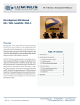
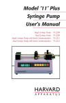
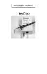
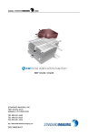
WWW.
.COM
REF 90018
User Manual
STANDARD IMAGING, INC.
3120 Deming Way
Middleton, WI 53562-1461
Sep / 2008 ©2008 Standard Imaging, Inc.
DOC #80556-02
TEL 800.261.4446
TEL 608.831.0025
FAX 608.831.2202
www.standardimaging.com
General Precautions
Warnings and Cautions alert users to dangerous conditions that can
occur if instructions in the manual are not obeyed. Warnings are conditions that can cause injury to the operator, while Cautions can cause
damage to the equipment.
WARNING:
An electrical shock hazard of up to 1000 VDC is possible
whenever the bias voltage is active. Always set the bias
to the 0% or 0 VDC level whenever a device is connected
to or disconnected from the SuperMAX.
WARNING:
The SuperMAX is not intended to be used in flammable
mixture atmospheres. Do not use with flammable anesthetic mixture with air, with oxygen, or nitrous oxide.
CAUTION:
Proper use of this device depends on careful reading of
all instructions and labels.
CAUTION:
Input voltage on triax connector should be no greater
than +5 V or -5 V.
CAUTION:
This device should never be submerged in water or a
solvent to clean, or scrubbed with an abrasive cleaner as
it is not protected against liquid ingress.
CAUTION:
Do not drop or mishandle unit. Calibration factor changes
may result.
CAUTION:
Do not use sharp objects on the touch screen or speaker
holes.
CAUTION:
Do not disassemble unit since it may result in change
of calibration factor. Refer servicing to qualified individuals.
CAUTION:
Damaged or kinked ionization chamber cables or extension cables should not be used.
CAUTION:
Upon power on, allow for proper warm-up.
CAUTION:
Charge measurements made in modes other than those
used by the calibration agency may result in measurement
errors which exceed the calibration uncertainty.
CAUTION:
Temperature/pressure correction is only applied to radiological units. It is not applied to electrical units.
CAUTION:
Proper use of this device requires a current calibration.
Calibrations should be completed every 2 years.
CAUTION:
The SuperMAX should not be connected to an ion or well
chamber which is used in direct contact with a patient.
Table of Contents
PAGE
2 General Precautions
3 About the SuperMAX Electrometer
4 Device Description
5 General Operation
7 Measurement Interface - Introduction
8 Measurement Interface - Basic Functionality
10 Measurement Interface - Advanced Functionality
13 Chamber Library
16 Check Source
18 Preferences
22 Troubleshooting
22 Parts and Accessories List
23 Maintenance
23 Description of Symbols
24 Explanation of Saved File Export
25 Features and Specifications
27 Customer Responsibility
27 Service Policy
27 Warranty
3120 DEMING WAY
MIDDLETON, WI 53562-1461 USA
WWW.STANDARDIMAGING.COM
About the SuperMAX Electrometer
The SuperMAX is a high-end, reference grade 2-channel
electrometer based on MAX 4000 measurement technology,
with added chamber library, voltage requirements, readout
capability (dose & dose rate) and triggered (threshold)
detection. Control of the SuperMAX is handled by a large,
color LCD touchscreen for fast and easy operation, as well
as convenient display of many measurement parameters
simultaneously.
NOTE: This user manual refers to version 1.1 of the
SuperMAX software. Please contact Standard Imaging
about receiving the latest SuperMAX software version or
a user manual for your version. See SuperMAX startup/
splash screen to see your software’s version number.
Certified initial and 2-year calibrations of the SuperMAX may
be provided by an accredited dosimetry calibration laboratory (ADCL).
Device Description
SuperMAX Electrometer Front Panel Description
Device On/Booting Indicator:
Upon plugging the SuperMAX into AC mains power, this green LED will
blink for several moments indicating the device is booting its internal
operating system. The SuperMAX is turned on and ready for operation
when the LED stops blinking and remains a solid green color.
Power/Standby Button:
Pressing this button when the
green LED (Device On/Booting
Indicator) is not lit will start the
SuperMAX interface. Pressing
this button when the green LED
is lit will put the SuperMAX into
standby mode. Full power off
cannot be achieved unless the
SuperMAX is unplugged.
Mains Power Indicator:
This amber LED indicates that the
SuperMAX is plugged in and AC mains
power is present.
Touch Screen and TFT Display:
The touch screen is the primary input device on the SuperMAX. It can be
tapped with the stylus stored on the left side of the device or simply with a
finger tip. Included with the SuperMAX is a pre-installed screen protector to
help reduce screen wear. Replacement screen protectors and/or styli can be
ordered from Standard Imaging.
SuperMAX Electrometer Rear Panel Description
Measurement Channels:
Connect an ion chamber, well chamber
or other compatible measurement device
to either channel.
USB Ports (2):
These ports support the insertion of the supplied
USB flash drive for saving measurement data.
Replacement USB flash drives can be ordered
from Standard Imaging.
Reset Button:
Use the pin-hole reset
button if the SuperMAX
becomes unresponsive
and “locks up” during
operation. Using the
reset button will not
erase the SuperMAX
internal memory.
Speaker Holes (6):
These holes are for the SuperMAX
internal speaker. Prevent any objects
or liquids from entering the holes.
Ethernet Port:
At this time, the ethernet
port is used for Standard
Imaging internal use only.
Power Adapter Input:
Use only with provided
power supply.
Channel
2
0-1000 VDC
350 µA max
Use only with Globtek®,
Inc. power supply model
GTM21089-1509-T3
Reset
USB
Ethernet
RS232
WARNING:
Middleton, WI 53562 USA
www.standardimaging.com
Channel
1
0-1000 VDC
350 µA max
9VDC @ 1.7A
SUPERMAX ELECTROMETER
REF 90018
RS232 Port:
At this time, the
RS232 port is
used for Standard
Imaging internal
use only.
Electric shock hazard. Do not remove casing.
Refer servicing to a qualified individual.
Serial
Number:
General Operation
The following are simplified, generalized instructions for
taking measurements with the SuperMAX electrometer. The
sections in this manual following General Operation give a
much more detailed look at the various functionality of the
SuperMAX.
1. Connect the detachable AC power cord to the provided
Globtek®, Inc. power supply, attach the AC power cord
to a grounded 120 VAC or 220/240 VAC 50/60 Hz power
outlet, and connect the power supply to the SuperMAX
Electrometer power adapter input.
2. With nothing connected to either channel of the SuperMAX, turn the power on and wait for at least the recommended 1 minute for the electrometer to warm-up.
3. The Channel 1 interface will appear after the recommended warm-up period is complete or bypassed. From
here several options within the main menu (top left corner) are accessible. This example will cover operation
remaining in Channel 1 mode, however basic operation
within Channel 2 or Channel 1/2 modes is similar (see
page 7 for detailed use of measurement features).
4. Select the desired Range of Operation, Low or High from
the on-screen pull down menu (see page 8).
5. Press the Zero button to perform the electrometer zero
adjustment (see page 8). This will take approximately 30
seconds to complete.
6. Connect an ionization chamber to the SuperMAX to channel 1 (or channel 2 depending on mode selection) and
select the desired voltage bias from the pull down menu.
Allow at least 10 minutes for the system to stabilize.
NOTE: Depending on the type of measurements performed, leakage currents within the ionization chamber can be a significant portion of the measured data.
Verify the leakage of the ionization chamber is within
the manufacturer’s stated acceptable limits. The system
zero can be adjusted to compensate for leakage currents
of the ionization chamber by pressing the Zero button
after the chamber has been connected and the system
has warmed up. Refer to page 8 for more information on
system zeroing.
7. Press the Zero button to perform the system zero adjustment, but now with the ionization chamber connected
(see page 8). This will take approximately 30 seconds to
complete.
8. Check the system leakage. Take a reading without exposing the chamber to radiation. This reading should be
less than 0.1% of the final signal expected.
9. Measure the atmospheric temperature and pressure.
10. Optionally, a chamber coefficient/system factor can be
automatically applied to the measurement to calculate
dose or dose rate. Check the box labeled “Apply System
Factor” (see page 10), and a prompt appears to select
a chamber from the Chamber Library (see page 13). If
a system factor is not desired, skip to step 12.
If “Apply System Factor” is selected, the following algorithm is used to calculate the dose or dose rate:
Dose or dose rate = PelecNMraw, where:
Pelec = Electrometer calibration factor, entered on the
Calibration Tab within Preferences (see page
21). Note that Pelec should be set at the value of
1.000 if the electrometer and ion chamber are
calibrated as a unit.
N =
Ion chamber calibration coefficient, entered in
the Chamber Library (see page 14)
Mraw = Raw, uncorrected ion chamber reading
NOTE: To select a chamber, it must first be set up within
the Chamber Library (see page 13).
11. If a system factor is applied, the SuperMAX can also
automatically correct radiological measurements for
temperature and pressure. Check the box labeled “Apply
T/P Correction” (see page 10) and the fields below will
become enabled. A keypad will appear to enter both the
appropriate temperature and pressure values.
If “Apply T/P Correction” is selected, the following algorithm is used to calculate the dose or dose rate, and a
blue icon reading ADC (Air Density Corrected) is shown
in the upper left of the screen:
Dose or dose rate = PTPPelecNMraw, where:
PTP = Temperature-Pressure correction factor*
Pelec = Electrometer calibration factor, entered on the
Calibration Tab within Preferences (see page
21). Note that Pelec should be set at the value of
1.000 if the electrometer and ion chamber are
calibrated as a unit.
N = Ion chamber calibration coefficient, entered in
the Chamber Library (see page 14)
Mraw = Raw, uncorrected ion chamber reading
*The following algorithm is used to calculate PTP:
PTP = ((273.15 + T(°C))/295.15) x (760/P(Torr)) for standard conditions of 22°C and 760 Torr
General Operation Continued
Or
PTP = ((273.15 + T(°C))/293.15) x (760/P(Torr)) for standard
conditions of 20°C and 760 Torr
NOTE: Calibration coefficients provided by an ADCL are
corrected to standard temperature and pressure (In the
US, this is 22 °C and 760 Torr), and a correction for air
density via a temperature/pressure correction must be
applied to clinical measurements to obtain the correct
air kerma strength for the source.
NOTE: Temperature/pressure correction is only applied to radiological units. It is not applied to electrical
units.
12. Turn on or insert the radiation source(s) and take at least
three measurements. For further explanation of the Rate
Measurement, Timed, Continuous and Triggered Charge
Collection modes, see page 8.
NOTE: Rate measurements above 500.0 nA (High range)
or 500.0 pA (Low range) will produce X’s in place of measurement values signifying overload has occurred.
13. Analyze the data taking into account the average of the
readings, system leakage, temperature/pressure corrections, calibration factors and any other appropriate
corrections to be made.
13. When measurements are completed, set bias voltage to 0
VDC (see page 8), turn off the SuperMAX and disconnect
the ionization chamber.
14. If desired, disconnect the power supply from the SuperMAX and disconnect the detachable AC power cord from
the power supply.
Measurement Interface - Introduction
After the splash screen, the SuperMAX measurement interface appears and displays Channel 1.
This section of the manual covers operation when using
Channel 1, but operation using Channel 2 or Channels 1/2
Mode is similar with minor exceptions which will be noted in
the following sections.
Shown below is a basic description of the measurement
interface. The screen is broken up into three major sections:
basic functionality, advanced functionality, and the measurement display.
Read the following pages for a description of each
SuperMAX function.
Bias Menu: Select between Bias Entry,
Reverse Polarity, Bias Off, and the last selected
bias, if applicable
Range Menu: Select between
High Range and Low Range
Zero Button
Main Menu: Select
between Channel 1,
Channel 2, Channel 1/2,
Chamber Library (see
page 13), Check Source
(see page 16), and
Preferences (see page 18)
Charge Collection: Menu,
Control and Status Display,
see page 8
Basic Electrometer
Functionality, see page 8
Measurement Display
Add Measurement
Button, see page 11
Advanced Electrometer
Functionality, see page 10
Status Bar
The Channel 2 view is similar to Channel 1, except for
the blue background for easy identification
The Channel 1/2 operation is similar to either single
channel display, but charge collection modes, the File
tab, and the Add button are combined
Measurement Interface - Basic Functionality
Basic Functionality
The commands covered in this section explain how to the
use the SuperMAX as a traditional electrometer to perform
basic Rate and Charge measurements.
Range Menu
Using the previous selected bias option easily facilitates
switching between two voltages for 1/3 or 1/2 bias ratio
measurement.
Below the bias menu, two values are shown. The top value
is the bias selection, while the bottom value in parenthesis
is the actual bias reading. This design allows visibility of the
actual bias as it settles into the desired value. While this settling occurs, the value will show with yellow characters. When
the bias reading has settled within 2% of the bias selection,
the characters will revert back to white characters.
NOTE: When in Channel 1/2 mode, bias can be set independently for each channel.
Zero Button / System Zeroing
Tap on the range menu to reveal two options:
• High Range: 0-500 nA
• Low Range: 0-500 pA
Tap the desired range, and the SuperMAX will automatically
switch range modes.
NOTE: Each range of operation must be zeroed upon
initial use. To perform subsequent zero adjustments,
press the Zero button.
NOTE: When in Channel 1/2 mode, range can be set
independently for each channel.
Bias Menu
Tapping this button performs a SuperMAX zero on the channel being displayed. It is advised to perform a zero when
switching range, and connecting or disconnecting an ion
chamber from the electrometer.
NOTE: The zero button only performs a zero on the
currently viewed channel. For example, pressing zero
when only channel 1 is displayed will not zero channel
2. To perform a zero on both channels simultaneously,
browse to Channel 1/2 from the main menu and press
the zero button.
Charge Collection
Tap on the bias menu to reveal three options:
• Bias Off: Bias is set to 0 V.
• Reverse Polarity: Quickly switch from positive to negative
or negative to positive
• Select Bias: Use the on-screen numeric pad to select
bias in 1 volt increments from ± 100-1000 V. Optionally,
select between three discreet bias settings: ± 150, 300
or 450 V.
If changing the bias from a previously entered voltage, a
fourth option will appear showing a quick selection of that
previous value.
Tap on the charge collection menu to reveal three options:
• Timed Collection: When selected, a numeric keypad
appears and a time value can be entered in 1 second
increments from 1 to 600 seconds. Tap Start to perform
a charge collection for the duration entered. Tap Stop to
end the collection prematurely.
Measurement Interface - Basic Functionality Continued
•
•
Continuous: When selected, 0 sec will be displayed on
the charge collection menu. Tap Start to begin a charge
collection. Tap Stop to end the charge collection after the
desired duration has passed.
Trigger: This mode allows the SuperMAX to automatically
detect the start and stop of a radiation exposure by measuring the current crossing predetermined limit triggers.
When Trigger is selected, tap Start to ready the electrometer for measurement. When signal exceeds the Trigger
Start value (set in Preferences, see page 21), charge
collection will begin. When signal exceeds the Trigger
Stop value (set in Preferences, see page 21), charge
collection will end. Tap Stop to disarm the trigger mode.
NOTE: Trigger mode is only available for Channel
1 (within either Channel 1 or Channel 1/2 modes).
While still taken on Channel 2 when a trigger occurs,
measurements are always triggered off of Channel 1.
As such, Trigger does not appear as an option within
the Channel 2 mode charge collection menu.
When any charge collection is completed, the measured
value is placed in the Add List for future data export. To learn
more about the Add List, see page 11.
NOTE: When in Channel 1/2 mode, charge collection
is synchronized for both channels. However, resulting
measurement values are kept separate. Also, when the
SuperMAX is in Channel 1 or Channel 2 modes (single
channel), charge collection is simultaneously measured
on both channels independent of which channel is displayed.
Measurement Interface - Advanced Functionality
Advanced Functionality
The commands covered in this section explain how to the use
the SuperMAX to apply system factors and temperature/pressure corrections to measurements as well as export collected
data to a USB flash drive.
The Setup, Data, and File tabs located on the bottom of the
measurement screen are explained in this section.
NOTE: There must be a chamber entered into the Chamber Library in order to apply a system factor. For an explanation of the Chamber Library interface, see page 13.
Tap the desired chamber and tap OK to return to the measurement interface. The chamber selected is shown on-screen
along with an additional measurement display. In the following
screen, Dose Rate has been added as a result of the system
factor applied.
When in Channel 1 or Channel 2 mode, only a single Setup
and Data tab appears for the channel currently displayed.
When in Channel 1/2 mode, a unique Setup and Data tab
appear for each channel as shown below. There is only one
File tab, as all measurement data for both channels is exported simultaneously.
Channel 1 or Channel 2 Mode
Channel 1/2 Mode
Setup Tab
Depending on the units selected during the New Chamber
wizard (see page 13), the measurement display will show
either of the following:
Applying a System Factor
Tap Apply System Factor to bring up the Select a Chamber
window.
•
•
Rate, Dose Rate, Charge
Rate, Charge, Dose
These values are calculated and shown in real-time as measurements are performed.
Applying Temperature/Pressure Correction
When a system factor has been applied, the ability to Apply
T/P (Temperature/Pressure) Correction appears within the
setup tab. Tap Apply T/P Correction to enable the values
shown within the blue field.
10
Measurement Interface - Advanced Functionality Continued
The Add List
The Data tab facilitates the creation of a list of measurement
data points which can be exported from the SuperMAX. This
list is called the Add List.
The Add List consists of a table of measurement data containing the time the measurement was completed and the
value, with units, of that measurement. Additionally, the table
contains a Flag column, which allows specific measurement
points to marked or flagged for any reason. To mark a measurement value, tap the check box next to the corresponding
measurement value.
The corrected value is shown in blue text on the measurement
display. A blue icon reading ADC (Air Density Corrected) is
also shown to call attention to this correction.
NOTE: Temperature/pressure correction is only applied to radiological units. It is not applied to electrical
units.
If there is no pre-existing temperature or pressure entry,
the numeric keypad will automatically display for supplying
temperature and pressure values.
To modify an existing value, tap the appropriate number
shown to display a numeric keypad. Enter the current value
and tap OK to proceed.
NOTE: The SuperMAX does not automatically measure
ambient temperature and pressure values nor does it
display a prompt to verify if temperature and pressure
values have changed over a certain period of time, so
ensuring entered values are correct for the entire duration of measurement is recommended. If temperature
or pressure values shift over time, adjust the values as
described above.
Data Tab
The radio-type buttons to the left of the Add List allow browsing of captured measurement data of any type. If no system
factor is applied, only Rate and Charge radio buttons will
be available. When a system factor is applied, Dose Rate
or Dose radio buttons will be also shown depending on the
parameters of the system factor applied.
Adding Measurement Data to the Add List
It is not necessary to use the radio buttons to view the data
type for which data is being added. Rate, dose rate, charge,
and dose measurement values will be added to the appropriate field automatically.
• Adding a Charge or Dose Measurement
Whenever a charge collection (timed, continuous, or
trigger) is completed, the resulting charge and/or dose
measurement value is automatically added to the Add
List.
• Adding a Rate or Dose Rate Measurement
Rate and dose rate are values are added manually with
the Add Measurement button (or Add Button, abbreviated
for space in Channel 1/2 mode) described below.
or
Tapping this button adds the currently displayed rate and/or
dose rate measurement to the Add List.
11
Measurement Interface - Advanced Functionality Continued
NOTE: When in any mode (Channel 1, Channel 2, Channel 1/2), tapping the Add Measurement or Add button
will add rate measurement data to both of the channel
Add Lists.
File Tab
Some USB flash drives may take up to 15 seconds to
register with the SuperMAX software. Ensure the USB
flash drive is connected properly and wait a brief moment before attempting to save again. Also try to unplug
and re-plug the USB flash drive from the SuperMAX. If
the USB flash drive is plugged into the SuperMAX before the device is turned on, it may not be recognized
by the software. If two USB flash drives are attached
to the SuperMAX, only the first drive attached will be
recognized.
Subsequent save operations are performed by tapping the
save button. If the save operation is successful, the star (*)
will disappear from the end of the file name.
The File tab allows for the export of measurement data that
appears on the Add List. Operation is similar to that of popular
word processing programs. Shown on the tab is the name of
the current working file, as well as New and Save buttons. If
the file has not been previously saved, the name “untitled”
appears. A star (*) is shown as a suffix if new data has been
added to the Add List since the last save occurred.
Saving Data
Before attempting to save a file, connect a USB flash drive
to one of the two available USB ports on the SuperMAX. Tap
the Save button to bring up the following prompt.
NOTE: When saving a file, measurement data from both
channels will be saved regardless of which mode (Channel 1, Channel 2, Channel 1/2) the SuperMAX is set to.
For example, if compiling measurement data when in the
Channel 1 mode Add List, this data will still be shown
on the “Data Ch. 1” tab when switching to Channel 1/2
mode.
For an explanation of the exported file format, see page
24.
Starting a New File
To clear the Add List and start a new measurement data file,
tap the New button. If the Add List contains un-saved data,
a prompt will display with the option to save this data before
continuing. A new untitled file will be started with an empty
Add List within the Data tab.
Tap the file name box to bring up an on-screen keypad for
file name entry. Tap in the desired file name and tap OK to
continue. If the save operation was successful, the file name
entered will be displayed on the file tab, and .CSV will be
written to the USB flash drive.
NOTE: The following error may occur:
12
Chamber Library
The Chamber Library allows for adding system factors by
way of chamber calibration data into the SuperMAX interface.
Most types of ionization or well chambers can be used, and
multiple calibrations for individual chambers can be entered
for additional flexibility.
The Chamber Library is accessed through the main menu in
the top left corner of the SuperMAX interface. This section of
the manual covers adding, editing and deleting of chambers
within the interface.
Chamber Selection Table:
Model, Serial Number and Beam/
Isotope are shown with each
column sortable by clicking on
each green heading button
Main Menu:
Select
between
Channel 1,
Channel 2,
Channel 1/2
(see page
7), Chamber
Library, Check
Source (see
page 16), and
Preferences
(see page 18)
Scroll
Buttons
Calibration
Information:
Parameters for the
selected chamber
are displayed here
Status Bar
Chamber Management Buttons:
Create, edit, and delete
chambers and calibrations
Adding a New Chamber
Step 1: Chamber Model and Serial Number
Tap the New Chamber button to begin the New Chamber
Wizard. This wizard will walk through the steps needed to
add a chamber to the Chamber Library.
The first screen prompts for the chamber model and serial
number. Tap each entry box to display a on-screen keypad,
allowing entry. Once the fields have been completed, tap
Next to continue the wizard.
NOTE: Before adding a new chamber, a password must
be entered to help prevent inadvertent changes. This
password is 3120.
13
Chamber Library - Continued
Step 2: Calibration Report Information
Step 3: Chamber Calibration Information
Next, calibration report information is required. Enter the
report name or number listed on the calibration document
along with the date of the report/calibration.
The chamber calibration information is next. Beam/Isotope,
Aion and polarity values have no bearing on the calculated
system factor, and are provided for the convenience of identifying the calibration. However, the calibration coefficient,
units, are needed for the calculation of the system factor.
When entering the report date, the date selection tool shown
below will be displayed.
Once this date is entered, the calibration due date is automatically filled in, with a date two years following the report date.
This value can be changed by clicking on the calibration due
date field, but ionization or well chamber calibration is recommended every two years by the AAPM TG-51 protocol.
NOTE: If a chamber is within 60 days of needing a calibration, an icon (
) will show next to the chamber name on
the main chamber library screen. Additionally, a message
will appear on the SuperMAX splash screen indicating a
calibration may be soon or past due.
Tap Next to continue the wizard.
14
All of these values are entered via
on-screen keypad except for units,
which is selected from a pre-set list
of options via a pull down menu as
shown to the right.
Nsk:µGym2/hA
Verify that the selected default units
match the reported units of the calibration factor and adjust the exponent if needed.
NA:Ci/A
Tap Next to continue the wizard.
Step 4: Review
The next screen will show a summary of all chamber parameters
for review. If necessary, tap Back
to navigate through the wizard and
make any changes, or tap Finish to
register the chamber in the Chamber
Library.
Nsk:Gym2/hA
Nx,sk:Rm2/hA
NA:GBq/A
ND,W:µGy/sec/A
NA:MBq/A
NA:µCi/A
Nk:Gy/C
Nx:R/C
NGas:Gy/C
ND:Gy/C
ND,W:Gy/C
Chamber Library - Continued
At this point, additional options are displayed allowing for return to the Chamber Library, adding another calibration for the
new chamber, or adding another new chamber altogether.
Adding a Calibration to an Existing Chamber
To add a calibration to an existing chamber, select it from
the Chamber Library main screen and tap the Add Calibration button.
NOTE: Before adding a calibration, a password must
be entered to help prevent inadvertent changes. This
password is 3120.
When adding another calibration coefficient for the new chamber, the wizard will return to step 2 with the chamber model
and serial number already completed. Adding another new
chamber will restart with wizard from the beginning.
A wizard identical to the new chamber wizard will appear
beginning at step 2 with the chamber model and serial number already completed. Step through the wizard to create an
additional calibration and once completed, the new calibration
information will be saved to the Chamber Library.
Deleting an Existing Chamber/Calibration
Editing an Existing Chamber/Calibration
To delete a chamber or calibration, select it from the Chamber
Library main screen and tap the Delete Chamber/Calibration
button. A prompt will appear to confirm this operation.
To edit an existing chamber or calibration, select it from the
Chamber Library main screen and tap the Edit Chamber/
Calibration button.
NOTE: Before deleting a chamber or calibration, a
password must be entered to help prevent inadvertent
changes. This password is 3120.
NOTE: Before editing a chamber or calibration, a
password must be entered to help prevent inadvertent
changes. This password is 3120.
Each item in the Chamber Library list is a separate entity,
meaning if multiple calibrations exist for an individual chamber, all calibrations must be deleted separately to completely
remove a chamber from the chamber library.
A wizard identical to the new chamber wizard will appear
with all chamber and calibration parameters filled in. Step
through the wizard editing the desired parameters and once
completed, the chamber and calibration information will be
saved to the Chamber Library.
15
Check Source
Check Source is a simple utility for creating a source database and calculating the projected activity of a radiation
source. This utility is separate from the measurement and
chamber library modes within the SuperMAX.
Main Menu: Select between Channel 1,
Channel 2, Channel 1/2 (see page 7),
Chamber Library (see page 13), Check
Source, and Preferences (see page 18)
Check Source is accessed through the main menu in the top
left corner of the SuperMAX interface. This section of the
manual covers adding, editing and deleting sources as well
as calculating the projected activity of radiation sources.
Scroll
Buttons
Source Details: Selected source
name, serial number, original
measured value, date of original
value are displayed here
Source
Selection
Table:
Source name
and serial
number are
displayed
here
Projected
Activity:
After a date has
been entered, the
projected activity
is displayed
Status Bar
Source Management Buttons:
Create, edit, and delete sources
Adding a New Source
Tap the New Source button to display the Create New Source
form. Complete the fields on this form to add a new source
to the Check Source database.
NOTE: Before adding a new source, a password must
be entered to help prevent inadvertent changes. This
password is 3120.
16
Source Name, HalfLife, Serial Number
and Activity are all
entered via an onscreen keypad while
Units are entered via
a pull-down menu
and On Date is selected via the date
selection tool.
Check Source Continued
Shown below is the list of units available:
Calculating Projected Activity
To calculate a source’s projected activity, select it from the
Check Source main screen. The source parameters are
displayed on the upper right portion of the screen. Tap the
Date button.
The values on this form are the basis for the projected activity
calculation. When completed, tap the OK button and the new
source is added to the Check Source database.
The date selection tool is displayed.
Editing an Existing Source
To edit an existing source, select it from the Check Source
main screen and tap the Edit Source button. Make any desired changes and tap the OK button to save the changes
to the database.
NOTE: Before editing a source, a password must be
entered to help prevent inadvertent changes. This password is 3120.
The activity value can be calculated to either a future or
past date. Enter the desired date and tap the OK button to
continue. The projected activity is shown on the main Check
Source screen.
Deleting an Existing Source
To delete a source, select it from the Check Source main
screen and tap the Delete Source button. A prompt will appear to confirm this operation.
NOTE: Before deleting a source, a password must be
entered to help prevent inadvertent changes. This password is 3120.
NOTE: The calculated activity value is only displayed for
reference and is not saved.
NOTE: The following algorithm is used to calculate the
activity of a check source:
A = Aoe-Lt, where:
A = Activity on chosen date
Ao = The original activity of the check source on the reference date (On Date)
L = (0.693/half-life of the isotope in years)
t = Elapsed time, in years, calculated from the difference
between the reference date (On Date) and the current
or projected date
17
Preferences
To access and change SuperMAX preferences, select Preferences from the main menu. The Preferences section is split
into four main tabs: General, Data Management, Measurement and Calibration. In addition, the SuperMAX software,
firmware and OS build/version numbers can be accessed by
tapping the System Information button.
Once changes are made to any preference, the Apply button
becomes enabled. Tap the Apply button to save any changes
made. If the Apply button is not tapped, a prompt will display
upon leaving the Preferences section to save or discard any
changes made.
Time Format
Select the desired time format by taping the radio button
adjacent to either 12 Hour Format or 24 Hour Format.
Date Format
This section of the manual will explain the preferences settings in each of the four main tabs.
General Preferences
Select the desired date format by tapping the radio button
adjacent to either MM/DD/YYYY (Month/Day/Year) or
DD/MM/YYYY (Day/Month/Year).
Display Brightness
Tap the up and down arrow buttons to adjust the display from
dimmer (lower number) to brighter (higher number).
Setting Date and Time
Sound Volume
Tap the Set Date/Time button to display the date selection
tool. Enter the current date and tap Next. The time selection
tool is displayed. Enter the current time and select finish to
complete the change. The changes made will be displayed
in the status bar along the bottom of the screen.
Tap the up and down arrow buttons to adjust the sound volume from softer (lower number) to louder (higher number).
A sound will play upon each change to signify the new volume level.
18
Preferences Continued
Password Protection
Certain function such as the Chamber Library are password
protected to prevent inadvertent changes. If you wish to turn
off this protection, tap the checkbox adjacent to Password
Protection Enabled.
NOTE: To change this option, a password must be entered. This password is 3120.
Software Update
Before initiating a software update, use a PC to place a new
SuperMAX software update into the root directory of a USB
flash drive.
Insert this flash drive it into one of the two available SuperMAX USB ports.
Some USB flash drives may take up to 15 seconds to
register with the SuperMAX software. Ensure the USB
flash drive is connected properly and wait a brief moment before attempting to perform the update again.
Also try to unplug and re-plug the USB flash drive from
the SuperMAX. If the USB flash drive is plugged into the
SuperMAX before the device is turned on, it may not be
recognized by the software. If two USB flash drives are
attached to the SuperMAX, only the first drive attached
will be recognized.
Upon completion of the this first part of the update, a dialog
box will appear requesting for a cycle of power. Unplug the
SuperMAX from its power adapter and re-plug it back in after
waiting a few seconds.
IMPORTANT: Be certain to unplug the power adapter
and not just turn the power off using the circular power
button on the front of the SuperMAX.
After re-plugging the power adapter, the display will be dark,
but the green LED on the SuperMAX front label will blink
green for up to 20 seconds. This is the SuperMAX software
booting up. After this period, the SuperMAX software will
launch and the update will be complete.
Touch Screen Calibration
Tap the Software Update button to begin the update process.
The following dialog box will display:
To perform a touch screen calibration, tap the Calibrate Touch
Screen button. The calibration utility will be shown. Follow the
instructions on-screen to complete the calibration process.
NOTE: While using the SuperMAX interface does not
require use of a stylus, it is recommended to perform
this process with one for greater precision.
If the update file is found successfully, the SuperMAX software will perform a system update.
NOTE: The following error may occur:
When calibration is completed, tap the screen to save the
new settings or wait as stated on screen to keep the previous values.
19
Preferences Continued
Data Management Preferences
Measurement Preferences
Clear Chamber Library Data
Set Pressure Standard
To clear all Chamber Library data, tap the Clear Chamber
Library Data button. A prompt will appear to confirm this
operation.
NOTE: Before clearing chamber library data, a password
must be entered to help prevent inadvertent changes.
This password is 3120.
Clear Check Source Data
To clear all Check Source data, tap the Clear Check Source
Data button. A prompt will appear to confirm this operation.
NOTE: Before clearing check source data, a password
must be entered to help prevent inadvertent changes.
This password is 3120.
NOTE: Before changing the pressure standard, a
password must be entered to help prevent inadvertent
changes. This password is 3120.
Tap the Pressure Standard pull-down menu to display the
available options. Tap the desired value to select it. Changing the pressure standard will clear the pressure value set
on any measurement screen.
Set Temperature Standard
NOTE: Before changing the temperature standard, a
password must be entered to help prevent inadvertent
changes. This password is 3120.
Tap the Temperature Standard pull-down menu to display the
available options. Tap the desired value to select it. Changing
the temperature standard will clear the temperature value set
on any measurement screen.
20
Preferences Continued
Set Default Charge Collection Type
Calibration Preferences
Select between Timed, Continuous or Triggered Charge Collection modes. This preference will be applied to Channel 1,
2, and Channel 1/2 modes.
Set Trigger Values
Trigger values are adjustable for both the high and low range.
The default settings are Start 4.0 pA and Stop 2.5 pA for high
range, and Start 0.8 pA and Stop 0.5 pA for low range. These
values are adjustable from 0.01 - 9.99 pA. Tap the Start or
Stop value to edit each independently. Trigger values must
be larger than 0.0, and the Start value must be larger than
the Stop value.
NOTE: Before changing trigger values, a password must
be entered to help prevent inadvertent changes. This
password is 3120.
When making measurements in the presence of larger leakage currents, it may be necessary to raise the trigger values.
Conversely, since the start trigger value determines the
minimum dose rate, it may be necessary to lower the trigger
value for other measurements.
NOTE: Charge measurements made in modes other
than those used by the calibration agency may result
in measurement errors which exceed the calibration
uncertainty.
Calibration Last Performed / Calibration Date Due
These values can be entered from a calibration report for
quick reference.
NOTE: If the SuperMAX is within 60 days of needing
a calibration, an icon (
) will show next to the
chamber name on the main chamber library screen.
Additionally, a message will appear on the SuperMAX
splash screen indicating a calibration may be soon or
past due.
NOTE: Before changing these dates, a password must
be entered to help prevent inadvertent changes. This
password is 3120.
Calibration Factors
After the password is entered, the Start and Stop values can
be entered via an on-screen keypad.
Calibration factor values received from a calibration agency
for Channel 1 and 2, high range and low range can be entered
here for added computational convenience.
21
Preferences Continued
Troubleshooting
NOTE: Before changing calibration factors, a password
must be entered to help prevent inadvertent changes.
This password is 3120.
Questionable Readings
If readings are off, determine if there is any leakage from the
SuperMAX or ionization chamber. Follow steps 1 - 7 under
General Operation.
NOTE: These factors are only applied to system factor
corrected measurements, i.e. dose and dose rate. See
page 10 to learn more about applying a system factor.
Electrical measurements, i.e. rate and charge, are always
displayed as raw values and are not affected by these
factors.
The default setting is 1.000 for each calibration factor.
When the values are set to 1.000, essentially no factor
is applied. Tap each value to enter it with the on-screen
keypad.
For reference, the terminology used to develop the nomenclature within the SuperMAX software is based on ICRU
Report No. 76:
Indication (of a measuring instrument) is the value of the
quantity provided by a measuring instrument.
Note: The value read from the displaying device can
be called the direct indication; it is multiplied by the
instrument constant to give the indication. The quantity can be the measurand, a measurement signal, or
another quantity to be used in calculating the value of
the measurand. For a material measure, the indication
is the value assigned to it.
Instrument constant is the coefficient by which the direct
indication of the measuring instrument must be multiplied to
give the value of the measurand, or of a quantity to be used
to calculate the value of the measurand.
Calibration coefficient is the quotient of the conventional
true value of the quantity to be measured and the direct
indication of the instrument normalized to the reference
conditions. The calibration coefficient is equivalent to the
instrument constant multiplied by the calibration factor.
Calibration factor is the factor by which the indication (direct
indication multiplied by the instrument constant), of the device is multiplied to obtain the conventional true value of the
quantity to be measured under reference conditions.
No Response
If the SuperMAX does not respond to any commands from
the touch screen for more than 10 seconds, use the external
reset switch to restart the unit. See page 4 for details.
Electromagnetic or Other Interference
If the SuperMAX causes or is affected by interference with
other equipment, try to correct the interference by performing the following:
-
-
-
Cannot Detect USB Flash Drive
Some USB flash drives may take up to 15 seconds to register
with the SuperMAX software. Ensure the USB flash drive is
connected properly and wait a brief moment before attempting to perform the save or update operation again. Also try to
unplug and re-plug the USB flash drive from the SuperMAX. If
the USB flash drive is plugged into the SuperMAX before the
device is turned on, it may not be recognized by the software.
If two USB flash drives are attached to the SuperMAX, only
the first drive attached will be recognized.
If you require further assistance, please contact Standard
Imaging’s Service Department at (800) 261-4446 or (608)
831-0025 for international calls. A list of frequently asked
questions (FAQs) can be found on our website:
www.standardimaging.com
Parts and Accessories List
REF
Description
90018
80556
72731
72730
72250
72245
SuperMAX Electrometer
SuperMAX User Manual
SuperMAX Power Supply
Optional International Power Cord Set
Optional SuperMAX Carrying Case
Optional SuperMAX Accessory Kit (includes
extra stylus, extra USB flash drive, and 5 extra
screen protectors)
Stylus
USB Flash Drive
LCD Touchscreen Protector, set of 5
11426
11444
11443
22
Increase separation between equipment
Connect the power supply power cord into a different
grounded AC outlet or into a circuit controlled by a
different circuit breaker.
Consult Standard Imaging, Inc.
Maintenance
As is standard practice for other electrometers, it is recommended that the SuperMAX be calibrated every 2 years. This
calibration should be performed by an accredited dosimetry
calibration laboratory (ADCL).
Exterior cleaning of the device can be done with a soft brush
and a cloth. Gently brush all surfaces to remove dirt and
dust. Remove any remaining dirt with a cloth slightly dampened with a solution of mild detergent and water or a liquid
disinfecting agent. Do not use water or liquid on triax jacks.
Do not permit any liquid to seep into the SuperMAX in any
manner during cleaning. It is not recommended to clean the
window of the LCD with anything other than a mild detergent
and a very soft cloth. Failure to use a soft cloth may result in
a scratched display, and this may impair the visibility of the
LCD. Included with the SuperMAX is a pre-installed screen
protector to help reduce screen wear. Replacement screen
protectors can be ordered from Standard Imaging.
There are no user serviceable parts in the SuperMAX.
Sterilization of the SuperMAX is not required.
If assistance is desired in the proper disposal of this
product (including accessories and components), after
its useful life, please return to Standard Imaging.
Over the years, Standard Imaging has had product reports
of drift or leakage involving its ion chambers, well chambers
and electrometers. During the investigation and/or servicing
of these products it became apparent a significant portion
of these reports were caused by dirty triax connectors. The
cause is typically dust that has collected on the inside connector.
To minimize these reports and unnecessary service, Standard
Imaging is providing a triax connector cleaning procedure.
This triax connector cleaning procedure should be periodically completed or whenever there are concerns of drift or
leakage. Heavier product use may require more frequent
cleanings.
Prior to cleaning a triax connector, ensure:
• The ion chamber or well chamber is disconnected from
the electrometer.
• There is no water or moisture visible in the triax connector.
To clean a dirty triax connector:
• Remove the connector cap (if applicable).
• Use only a dry and oil free compressed air source, such
as Chemtronics® Ultra Jet.
• Gently blow dirt and contaminants from the inside of the
connector, moving the air source in a circular manner a
few inches from the connector.
After cleaning a dirty triax connector:
• Use the connector cap when not in use (if applicable).
Do not:
• Use sharp objects to attempt to clean a dirty triax connector.
• Use a compressed gas other than air.
• Use a compressed gas source that may have moisture
or oil in the source or lines.
• Use your mouth to blow on the connector.
• Disassemble the connector.
• Touch the internal parts of the connector with your finger.
If this procedure does not resolve the drift or leakage issues,
contact the Customer Service Administrator to coordinate the
return the product to Standard Imaging for further service.
If there are any questions or comments regarding this information, please contact Standard Imaging or your authorized
dealer.
Description of Symbols
The following
symbols are found
on the SuperMAX
Electrometer:
Power On
Power/Standby Button
Attention, Consult
Accompanying Documents
Dangerous Voltage
Present Inside Enclosure
Signal Input
USB Port
Ethernet Port
Reset
23
Explanation of Saved File Export
When exporting data from the SuperMAX, the file type is a
*.CSV file, (comma separated value), that can be directly
opened with any spreadsheet application. The resulting file
will have data labels as described below.
M (13)
Bias (VDC)
Bias setting at time of measurement
N (14)
T/P Correction
(1 or 0) 1 if T/P correction is enabled
at time of measurement, 0 if not
The structure of the file is split into three main sections:
General Electrometer Information, Channel 1 Measurement
Data, and Channel 2 Measurement Data.
O (15)
Temperature
Temperature setting at time of
measurement
P (16)
Pressure
Pressure setting at time of
measurement
General Electrometer Information:
Q (17)
Temperature
Standard
Temperature standard at time of
measurement
R (18)
Pressure
Standard
Pressure standard at time of
measurement
S (19)
Timed
(1 or 0) 1 if measured value is from a
timed charge collection, 0 if not
T (20)
Duration (sec)
Duration of timed charge collection, if
applicable
U (21)
Continuous
(1 or 0) 1 if measured value is from a
continuous charge collection, 0 if not
V (22)
Elapsed (sec)
Duration of continuous charge
collection, if applicable
W (23)
Trigger
(1 or 0) 1 if measured value is from a
triggered charge collection, 0 if not
X (24)
Trigger Start High
High range trigger start value at time
of measurement
Y (25)
Trigger Stop High
High range trigger stop value at time
of measurement
Z (26)
Trigger Start Low
Low range trigger start value at time
of measurement
AA (27)
Trigger Stop Low
Low range trigger stop value at time
of measurement
Column
A (1)
B (2)
C (3)
D (4)
E (5)
F (6)
G (7)
H (8)
Data Label
Description
SuperMAX
Identifies that this data is from the
SuperMAX Electrometer
Serial Number
Last Cal Date
Software Version
Software Build
Firmware Version
OS Version
OS Build
SuperMAX serial number
Date of last SuperMAX calibration
SuperMAX software version number
SuperMAX software build number
SuperMAX firmware version number
SuperMAX OS version number
SuperMAX OS build number
Channel 1 (or Channel 2) Measurement Data:
Column
Data Label
Description
A (1)
Flagged
(1 or 0) 1 is measurement point is
checked in the Add List, 0 if not
AB (28)
Chamber Model
Model of chamber selected at time of
measurement, if applicable
B (2)
Date
Date when measurement was taken,
in the format MM/DD/YYYY
AC (29)
Serial Number
Serial number of chamber selected
at time of measurement, if applicable
C (3)
Time
Time when measurement was taken,
in the format HH:MM:SS
AD (30)
Beam/Isotope
Beam/isotope of chamber selected at
time of measurement, if applicable
D (4)
Rate
Rate value, if applicable
AE (31)
Coefficient
Coefficient of chamber selected at
time of measurement, if applicable
E (5)
Rate Unit
Rate unit of value in previous
column, if applicable
AF (32)
Coefficient Units
Coefficient unit of chamber selected
at time of measurement, if applicable
F (6)
Dose Rate
Dose rate value, if applicable
AG (33)
Report Name
G (7)
Dose Rate Unit
Dose rate unit of value in previous
column, if applicable
Calibration report name of chamber
selected at time of measurement, if
applicable
AH (34)
Report Date
Calibration report date of chamber
selected at time of measurement, if
applicable
AI (35)
Cal Due Date
Calbration due date of chamber
selected at time of measurement, if
applicable
AJ (36)
Aion
Aion value of chamber selected at
time of measurement, if applicable
AK (37)
Polarity (VDC)
Calibration polarity value of chamber
selected at time of measurement, if
applicable
H (8)
Charge
Charge value, if applicable
I (9)
Charge Unit
Charge unit of value in previous
column, if applicable
Dose
Dose value, if applicable
Dose Unit
Dose unit of value in previous
column, if applicable
Range
(high or low) Range setting at time of
measurement
J (10)
K (11)
L (12)
24
Features and Specifications
Rate Mode Ranges:
Charge Mode Ranges:
Low:
0.001 pA – 500.0 pA
0.001 – 0.999 pA
1.000 – 9.999 pA
10.00 – 99.99 pA
100.0 – 500.0 pA
High:
0.001 nA – 500.0 nA
0.001 – 0.999 nA
1.000 – 9.999 nA
10.00 – 99.99 nA
100.0 – 500.0 nA
Low: 0.001 pC – 999.9 µC
0.001 – 9.999 pC
10.00 – 99.99 pC
100.0 – 999.9 pC
1.000 – 9.999 nC
10.00 – 99.99 nC
100.0 – 999.9 nC
1.000 – 9.999 µC
10.00 – 99.99 µC
100.0 – 999.9 µC
High: 0.001 nC - 999.9 µC
0.001 – 9.999 nC
10.00 – 99.99 nC
100.0 – 999.9 nC
1.000 – 9.999 µC
10.00 – 99.99 µC
100.0 – 999.9 µC
Rated Effective Range on Input Currents:
0.400 pA – 500.0 nA (± .25% of minimum effective scale reading)
Range Switching:
User selectable
Display Resolution:
LOW: Rate mode/Charge mode
HIGH: Rate mode/Charge mode
0.001 pA / 0.001 pC
0.001 nA / 0.001 nC
Main Software Functions:
Channel 1 Main Data and Setup
Channel 2 Main Data and Setup
Combined Channels Data and Setup
Chamber Library
Check Source Library
Preferences
Charge Collection Modes:
Manual Start/Stop - User presses Start to begin collection and Stop to end
Timed Mode - Selectable timer from 1 to 600 sec in 1 second increments
Trigger Mode – current exceeding pre-selected trigger values starts and stops collection
Countup/Countdown Resolution:
1 second (count up for Manual Start/Stop Mode, count down for Timed Mode)
Trigger Levels for Charge Collection:
Set trigger start and stop levels via Preferences interface
Repeatability:
± 0.10%
Long Term Stability:
± 0.5% over 1 year
Stabilization Time:
± 0.1% of value at 1 hour for measurements taken at 15 minutes and 6 hours
Non-linearity:
± 0.25%
Zero Drift:
± 0.25%
Zero Shift:
± 0.25%
Response Time:
High range: < 2 s, Low range: 12 s
See www.standardimaging.com for applicable tech notes.
Specifications are subject to change without notice.
25
Features and Specifications Continued
Operating Parameters:
Temperature:
Relative Humidity:
Pressure:
15 to 35 °C
20 to 80% non-condensing
650 to 770 mmHg
Storage Parameters:
Temperature:
Relative Humidity:
Pressure:
-15 to 50 °C
10 to 95% non-condensing
600 to 800 mmHg
Display:
Color LCD TFT touch screen. VGA (640x480) resolution, 6.4” diagonal
Input:
2 channels, BNC 2 lug triax
Bias Voltage:
± VDC for the following: 0 to 1000 VDC in 1 VDC increments, 350 µA max
Zeroing:
Zero via button push - Display indicates zeroing in progress.
Output:
RS232 (internal use only, not currently supported)
(2) USB ports (Input devices only, keyboard or thumb drive – no mouse support)
Ethernet (internal use only, not currently supported)
Chamber library calibration coefficients:
Amps
Amp System factors:
Nsk:µGym2/hA
Nsk:Gym2/hA
Nx,sk:Rm2/hA
NA:GBq/A
NA:Ci/A
ND,W:µGy/sec/A
NA:MBq/A
NA:µCi/A
Coulombs
Coulombs System Factors:
Nk:Gy/C
Nx:R/C
NGas:Gy/C
ND:Gy/C
ND,W:Gy/C
Real-Time Clock:
On board, for data validation and storage
Audio:
On board speaker for audio feedback on start-up, button presses, operator alerts, etc.
Dimensions:
Width:
Height:
Length:
26.7 cm (10.5 in)
8.1 cm (3.2 in)
21.1 cm (8.3 in)
Mode of Operation:
Continuous
Weight:
1.4 kg (3.0 lbs)
Power Requirements:
100-240 VAC, 0.5 A max, 50/60 Hz input to external power supply,
9 VDC, 1.7 A power supply output to electrometer input,
UL/TUV Listed Globtek®, Inc. power supply model GTM21089-1509-T3
The use of any power supply other than this UL/TUV recognized power supply GlobTek®, Inc.
Model GTM21089-1509-T3 and using alternates other than the UL/CSA recognized power cord can
degrade minimum safety. The proper replacements from Standard Imaging, Inc. are required for
compliance with the requirements of IEC 60601-1.
Product Standards:
IEC 60601-11, IEC 60601-1-21, IEC 60601-1-42, IEC 607312
-
-
-
Shock Classifications:
1
Externally Certified; Designed to Meet
2
26
Authorized representative for the EU is AMA, Ltd., St. Felix House, Flitcham, King’s Lynn, Norfolk, United Kingdom, PE31 6BU.
Competent Authority for the EU is the Medical Products Agency, Sweden.
Notified Body for the EU is Semko, Sweden.
Class I - External Power Supply
Class II - Electrometer
See www.standardimaging.com for applicable tech notes.
Specifications are subject to change without notice.
Customer Responsibility
Warranty
This product and its components will perform properly and reliably only when
operated and maintained in accordance with the instructions contained in
this manual and accompanying labels. A defective device should not be
used. Parts which may be broken or missing or are clearly worn, distorted
or contaminated should be replaced immediately with genuine replacement
parts manufactured by or made available from Standard Imaging, Inc.
Standard Imaging, Inc. sells this product under the warranty herein
set forth. The warranty is extended only to the buyer purchasing the
product directly from Standard Imaging, Inc. or as a new product
from an authorized dealer or distributor of Standard Imaging, Inc.
CAUTION: Federal law in the U.S.A. and Canadian law restrict the
sale, distribution, or use of this product to, by, or on the order of
a licensed medical practitioner. The use of this product should
be restricted to the supervision of a qualified medical physicist.
Measurement of high activity radioactive sources is potentially
hazardous and should be performed by qualified personnel.
Should repair or replacement of this product become necessary after the
warranty period, the customer should seek advice from Standard Imaging
Inc. prior to such repair or replacement. If this product is in need of repair,
it should not be used until all repairs have been made and the product is
functioning properly and ready for use. After repair, the product may need
to be calibrated. The owner of this product has sole responsibility for any
malfunction resulting from abuse, improper use or maintenance, or repair
by anyone other than Standard Imaging, Inc.
The information in this manual is subject to change without notice. No part
of this manual may be copied or reproduced in any form or by any means
without prior written consent of Standard Imaging, Inc.
Service Policy
If service, including recalibration, is required, please contact Standard
Imaging’s Customer Service department by phone or email prior to shipping
the product. Standard Imaging’s Customer Service and Technical Service
staff will attempt to address the product issue via phone or email. If unable
to address the issue, a return material authorization (RMA) number will be
issued. With the RMA number, the product can be returned to Standard
Imaging. It is the responsibility of the customer to properly package, insure
and ship the product, with the RMA number clearly identified on the outside
of the package. The customer must immediately file a claim with their carrier
for any shipping damage or lost shipments. Return shipping and insurance
is to be pre-paid or billed to the customer, and the customer may request a
specific shipper. Items found to be out of warranty are subject to a minimum
service fee of 1 hour labor (excluding recalibrations) for diagnostic efforts
and require a purchase order (PO) before service is performed. With concurrence from customer, the product may be replaced if it is unserviceable or if
the required service is cost prohibitive. Products incurring service charges
may be held for payment. Standard Imaging does not provide loaner products. See the Standard Imaging Warranty and Customer Responsibility for
additional information.
Serialization Information
Standard Imaging products that are serialized contain coded logic in the serial number
which indicates the product, day and year of
manufacture, and a sequential unit number
for identification:
A YY DDD X
A
YY
Unique product ID
Last two digits of the year
(e.g. 1999 = 99, 2000 = 00)
DDD Day of the year (1< DDD < 365)
X
Unique unit ID Number (1 < X < 9)
For a period provided in the table below from the date of original
delivery to the purchaser or a distributor, this Standard Imaging, Inc.
product, provided in the table is warranted against functional defects in
design, materials and workmanship, provided it is properly operated
under conditions of normal use, and that repairs and replacements
are made in accordance herewith. The foregoing warranty shall not
apply to normal wear and tear, or if the product has been altered,
disassembled or repaired other than by Standard Imaging, Inc. or if the
product has been subject to abuse, misuse, negligence or accident.
Product
Standard Imaging Ionization Chambers
Standard Imaging Well Chambers
Standard Imaging Electrometers
Standard Imaging BeamChecker
Products
Standard Imaging Software Products
All Other Standard Imaging Products
Standard Imaging Custom Products
Standard Imaging Remanufactured
Products
Standard Imaging Custom Select
Products
Consumables
Serviced Product
Resale Products
ADCL Product Calibration
(Standard Imaging uses the UWADCL for
recalibrations required under warranty)
Warranty Period
2 years
2 years
2 years
2 years
1 year
1 year
1 year
180 days
90 days
90 days
90 days
As defined by the Original Equipment
Manufacturer
0 - 90 days = 100% of ADCL Calibration Costs
91 - 182 days = 75% of ADCL Calibration Costs
183 – 365 days = 50% of ADCL Calibration Costs
366 – 639 days = 25% of ADCL Calibration Costs
(days from date of shipment to customer)
Standard Imaging’s sole and exclusive obligation and the purchaser’s
sole and exclusive remedy under the above warranties are, at Standard
Imaging’s option, limited to repairing, replacing free of charge or revising
labeling and manual content on, a product: (1) which contains a defect
covered by the above warranties; (2) which are reported to Standard
Imaging, Inc. not later than seven (7) days after the expiration date of the
warranty period in the table; (3) which are returned to Standard Imaging,
Inc. promptly after discovery of the defect; and (4) which are found to be
defective upon examination by Standard Imaging Inc. Transportation related
charges, (including, but not limited to shipping, customs, tariffs, taxes,
and brokerage fees) to Standard Imaging are the buyer’s responsibility.
This warranty extends to every part of the product except consumables
(fuses, batteries, or glass breakage). Standard Imaging, Inc. shall not be
otherwise liable for any damages, including but not limited to, incidental
damages, consequential damages, or special damages. Repaired or
replaced products are warranted for the balance of the original warranty
period, or at least 90 days.
This warranty is in lieu of all other warranties, express or implied,
whether statutory or otherwise, including any implied warranty of
fitness for a particular purpose. In no event shall Standard Imaging,
Inc. be liable for any incidental or consequential damages resulting
from the use, misuse or abuse of the product or caused by any defect,
failure or malfunction of the product, whether a claim of such damages
is based upon the warranty, contract, negligence, or otherwise.
This warranty represents the current standard warranty of Standard
Imaging, Inc. Please refer to the labeling or instruction manual of your
Standard Imaging, Inc. product or the Standard Imaging, Inc. web page for
any warranty conditions unique to the product.
27