1
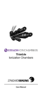
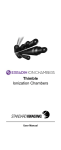
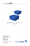
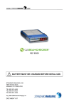
Exradin D1H Diode
Exradin D1V Diode
User Manual
WWW.
.COM
Exradin D1H Diode
Exradin D1V Diode
STANDARD IMAGING INC.
3120 Deming Way
Middleton, WI 53562-1461
Sep / 2012 ©2012 Standard Imaging Inc.
DOC #80655-00
TEL 800.261.4446
TEL 608.831.0025
FAX 608.831.2202
General Precautions
Warnings and Cautions alert users to dangerous conditions that can occur if instructions in the manual are
not obeyed. Warnings are conditions that can cause
injury to the operator, while Cautions can cause damage to the equipment.
WARNING: Proper use of this device depends on
careful reading of all instructions and labels.
WARNING: This diode is intended for quality
assurance measurements. It is not intended to
be connected to a patient for real-time dosimetry
measurements.
CAUTION: Do not apply bias voltage to the diode
at any time. Presence of voltage will damage the
detector.
CAUTION: Do not drop, mishandle, or disassemble
unit since it may result in a change of signal output
or damage to diode. Refer all servicing to qualified
individuals.
CAUTION: Do not sharply bend triaxial cable.
Damage to the cable may result in high leakage
currents.
CAUTION: Connector end of diode detector
should not be submerged in water.
NOTE: Standard Imaging does not assume any
liability or guarantees when the detector is used
with any electrometer or accessories other than
those manufactured by Standard Imaging or
expressly specified to be suitable for use with this
specific type of detector. To maintain full warranty
and product liability rights, always use Standard
Imaging detectors together with Standard Imaging
electrometers.
i
Table of Contents
PAGE
i General Precautions
1Overview
2 General Operation
4Maintenance
5 Parts and Accessories
7 Features and Specifications
10 Service Policy
10 Return Policy
11 Customer Responsibility
12Warranty
3120 Deming Way
MIDDLETON, WI 53562-1461 USA
WWW.STANDARDIMAGING.COM
Overview
The Exradin D1H and D1V Diodes are P-type silicon
diodes attached to a 1.5 m length of low-noise flexible
triaxial cable that is terminated by a BNC type triaxial
connector.
The horizontal design of the D1H allows it to be used in an
orientation similar to that of a small volume ion chamber.
The flat top and bottom surfaces make the D1H ideal for
use with solid water slabs or other phantoms. The internal
diode itself has a circular active area of 1.0 mm2
Top
1
Overview Continued
The D1V Diode uses the same detector as the D1H, but
provides a vertical orientation preferred for water phantom
scanning applications. The D1V is also intended for use
with the LUCY 3D QA Phantom. When positioned with the
circular top facing the radiation source, the circular active
area of 1.0 mm2 faces the beam.
Top
As is standard practice for other diodes, it is
recommended that the Exradin D1H and D1V Diodes
be compared regularly to a known calibrated standard
under controlled radiation conditions for accurate relative
comparison. Prior to shipment, each diode is verified
for radiation performance by comparison to a Standard
Imaging Exradin Ion Chamber.
General Operation
1. With nothing connected to the input jack of the
electrometer, turn the power on and wait at least 15
minutes for warm up.
2. Verify the leakage of the electrometer is within the
manufacturer’s stated acceptable limits.
3. Setup the D1H or D1V Diode for measurement in
a stand, plastic phantom or water phantom. When
positioning, ensure that the active area faces the
beam.
D1H: The three vertical lines on the sides of the
D12H diode provide references to indicate the center
of the active area.
D1V: The laser alignment line around the
circumference of the D1V diode indicates the
position of the active area.
NOTE: While the D1H and D1V are inherently
waterproof without the assistance of sleeves, caps or
other devices, the connector end of the diode should
never be submerged in water.
2
General Operation Continued
4. Connect the diode to the electrometer using an
extension cable if necessary, being certain there is
no bias voltage selected on the electrometer.
5. Allow the electrometer and diode system at least 10
minutes to stabilize, making certain that all cabling is
lying flat and unkinked.
6. Verify the leakages of diode and extension cable
(if used) are within the manufacturer’s stated
acceptable limits. If measured in the presence of
background sources, note that this signal will add to
the leakage of the diode.
7. Some electrometers, such as the Standard Imaging
MAX 4000 and SuperMAX electrometers, allow
the user to zero the device at any time. If desired,
perform this system zeroing now.
8. Check the system leakage. Take a reading without
exposing the diode to radiation. This reading should
be less than 0.1% of the final signal expected. If it
is not, the leakage should be subtracted from the
signal.
9. Irradiate the diode and take at least 3
measurements. Generally, the measurements
should not be moving in only one direction (i.e. three
readings that continue to drop and hence may not
yet be stabilized). If a current measurement is done,
allow sufficient time for value to stabilize.
10. Analyze the data, taking into account the average
of the readings, system leakage, electrometer
calibration, and any other appropriate corrections to
be made.
11. When all measurements are completed, turn off the
electrometer and disconnect the diode.
3
Maintenance
There are no user-serviceable parts within the Exradin
D1H or D1V Diodes. Under no circumstance should the
user attempt to repair or disassemble the diode and/or
connector, as the warranty will become void. Under normal
use, the diode should provide years of trouble-free service.
If assistance is desired in the proper disposal or
recycling of this product (including accessories
and components), after its useful life, please
return to Standard Imaging.
Cleaning Triax Connectors on Ion Chambers
and Extension Cables
Over the years, Standard Imaging has had product
reports of drift or leakage involving its detectors. During
the investigation and/or servicing of these products it
became apparent a significant portion of these reports
were caused by dirty triax connectors. The cause is
typically dust that has collected on the inside connector.
To minimize these reports and unnecessary service,
Standard Imaging is providing a triax connector cleaning
procedure. This triax connector cleaning procedure should
be periodically completed or whenever there are concerns
of drift or leakage. Heavier product use may require more
frequent cleanings.
Prior to cleaning a triax connector, ensure:
•
The detector is disconnected from the electrometer.
•
There is no water or moisture visible in the triax
connector.
To clean a dirty triax connector:
•
Remove the connector cap (if applicable).
•
Use only a dry and oil free compressed air source,
such as Chemtronics® Ultra Jet.
•
Gently blow dirt and contaminants from the inside
of the connector, moving the air source in a circular
manner a few inches from the connector.
After cleaning a dirty triax connector:
•
4
Use the connector cap when not in use (if applicable).
Maintenance Continued
Do not:
•
Use sharp objects to attempt to clean a dirty triax
connector.
•
Use a compressed gas other than air.
•
Use a compressed gas source that may have
moisture or oil in the source or lines.
•
Use your mouth to blow on the connector.
•
Disassemble the connector.
•
Touch the internal parts of the connector with your
finger.
If this procedure does not resolve the drift or leakage
issues, contact the Customer Service Administrator to
coordinate the return the product to Standard Imaging for
further service. If there are any questions or comments
regarding this information, please contact Standard
Imaging or your authorized dealer.
Parts and Accessories
REFDescription
92740
Exradin D1V Diode Detector, Ø 1mm,
(vertical version)
92741
Exradin D1H Diode Detector, Ø 1mm,
(horizontal version)
80441
Exradin Diode Detector User Manual
72193
In-Air Comparison Jig
90015
MAX 4000 Electrometer
90018
SuperMAX Electrometer
5
Performance Graphs
1.30
1.25
1.000
Relative signal
Response ( %)
1.20
Exradin D1V Diode
PTW 60012
Exradin A1SL Ion Chamber
0.950
1.15
1.10
1.05
1.00
0.95
0.90
0.85
0.900
o
0
1.050
1.300
120
5
10
15
20
25
30
Gantry Rotation (degrees)
35
40
0.80
45
Angular Dependence Comparison
Lucy
3D
QA
Phantom,
10x10
cm field, 60Co
Field
Size
Dependence
Comparison
Percent
Depth
Dose
in Water
Comparison
60
Detector
depth
=
10
cm,
6 MV Photons, Varian Clinac 21Co
EX
1.30
1.25
1.250
100
1.200
Response ( %)
Relative signal
Response
( %)
Varian Golden Beam Data
Exradin D1V diode
1.050
60
1.000
0.950
40
0.950
45
0.900
20
0.850
0.900
0.800
0
00 0
120
Exradin D1V Diode
PTW Exradin
60012 D1V diode
Exradin
Ion Chamber
Exradin
A1SL A1SL
Ion Chamber
52
4
510
615 10820 10 25 15
12 3014 3520
16
Gantry
Rotation
(degrees)
Side
length
of square
field (cm)
Depth
(cm)
40
18
45
20
25
Percent Depth Dose in Water Comparison
6 MV Photons, Varian Clinac 21 EX
Response ( %)
80
Varian Golden Beam Data
Exradin D1V diode
60
40
20
0
0
25
6
1.15
1.10
1.05
1.00
0.95
0.90
0.85
100
m Data
Relative signal
1.20
1.000
1.150
80
1.100
mber
40
Angular Dependence Comparison
Lucy 3D QA Phantom, 10x10 cm field, 60Co
1.050
5
10
15
Depth (cm)
20
25
0.80
Features and Specifications
Diode Type:
P-type Si diode
Materials:
C552 shell for EMI shielding and durability, potted with
near-water equivalent epoxy to eliminate air gaps
Outside Diameter:
D1V (REF 92740): Ø 6.88 mm (0.271”) x 46.2 mm
(1.817”) long,
D1H (REF 92741):
6.88 mm (0.271”) x 6.88 mm (0.271”) x 34.8 mm (1.37”)
Diameter of Sensitive Area:
1 mm2 x ~0.05 mm thick
Effective Depth Below Surface:
0.8 mm - Indicator marks or lines clearly identify internal
diode orientation and active face
Intended Energy Range:
Photons: 60Co to 25 MV
Low-Noise Triaxial Cable:
50 ohms, 29 pF/ft, 1.5 m long
Connector availability:
Standard BNC triax, with HV bias capability disabled.
Other connector options such as TNC or type M may be
available upon request
Waterproof:
Yes, may be used in water phantoms, designed to mount
cleanly and easily to available chamber holders
Operating Voltage:
0 VDC bias (protected from accidental high voltage
application)
Signal Polarity:
Positive
Radiation response, typ:
~5 nC/Gy
Leakage current, typ:
<100 fA (typical, depends on electrometer used)
Temperature dependence, typ:
<0.4 % / °C
Sensitivity decrease (at 6 MV):
<1.0 % per kGy
Dose to pulse dependency):
> 99.5% over relevant clinical range.
Dose linearity:
> 99.9%
7
Features and Specifications Cont'd
Field size dependency: > 97.0%
Intended Field size for use:
up to (20 x 20) cm2
Directional Dependence:
< ± 0.5% tilting ± 20
Operating Parameters:
Temperature: 15 to 35 °C
Relative Humidity:
20 to 80% non-condensing
Pressure:
650 to 770 mmHg
Storage Parameters:
Temperature:
-15 to 50 °C
Relative Humidity:
10 to 95% non-condensing
Pressure:
600 to 800 mmHg
Product Standards Compliance:
IEC 60601-11, IEC 607311, WEEE, RoHS
-
Authorized representative for the EU is AMA, Ltd.,
St. Felix House, Flitcham, King’s Lynn, Norfolk,
United Kingdom, PE31 6BU.
-
Competent Authority for the EU is the Medical
Products Agency, Sweden.
-
Notified Body for the EU is Semko, Sweden.
Designed to Meet
1
8
Notes
9
Service Policy
If service, including recalibration, is required, please contact
Standard Imaging’s Customer Service department by phone or
email prior to shipping the product. Standard Imaging’s Customer
Service and Technical Service staff will attempt to address the
product issue via phone or email. If unable to address the issue,
a return material authorization (RMA) number will be issued.
With the RMA number, the product can be returned to Standard
Imaging. It is the responsibility of the customer to properly
package, insure and ship the product, with the RMA number
clearly identified on the outside of the package. The customer
must immediately file a claim with their carrier for any shipping
damage or lost shipments. Return shipping and insurance is
to be pre-paid or billed to the customer, and the customer may
request a specific shipper. Items found to be out of warranty
are subject to a minimum service fee of 1 hour labor (excluding
recalibrations) for diagnostic efforts and require a purchase
order (PO) before service is performed. With concurrence from
customer, the product may be replaced if it is unserviceable or if
the required service is cost prohibitive. Products incurring service
charges may be held for payment. Standard Imaging does not
provide loaner products. See the Standard Imaging Warranty
and Customer Responsibility for additional information.
Return Policy
No merchandise will be accepted for credit without prior approval
of return. Please contact Standard Imaging’s Customer Service
Department to receive a return authorization number before
returning any merchandise for exchange or credit. Products
manufactured by Standard Imaging must be returned within thirty
days of receipt of order in ‘like new’ condition. No credit will be
given for products returned after thirty days from receipt of order.
A minimum twenty percent restocking fee will be charged on all
returned merchandise. All materials returned must be shipped
pre-paid. Credit for returned goods will be issued to customer's
account for use against future purchases of merchandise only.
Special orders, custom products, re-sale (not manufactured by
Standard Imaging) products, and ADCL calibrations will not be
accepted for return credit or exchange.
Serialization Information
Standard Imaging products that are serialized contain coded logic in the serial number
which indicates the product, day and year of
manufacture, and a sequential unit number
for identification:
A YY DDD X
A
YY
Unique product ID
Last two digits of the year
(e.g. 1999 = 99, 2000 = 00)
DDD Day of the year (1< DDD < 365)
X
Unique unit ID Number (1 < X < 9)
10
Customer Responsibility
This product and its components will perform properly and
reliably only when operated and maintained in accordance with
the instructions contained in this manual and accompanying
labels. A defective device should not be used. Parts which
may be broken or missing or are clearly worn, distorted or
contaminated should be replaced immediately with genuine
replacement parts manufactured by or made available from
Standard Imaging Inc.
CAUTION: Federal law in the U.S.A. and Canadian
law restrict the sale, distribution, or use of this
product to, by, or on the order of a licensed medical
practitioner. The use of this product should be
restricted to the supervision of a qualified medical
physicist. Measurement of high activity radioactive
sources is potentially hazardous and should be
performed by qualified personnel.
CAUTION: As desired by IAEA, English is the
default language for labeling and manuals. If
translated versions are available, resolve any
differences in favor of the English versions.
WARNING: Proper use of this device depends on
careful reading of all instructions and labels.
WARNING: Where applicable, Standard Imaging
products are designed to be used with the
versions of common radiation delivery devices,
treatment planning systems and other products
or systems used in the delivery of ionizing
radiation, available at the time the Standard
Imaging product is released. Standard Imaging
does not assume responsibility, liability and/or
warrant against, problems with the use, reliability,
safety or effectiveness that arise due to the
evolution, updates or changes to these products
or systems in the future. It is the responsibility of
the customer or user to determine if the Standard
Imaging product can be properly used with these
products or systems.
Should repair or replacement of this product become
necessary after the warranty period, the customer should
seek advice from Standard Imaging Inc. prior to such repair or
replacement. If this product is in need of repair, it should not
be used until all repairs have been made and the product is
functioning properly and ready for use. After repair, the product
may need to be calibrated. The owner of this product has
sole responsibility for any malfunction resulting from abuse,
improper use or maintenance, or repair by anyone other than
Standard Imaging Inc.
The information in this manual is subject to change without
notice. No part of this manual may be copied or reproduced
in any form or by any means without prior written consent of
Standard Imaging Inc.
11
Warranty
Standard Imaging, Inc. sells this product under the warranty herein set forth.
The warranty is extended only to the buyer purchasing the product directly from
Standard Imaging, Inc. or as a new product from an authorized dealer or distributor
of Standard Imaging, Inc.
For a period provided in the table below from the date of original delivery to the
purchaser or a distributor, this Standard Imaging, Inc. product, provided in the table
is warranted against functional defects in design, materials and workmanship,
provided it is properly operated under conditions of normal use, and that repairs
and replacements are made in accordance herewith. The foregoing warranty shall
not apply to normal wear and tear, or if the product has been altered, disassembled
or repaired other than by Standard Imaging, Inc. or if the product has been subject
to abuse, misuse, negligence or accident.
Product
Warranty Period
Standard Imaging
Ionization Chambers
2 years
Standard Imaging
Well Chambers
2 years
Standard Imaging Electrometers
5 years
Standard Imaging
BeamChecker Products
2 years
Standard Imaging
Software Products
1 year
All Other Standard
Imaging Products
1 year
Standard Imaging
Custom Products
1 year
Standard Imaging
Remanufactured Products
180 days
Standard Imaging
Custom Select Products
90 days
Consumables
90 days
Serviced Product
90 days
Resale Products
As defined by the Original Equipment Manufacturer
ADCL Product Calibration
(Standard Imaging uses the
UW-ADCL for recalibrations
required under warranty, unless
otherwise requested)
0 - 90 days = 100% of ADCL Calibration Costs
91 - 182 days = 75% of ADCL Calibration Costs
183 – 365 days = 50% of ADCL Calibration Costs
366 – 639 days = 25% of ADCL Calibration Costs
(days from date of shipment to customer)
Standard Imaging’s sole and exclusive obligation and the purchaser’s sole and
exclusive remedy under the above warranties are, at Standard Imaging’s option,
limited to repairing, replacing free of charge or revising labeling and manual content
on, a product: (1) which contains a defect covered by the above warranties; (2)
which are reported to Standard Imaging, Inc. not later than seven (7) days after
the expiration date of the warranty period in the table; (3) which are returned to
Standard Imaging, Inc. promptly after discovery of the defect; and (4) which are
found to be defective upon examination by Standard Imaging Inc. Transportation
related charges, (including, but not limited to shipping, customs, tariffs, taxes, and
brokerage fees) to Standard Imaging are the buyer’s responsibility. This warranty
extends to every part of the product excluding consumables (fuses, batteries,
or glass breakage) or material reactions. Standard Imaging, Inc. shall not be
otherwise liable for any damages, including but not limited to, incidental damages,
consequential damages, or special damages. Repaired or replaced products are
warranted for the balance of the original warranty period, or at least 90 days.
This warranty is in lieu of all other warranties, express or implied, whether statutory
or otherwise, including any implied warranty of fitness for a particular purpose. In
no event shall Standard Imaging, Inc. be liable for any incidental or consequential
damages resulting from the use, misuse or abuse of the product or caused by any
defect, failure, malfunction or material reactions of the product, whether a claim
of such damages is based upon the warranty, contract, negligence, or otherwise.
This warranty represents the current standard warranty of Standard Imaging,
Inc. Please refer to the labeling or instruction manual of your Standard Imaging,
Inc. product or the Standard Imaging, Inc. web page for any warranty conditions
unique to the product.