1
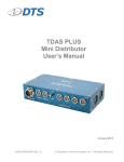
Crash Battery User’s Manual March 2014 10400-00160-MAN (Rev. 0) © Diversified Technical Systems, Inc. - All Rights Reserved Crash Battery User’s Manual March 2014 Table of Contents DTS Support ....................................................................................................................... 3 Introducing the Crash Battery ........................................................................................... 4 Crash Battery Control Panel ............................................................................................. 4 LED Indicators ................................................................................................................. 5 15V IN Power Input Connector ........................................................................................ 6 On/Off Power Switch ........................................................................................................ 6 Power Out Connectors ..................................................................................................... 6 SLICE Connector ............................................................................................................. 7 TDAS Connector .............................................................................................................. 7 Basic Care and Handling ................................................................................................... 7 Shock Rating.................................................................................................................... 7 Mounting Considerations ............................................................................................. 8 Thermal Considerations ................................................................................................... 8 Safety ............................................................................................................................... 8 Communication Features .................................................................................................. 8 Power Management............................................................................................................ 8 Maximum Power Consumption ........................................................................................ 9 Maximum Input Power ..................................................................................................... 9 Input Power Calculations ............................................................................................. 9 Maximum Output Power .................................................................................................. 9 Internal Battery................................................................................................................. 9 Battery Capacity ........................................................................................................ 10 Battery Life Cycle....................................................................................................... 10 Charging/Powering TDAS and SLICE Equipment via the Crash Battery ....................... 10 Power Requirements of TDAS and SLICE Equipment .............................................. 10 Grounding ......................................................................................................................... 11 Troubleshooting Basics .................................................................................................. 12 Appendix A: Connector Information.............................................................................. 13 Suggested Connector Sources ...................................................................................... 14 Appendix B: Mechanical Specifications........................................................................ 15 Appendix C: Safety Data Sheet ...................................................................................... 16 [email protected] ii 10400-00160-MAN (Rev. 0) Crash Battery User’s Manual March 2014 DTS Support TDAS systems are designed to be reliable and simple to operate. Should you need assistance, DTS has support engineers worldwide with extensive product knowledge and crash test experience to help via telephone, e-mail or on-site visits. The best way to contact a DTS support engineer is to e-mail [email protected]. Your e-mail is immediately forwarded to all DTS support engineers worldwide and is typically the fastest way to get a response, particularly if you need assistance outside of normal business hours. All DTS software installs user manuals to support a variety of products; these are available from the Help menu. Additional self-help resources and technical support material can be found at www.dtsweb.com. This manual supports the following products: 10400-00160: Crash Battery [email protected] 3 10400-00160-MAN (Rev. 0) Crash Battery User’s Manual March 2014 Introducing the Crash Battery Supplying primary or back-up power, the Crash Battery seamlessly integrates with all TDAS PRO, TDAS G5 and SLICE data acquisition products. The Crash Battery is a crashworthy power source in a rugged, compact enclosure suitable for use in a wide variety of test environments. Built and tested for 100 g dynamic testing environments. Provides primary power for up to 1 hour at maximum discharge. DTS standard DC power input connector supports an input range of 9-16 VDC (15 VDC nominal). 9 power outputs each provide 10.8 VDC nominal (battery as primary power) or 15 VDC nominal (voltage equal to input) when connected to external power. Supports TDAS and SLICE status (fault) signals. Power and battery status LED indicators. Over- and undervoltage protection, overcurrent protection, power input polarity protection. Integral threaded mounting holes. Crash Battery Control Panel All connectors and LED indicators are accessible from the front panel. See Appendix A for connector information and pin assignments. Crash Battery Control Panel [email protected] 4 10400-00160-MAN (Rev. 0) Crash Battery User’s Manual March 2014 LED Indicators There are two LED indicators that provide Crash Battery status: the ON LED and battery status LED array. The LEDs are an indicator of Crash Battery status only; they do not indicate the status of any attached equipment. A thorough understanding of the LED states will facilitate an efficient approach to troubleshooting and a quick resolution to any problems. Additional troubleshooting information begins on page 12. Unit Off Unit On Unit off (no input power; no output power) Input power applied (input range OK); main output power active Initiation sequence* Unit on (input range OK); all power outputs active Fault Input voltage out of range; output power off – or – Output power overcurrent; output power off – or – Battery capacity <5%; shutdown imminent** * Battery LED initiation sequence follows ON LED initiation sequence. ** Fault condition Unit Off/On; External Power Applied Unit Off*/On; External Power Removed … Charging; number of LEDs = battery capacity number of LEDs = battery capacity Battery Capacity 76 - 100% 51 - 75% 26 - 50% 0 - 25% all LEDs green when fully charged = 0-25% battery low * Press and hold ON switch for >500 msec, <2 sec (LEDs visible for 5 sec) WARNING: Do not perform any critical tests when the battery status LED indicator is blinking green (battery low). [email protected] 5 10400-00160-MAN (Rev. 0) Crash Battery User’s Manual March 2014 15V IN Power Input Connector This connector supports primary power input. The Crash Battery may be charged alone or it can be used to charge all connected TDAS and SLICE equipment simultaneously if input power is sufficient and output power is active (ON LED is blue). Input voltage: 15 VDC nominal, 9-16 VDC range (375 W maximum) (13.5-16 VDC, 4 A minimum required to charge internal battery) Information on current requirements for TDAS and SLICE equipment begins on page 10. On/Off Power Switch The Crash Battery uses a low-profile piezo switch for on/off control. When the unit is on (LED is blue), all internal system electronics and output power are energized and the unit is fully functional. (This is the normal operating mode.) There is no detectable movement in the switch; you must press and hold firmly. Be sure to follow proper procedures to avoid an unstable condition. Switch Initiation (press and hold) Unit Off Unit On Shows battery status for 5 sec >500 msec, <2 sec Unit initializes (all outputs active) >2 sec, <10 sec* Unit shuts down (all outputs off) * >10 sec = reinitialize Crash Battery microprocessor Power Out Connectors The Crash Battery has 9 connectors that provide output power. If the ON LED is green, then main output power is active. If the ON LED is blue, then all power outputs are active. Power Out Connectors (9) + Main (1) External Power Applied output VDC = input VDC (15 VDC nominal) Auxiliary (8) External Power Output Power Removed (maximum) 10.8 VDC nominal; 9-12.6 VDC range Main = 12 A* Auxiliary = 4 A per connector (12 A* total) * Shared between all 9 outputs [email protected] 6 10400-00160-MAN (Rev. 0) Crash Battery User’s Manual March 2014 SLICE Connector This connector is compatible with all SLICE chain connectors. A fault signal generated by the Crash Battery will be forwarded externally via this connector using the SLICE status lines. When used in a chain, the Crash Battery will be the last device in the communication path. TDAS Connector This connector is compatible with all TDAS COM connectors. A fault signal generated by the Crash Battery will be forwarded externally via this connector using the TDAS status lines. When used in a chain, the Crash Battery will be the last device in the communication path. Basic Care and Handling The Crash Battery is designed to operate reliably in dynamic testing environments. Though resistant to many environmental conditions, care should be taken not to subject the unit to harsh chemicals, submerge it in water, or drop it onto any hard surface. WARNING: Electronic equipment dropped from desk height onto a solid floor may experience as much as 10,000 g. Under these conditions, damage to the exterior and/or interior of the unit is likely. The lithium ion battery pack contained within the enclosure requires no user maintenance, however it should not be allowed to fully discharge at any time. If you plan to store the unit, fully charge the battery and then place it in a location with ambient temperatures below 30°C, low relative humidity, and free from dust and direct sunlight. While in storage, the battery should be charged at least once every three months. Avoid storing the battery for longer than six months. The battery should be fully recharged before use after any time in storage. The Crash Battery is nonspillable and safe for transportation by truck, rail, ocean and air. When transporting the unit, treat it as you might a laptop computer. When not in use or if shipping is required, we suggest that you always place the unit in the padded carrying case originally provided with your system. DTS recommends annual servicing to ensure that the unit is performing within factory specifications. The Crash Battery is not user-serviceable and should be returned to the factory for service or repair. Shock Rating The Crash Battery is rated for 100 g, 12 msec half-sine duration, in all axes. [email protected] 7 10400-00160-MAN (Rev. 0) Crash Battery User’s Manual March 2014 Mounting Considerations The unit should be securely bolted to the test article or dynamic testing device to provide the best shock protection. Mounting methods and hardware selection should be carefully calculated to withstand expected shock loading and facilitate proper grounding. Check bolt tightness periodically to ensure that 1) the unit is securely fastened to the baseplate, and 2) the baseplate is securely fastened to the testing platform. (See Appendix B for the unit’s mechanical specifications.) Thermal Considerations It is unlikely that the unit will overheat if common-sense measures are taken. Under normal conditions, the unit will get very warm to the touch (25°C hotter than ambient) when used continuously at the maximum power output level. The application of a heat sink provided by bolting the unit to a structure of significant thermal mass will keep the temperature well within acceptable limits. If high ambient temperatures, exposure to other heat sources, sunlight, or severely restricted airflow will cause case temperatures in excess of 40°C, the airflow created by a small fan will increase heat transfer by a factor of 3 to 5. When in doubt, measure the case temperature of the unit and take whatever steps are necessary to improve heat transfer. Safety The Crash Battery contains a lithium ion battery pack with a very stable and predictable nature. Under normal operating conditions, contact with the battery will never occur. However, please take common-sense measures and observe safety precautions if exposed to a potentially harmful situation. (The Safety Data Sheet can be found in Appendix C.) Communication Features The Crash Battery includes several LED indicators that provide power and battery status. Additionally, a fault signal generated by the Crash Battery will be forwarded externally via the TDAS and SLICE connectors. Ethernet communications are not supported. WARNING: A fault signal generated by the Crash Battery will be forwarded externally via the TDAS and SLICE connectors. If these connectors are not used, only the LED indicators will provide battery status. Power Management The Crash Battery should be powered from a high-quality power source with output voltage and current ratings appropriate for the installation. [email protected] 8 10400-00160-MAN (Rev. 0) Crash Battery User’s Manual March 2014 Maximum Power Consumption The maximum power consumption is 375 W. Maximum Input Power The maximum input power is 15 VDC nominal (9-16 VDC range) at 25 A. Input Power Calculations The Crash Battery contains high-efficiency power conversion circuitry with a flexible input range and well-regulated outputs. With an appropriate external power supply, the system supplies optimal power for TDAS and SLICE systems without having to worry about variable voltage drops through the input power cable. It is very important to choose a power supply and cabling carefully to ensure there is sufficient input voltage at the power input connector of the Crash Battery under all circumstances. Power cables have resistance that depends upon the conductor diameter and increases with length. For reference, the following table identifies the nominal wire resistance by gage. (Since current flows through two wires (+ and -), the value in the table should be doubled.) Gage Resistance (per foot) Resistance (per meter) 12 14 16 18 20 0.00162 Ω 0.00258 Ω 0.00408 Ω 0.00652 Ω 0.01036 Ω 0.00531 Ω 0.00846 Ω 0.01338 Ω 0.02139 Ω 0.03398 Ω A simple voltage measurement at the cable end that connects directly to the Crash Battery will verify whether the unit is receiving sufficient input voltage. Maximum Output Power The combined maximum output power available via the 9 power out connectors is 250 W at 12 A. The maximum output power available via the main power out connector is 12 A (15 VDC nominal). The combined maximum output power available via the 8 auxiliary power out connectors is 12 A (15 VDC nominal), 4 A maximum per connector. Internal Battery The Crash Battery contains a 13 Ah lithium polymer battery sufficient to provide primary power for up to 1 hour at maximum discharge (12 A). The Crash Battery charges whenever sufficient external power (13.5-16 VDC, 4 A minimum) is connected to the power input connector. The maximum charge time is ~4 hours from complete discharge to full capacity. A green or blue ON LED indicator means voltage input levels are within specifications. [email protected] 9 10400-00160-MAN (Rev. 0) Crash Battery User’s Manual March 2014 Battery Capacity and Discharge Rates The actual useful capacity will depend upon the current draw of the connected equipment and whether or not the battery was fully charged before testing. A fault will occur when the available battery capacity drops below 5%. WARNING: Do not perform any critical tests when the battery status LED indicator is blinking green (battery low). Battery Life Cycle The useful battery life is ~300 full discharge/recharge cycles. Partial discharge/recharge cycles do not impact the useful battery life as much as full discharge/recharge cycles. The Crash Battery is not user-serviceable and should be returned to the factory for service or repair. Charging/Powering TDAS and SLICE Equipment via the Crash Battery The Crash Battery is used to charge/power TDAS and SLICE equipment containing an internal battery. The length of time required to charge all equipment depends primarily on the discharge state of the batteries. Attached TDAS and SLICE equipment will charge only when 1) there is sufficient input power connected to the Crash Battery and 2) the Crash Battery is on (output power is active). If input power is disconnected and the Crash Battery is on, any attached and powered TDAS and SLICE equipment will use their internal battery reserves first until levels are low enough to begin drawing power from the Crash Battery. When the Crash Battery’s available capacity drops below 5%, a fault will occur. WARNING: A fault signal generated by the Crash Battery will be forwarded externally via the TDAS and SLICE connectors. If these connectors are not used, only the LED indicators will provide battery status. Power Requirements of TDAS and SLICE Equipment TDAS and SLICE DAS use extensive power management to minimize power consumption. The lowest power demand condition is during charging when power is off. Current demand is at its maximum when the systems are fully armed and powering full sensor loads. Power requirements for TDAS PLUS equipment vary greatly; please review the appropriate user [email protected] 10 10400-00160-MAN (Rev. 0) Crash Battery User’s Manual March 2014 manual for information. TDAS and SLICE User’s Manuals are available from the Help menu within your software. Power Consumption (per item) TDAS PRO - SIM, TOM, DIM - Rack TDAS G5 VDS SLICE PRO Power Off (charging battery) Power On (armed + max load) 25 mA 600 mA 600 mA 500 mA 1A 1A 2A 1A For example, the minimum current required to charge a TDAS PRO rack with 4 modules is 700 mA; the maximum current required for the same system when operational is 5 A. Grounding In addition to providing reliable power conversion for TDAS and SLICE systems, the Crash Battery also provides a means for grounding the entire data acquisition system and the test vehicle. The enclosure of the Crash Battery is connected to pin D of the 15V IN and power OUT connectors (Amphenol MS3474L14-4) and to the power output pins on the 8 LEMO (EEG.2B.304.CLL) connectors. (See Appendix A for connector information and pin assignments.) DTS strongly recommends that the test vehicle or sled be connected to earth ground. One easy way to do this is to attach a trailing ground cable to the Crash Battery’s 15V IN connector or to the enclosure of the unit. Additionally, it is very important that the enclosures of all TDAS and SLICE equipment be grounded to each other and the test vehicle, sled carriage, or test fixture. This will minimize any risk of data noise due to high-current transients from sources such as vehicle battery shorts or air bag squib shorts. Bolting the units to the vehicle or mounting structure will ordinarily provide proper grounding. DTS recommends checking continuity between the enclosures of each unit and the test vehicle or sled to confirm resistance readings of <1 ohm. If the installation does not permit bolting the Crash Battery and connected TDAS or SLICE systems to a common ground, DTS recommends connecting ground wires between the various enclosures. Please contact DTS if you have any questions regarding proper methods to ground the system. [email protected] 11 10400-00160-MAN (Rev. 0) Crash Battery User’s Manual March 2014 Troubleshooting Basics A thorough understanding of the LED states and connecting your equipment in a particular order will facilitate an efficient approach to troubleshooting and a quick resolution to any problems. We suggest using the connection sequence below: 1. With the unit off, connect the Crash Battery’s power supply to the 15V IN connector. – If the ON LED is green, then voltage input levels are within specifications and main output power is active. – If the ON LED is off, this can mean: a) Input voltage is out of range, b) Input current is not sufficient, c) Input polarity is not correct. 2. When the ON LED is green, turn on the Crash Battery. – If the ON LED is blue, then voltage input levels are within specifications and all power outputs are active (unit is on). 3. Connect the TDAS or SLICE equipment to the power out connectors one at a time, making sure the LED indicator(s) show system health after each addition. 4. Connect cables to the TDAS and/or SLICE connectors as desired. If at any time the LED indicator(s) show an error or fault condition, you will need to troubleshoot before continuing. A fault signal generated by the Crash Battery and forwarded externally via the SLICE and TDAS connectors will prevent you from arming your system. A fault signal is generated when 1) there is a hardware problem with the Crash Battery, 2) output power is off, or 3) battery is critical (<5% capacity). Additional information and troubleshooting support can be found in the TDAS and SLICE User’s Manuals available from the Help menu within your software. [email protected] 12 10400-00160-MAN (Rev. 0) Crash Battery User’s Manual March 2014 Appendix A: Connector Information 15V IN connector OUT connector (Amphenol MS3474L14-4P) (Amphenol MS3474L14-4S) A D B B D C C (panel view) (panel view) Suggested cable connector P/N: MS3476L14-4S/97-3057-1008-1 Suggested cable connector P/N: MS3476L14-4P/97-3057-1008-1 Pin A B C D A Function Pin +VDC input No connection -VDC input (power return) Enclosure (case ground) A B C D Function +VDC output No connection -VDC output (power return) Enclosure (case ground) 1-8 Power Out connectors (EEG.2B.304.CLL) 1 4 2 3 (panel view) Suggested cable connector P/N: FGG.2B.304.CLADxx* Pin Function 1 +VDC output 2 -VDC output 3, 4 Enclosure Note: All –VDC power input/outputs are connected to the enclosure. [email protected] 13 10400-00160-MAN (Rev. 0) Crash Battery User’s Manual March 2014 12-pin SLICE connector** 19-pin TDAS connector (EEG.2B.312.CLN) (EEG.2B.319.CLN) 1 2 8 9 2 3 7 12 14 4 3 10 11 4 * ** 5 19 18 15 16 17 6 5 11 10 9 8 7 (panel view) (panel view) Suggested cable connector P/N: FGG.2B.312.CLADxx* Suggested cable connector P/N: FGG.2B.319.CLADxx* Pin 1-3, 5-8 4 9 10 11 12 6 12 1 13 Function Pin 1-4, 7-19 5 6 No connection Status USB power USB_DP USB_DM Ground Function No connection Common Status output, 5 V via 110 Ω (referenced to common) xx denotes diameter of cable to be used; e.g., 52 = 5.2 mm. See www.lemo.com for more info. The SLICE connector also supports Crash Battery and SLICE system maintenance (e.g., firmware updates) via USB. Suggested Connector Sources DTS uses LEMO and Amphenol connectors on the Crash Battery. If you need to purchase LEMO connectors, we suggest first going to LEMO directly (http://www.lemo.com). Their web site and worldwide sales team are very helpful. Should you have difficulty obtaining a specific part number, they can suggest connector variations or alternates and explain options that may be useful for your particular application. Another U.S. source is Alpine Electronics (www.alpine-electronics.com) in San Jose, California. They are a stocking distributor for LEMO and LEMO-compatible connectors. There are many distributors for Amphenol and Amphenol-compatible connectors (Cannon, Array, etc.) including Allied, Arrow, Newark and TTI. Contact information for these distributors can be found at http://www.amphenol-industrial.com/index.php/salessupport/distributors. [email protected] 14 10400-00160-MAN (Rev. 0) Crash Battery User’s Manual March 2014 Appendix B: Mechanical Specifications Weight: ~1.92 kg (~4.23 lb) Units in mm (inches) [email protected] 15 10400-00160-MAN (Rev. 0) Product name: Lithium ion rechargeable battery cell Reference number: SDS-IBT-00026 Establishment / Revision: Aug. 1, 2013 Safety data sheet for product 1. PRODUCT AND COMPANY IDENTIFICATION ・Product name: Lithium ion rechargeable battery cell ・Product code: None (All models Sanyo manufactured and whose capacity is less than or equal to 5.4Ah, including the cell branded as Panasonic, excluding the cell whose shape is prismatic and two or more side of short / middle / long side excess 12mm/85mm/110mm.) ・Company name: Sanyo Electric Co., Ltd. ・Address: 222-1 , Kaminaizen, Sumoto City, Hyogo, Japan ・Telephone number: +81-799-24-4111 ・Fax number: +81-799-23-2879 ・Emergency telephone number: [Weekday] +81-799-23-3931 [Night and holiday] +81-799-24-4131 2. COMPOSITION / INFORMATION ON INGREDIENTS ・Substance or preparation: Preparation ・Information about the chemical nature of product: *1 Portion Material name Concentration range (wt %) Positive electrode Positive electrode’s base Negative electrode Negative electrode’s base Electrolyte Lithium transition metal oxidate (Li[M]m[O]n *2) 20~60 Aluminum 1~10 Carbon 10~30 Copper 1~15 Organic electrolyte principally involves ester 5~25 carbonate Outer case Aluminum, iron, aluminum laminated plastic 1~30 *1 Not every product includes all of these materials. *2 The letter M means transition metal and candidates of M are Co, Mn, Ni and Al. One compound includes one or more of these metals and one product includes one or more of the compounds. The letter m and n means the number of atoms. 3. HAZARDS IDENTIFICATION For the battery cell, chemical materials are stored in a hermetically sealed metal or metal laminated plastic case, designed to withstand temperatures and pressures encountered during normal use. As a result, during normal use, there is no physical danger of ignition or explosion and chemical danger of hazardous materials' leakage. However, if exposed to a fire, added mechanical shocks, decomposed, added electric stress by miss-use, the gas release vent will be operated. The battery cell case will be breached at the extreme, hazardous materials may be released. Moreover, if heated strongly by the surrounding fire, acrid gas may be emitted. ・Most important hazard and effects Human health effects: Inhalation: The steam of the electrolyte has an anesthesia action and stimulates a respiratory tract. Skin contact: The steam of the electrolyte stimulates a skin. The electrolyte skin contact causes a sore and stimulation on the skin. Eye contact: The steam of the electrolyte stimulates eyes. The electrolyte eye contact causes a sore and stimulation on the eye. Especially, substance that causes a strong inflammation of the eyes is contained. Environmental effects: Since a battery cell remains in the environment, do not throw out it into the environment. ・Specific hazards: If the electrolyte contacts with water, it will generate detrimental hydrogen fluoride. Since the leaked electrolyte is inflammable liquid, do not bring close to fire. 1/5 Product name: Lithium ion rechargeable battery cell Reference number: SDS-IBT-00026 Establishment / Revision: Aug. 1, 2013 4. FIRST-AID MEASURES Spilled internal cell materials ・Inhalation: Make the victim blow his/her nose, gargle. Seek medical attention if necessary. ・Skin contact: Remove contaminated clothes and shoes immediately. Wash extraneous matter or contact region with soap and plenty of water immediately. ・Eye contact: Do not rub one’s eyes. Immediately flush eyes with water continuously for at least 15 minutes. Seek medical attention immediately. A battery cell and spilled internal cell materials ・Ingestion: Make the victim vomit. When it is impossible or the feeling is not well after vomiting, seek medical attention. 5. FIRE-FIGHTING MEASURE ・Suitable extinguishing media: Plenty of water, carbon dioxide gas, nitrogen gas, chemical powder fire extinguishing medium and fire foam. ・Specific hazards: Corrosive gas may be emitted during fire. ・Specific methods of fire-fighting: When the battery burns with other combustibles simultaneously, take fireextinguishing method which correspond to the combustibles. Extinguish a fire from the windward as much as possible. ・Special protective equipment for firefighters: Respiratory protection: Respiratory equipment of a gas cylinder style or protection-against-dust mask Hand protection: Protective gloves Eye protection: Goggle or protective glasses designed to protect against liquid splashes Skin and body protection: Protective cloth 6. ACCIDENTAL RELEASE MEASURES Spilled internal cell materials, such as electrolyte leaked from a battery cell, are carefully dealt with according to the followings. ・Precautions for human body: Remove spilled materials with protective equipment (protective glasses and protective gloves). Do not inhale the gas as much as possible. Moreover, avoid touching with as much as possible. ・Environmental precautions: Do not throw out into the environment. ・Method of cleaning up: The spilled solids are put into a container. The leaked place is wiped off with dry cloth. ・Prevention of secondary hazards: Avoid re-scattering. Do not bring the collected materials close to fire. 7. HANDLING AND STORAGE ・Handling suggestions ・Do not connect the positive terminal to the negative terminal with electrical wire or chain. ・Avoid polarity reverse connection when installing the battery to an instrument. ・Do not wet the battery with water, seawater, drink or acid; or expose to strong oxidizer. ・Do not damage or remove the external tube. ・Keep the battery away from heat and fire. ・Do not disassemble or reconstruct the battery; or solder the battery directly. ・Do not give a mechanical shock or deform. ・Do not use unauthorized charger or other charging method. Terminate charging when the charging process doesn’t end within specified time. ・Storage ・Do not store the battery with metalware, water, seawater, strong acid or strong oxidizer. ・Make the charge amount 30~50% then store at room temperature or less (temperature= -20~35 degree C) in a dry (humidity: 45~85%) place. Avoid direct sunlight, high temperature, and high humidity. ・Use insulative and adequately strong packaging material to prevent short circuit between positive and negative terminal when the packaging breaks during normal handling. Do not use conductive or easy to break packaging material. 2/5 Product name: Lithium ion rechargeable battery cell Reference number: SDS-IBT-00026 Establishment / Revision: Aug. 1, 2013 8. EXPOSURE CONTROLS / PERSONAL PROTECTION (WHEN THE ELECTROLYTE LEAKS) ・Control parameters ACGIH has not been mentioned control parameter of electrolyte. ・Personal protective equipment Respiratory protection: Respirator with air cylinder, dust mask Hand protection: Protective gloves Eye protection: Goggle or protective glasses designed to protect against liquid splashes Skin and body protection: Working clothes with long sleeve and long trousers 9. PHYSICAL AND CHEMICAL PROPERTIES ・Appearance Physical state: Solid Form: Cylindrical or Prismatic or Pouch (laminated) Color: Metallic color or black(without tube if it has tube) Odor: No odor 10. STABILITY AND REACTIVITY ・Stability: Stable under normal use ・Hazardous reactions occurring under specific conditions ・Conditions to avoid: When a battery cell is exposed to an external short-circuit, crushes, deformation, high temperature above 100 degree C, it will be the cause of heat generation and ignition. Direct sunlight and high humidity. ・Materials to avoid: Conductive materials, water, seawater, strong oxidizers and strong acids. ・Hazardous decomposition products: Acrid or harmful gas is emitted during fire. 11. TOXICOLOGICAL INFORMATION Organic Electrolyte ・Acute toxicity: LD50, oral - Rat 2,000mg/kg or more ・Irritating nature: Irritative to skin and eye 12. ECOLOGICAL INFORMATION ・Persistence/degradability: Since a battery cell and the internal materials remain in the environment, do not bury or throw out into the environment. 13. DISPOSAL CONSIDERATIONS ・Recommended methods for safe and environmentally preferred disposal: Product (waste from residues) Specified collection or disposal of lithium ion battery is required by the law like as "battery control law" in several nations. Collection or recycle of the battery is mainly imposed on battery's manufacturer or importer in the nations recycle is required. Contaminated packaging Neither a container nor packing is contaminated during normal use. When internal materials leaked from a battery cell contaminates, dispose as industrial wastes subject to special control. 3/5 Product name: Lithium ion rechargeable battery cell Reference number: SDS-IBT-00026 Establishment / Revision: Aug. 1, 2013 14. TRANSPORT INFORMATION In the case of transportation, avoid exposure to high temperature and prevent the formation of any condensation. Take in a cargo of them without falling, dropping and breakage. Prevent collapse of cargo piles and wet by rain. The container must be handled carefully. Do not give shocks that result in a mark of hitting on a cell. Please refer to Section 7-HANDLING AND STORAGE also. UN regulation ・UN number: 3480 (3481 when the battery is contained in equipment or packed with equipment) ・Proper shipping name: Lithium ion batteries (“lithium ion batteries contained in equipment” or “lithium ion batteries packed with equipment”) ・Class: 9 * ・Packing group: II * * However this product is defined as above, it is not recognized as "DANGEROUS GOODS" or is treated as almost non-DANGEROUS GOODS when its transport condition accords with instructions or provisions depend on region and transportation mode. About the instructions or provisions, please see descriptions in box brackets of following regulations. Regulation depends on region and transportation mode ・Worldwide, air transportation: IATA-DGR [As non-DANGEROUS GOODS: "packing instruction 965 section II" / Almost as above however displayed as DANGEROUS GOODS: "packing instruction 965 section IB"] (When batteries are packaged with equipments or contained in equipments, refer packing instruction 966 or 967 instead of 965.) ・Worldwide, sea transportation: IMO-IMDG Code [special provision 188] ・Europe, road transportation: ADR [special provision 188] 15. REGULATORY INFORMATION ・Regulations specifically applicable to the product: Wastes Disposal and Public Cleaning Law [Japan] Law for Promotion of Effective Utilization of resources [Japan] US Department of Transportation 49 Code of Federal Regulations [USA] * About overlapping regulations, please refer to Section 14-TRANSPORT INFOMATION. 4/5 Product name: Lithium ion rechargeable battery cell Reference number: SDS-IBT-00026 Establishment / Revision: Aug. 1, 2013 16. OTHER INFORMATION ・This safety data sheet is offered an agency who handles this product to handle it safely. ・The agency should utilize this safety data sheet effectively (put it up, educate person in charge) and take proper measures. ・The information contained in this Safety data sheet is based on the present state of knowledge and current legislation. ・This safety data sheet provides guidance on health, safety and environmental aspects of the product and should not be construed as any guarantee of technical performance or suitability for particular applications. Reference Dangerous Goods Regulations – 54th Edition Effective 1 January 2013: International Air Transport Association (IATA) IMDG Code – 2012 Edition: International Maritime Organization (IMO) The European Agreement concerning the International Carriage of Dangerous Goods by Road – 2013: The United Nations Economic Commission for Europe (UNECE) First edition: Apr. 28, 2010 Prepared and approved by Technical Administration Group Portable Rechargeable Battery Business Division Sanyo Electric Co., Ltd. 5/5 Crash Battery User’s Manual March 2014 Revision History Date By 18 Mar 2014 EK [email protected] Description Initial release. (Rev 0) 17 10400-00160-MAN (Rev. 0)