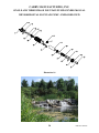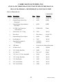
1
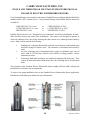
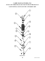
CARRY FOUNTAIN PUMPS
SINGLE and THREE PHASE OWNERS MANUAL
CARRY MANUFACTURING, INC.
1360 Prospect Avenue, Caro, MI 48723-9288
800-49-CARRY or 989-672-2779
FAX: 888-502-8289 or 989-672-2770
Email: [email protected]
www.carrymfg.com
CARRY MANUFACTURING, INC.
SINGLE AND THREE PHASE FOUNTAIN PUMP OWNERS MANUAL
ATTENTION!
IMPORTANT INFORMATION FOR
INSTALLERS OF THIS EQUIPMENT!
THIS EQUIPMENT IS INTENDED FOR INSTALLATION BY TECHNICALLY QUALIFIED
PERSONNEL. FAILURE TO INSTALL IT IN COMPLIANCE WITH NATIONAL AND LOCAL
ELECTRICAL CODES AND WITH CARRY MANUFACTURING RECOMMENDATIONS
MAY RESULT IN ELECTRICAL SHOCK OR FIRE HAZARD, UNSATISFACTORY
PERFORMANCE, AND EQUIPMENT FAILURE. ADDITIONAL INSTALLATION
INFORMATION IS AVAILABLE FROM CARRY MANUFACTURING. CALL TOLL FREE
800-49-2779.
WARNING!
SERIOUS OR FATAL ELECTRICAL SHOCK MAY RESULT FROM FAILURE TO
CONNECT THE MOTOR, CONTROL ENCLOSURES, METAL PLUMBING, AND ALL OTHER
METAL NEAR THE MOTOR OR CABLE, TO THE POWER SUPPLY GROUND TERMINAL
USING WIRE NO SMALLER THAN THE MOTOR CABLE WIRES. TO REDUCE THE RISK
OF ELECTRICAL SHOCK, DISCONNECT POWER BEFORE WORKING ON OR AROUND
ALL ELECTRICAL COMPONENTS. DO NOT USE MOTOR IN SWIMMING AREAS.
CARRY MANUFACTURING, INC.
1360 Prospect Avenue, Caro, MI 48723-9288
Phone: 800-49-CARRY or 989-672-2779
fax: 888-502-8289 or 989-672-2770
Email: [email protected]
www.carrymfg.com
i
Effective 02/2015
CARRY MANUFACTURING, INC.
SINGLE AND THREE PHASE FOUNTAIN PUMP OWNERS MANUAL
TABLE OF CONTENTS
ATTENTION . . . . . . . . . . . . . . . . . . . . . . . . . . . . . . . . . . . . . . . . . . . . . . . . . . . . . . . . . . . . . . . . i
TABLE OF CONTENTS . . . . . . . . . . . . . . . . . . . . . . . . . . . . . . . . . . . . . . . . . . . . . . . . . . . . . ii
STANDARD WARRANTY AND CONDITIONS OF SALE . . . . . . . . . . . . . . . . . . . . . . . . . 1
MODEL NUMBER EXPLANATION . . . . . . . . . . . . . . . . . . . . . . . . . . . . . . . . . . . . . . . . . . . . 5
GENERAL PUMP INSTALLATION . . . . . . . . . . . . . . . . . . . . . . . . . . . . . . . . . . . . . . . . . . . . 6
Single Phase Control Panel and Panel Environment . . . . . . . . . . . . . . . . . . . . . . . . . . . . . 7
Single Phase, 230 Volt Control Panel Installation Instructions . . . . . . . . . . . . . . . 8
3/4 HP, Single Phase Control Panel Wiring Diagram . . . . . . . . . . . . . . . . . . . . . 10
1-1/2 HP, Single Phase Control Panel Wiring Diagram . . . . . . . . . . . . . . . . . . . 11
3 HP, Single Phase Control Panel Wiring Diagram . . . . . . . . . . . . . . . . . . . . . . 12
Carry Designed Three Phase Control Panel and Panel Environment . . . . . . . . . . . . . . . 13
Three Phase Control Panel Installation Instructions . . . . . . . . . . . . . . . . . . . . . . 14
Three Phase Standard and Delux Control Panel Wiring Diagram . . . . . . . . . . . . 14
Three Phase Standard Control Panel . . . . . . . . . . . . . . . . . . . . . . . . . . . . . . . . . . 16
Three Phase Delux Control Panel . . . . . . . . . . . . . . . . . . . . . . . . . . . . . . . . . . . . 17
Franklin Electric Three Phase Control Panel and Panel Environment . . . . . . . . . . . . . . 19
Three Phase Control Panel Installation Instructions . . . . . . . . . . . . . . . . . . . . . . 20
Three Phase Standard Control Panel . . . . . . . . . . . . . . . . . . . . . . . . . . . . . . . . . . 22
Three Phase Delux Control Panel . . . . . . . . . . . . . . . . . . . . . . . . . . . . . . . . . . . . 23
GENERAL INFORMATION . . . . . . . . . . . . . . . . . . . . . . . . . . . . . . . . . . . . . . . . . . . . . . . . . . 24
Franklin Electric Submersible Motors . . . . . . . . . . . . . . . . . . . . . . . . . . . . . . . . . . . . . . . 24
Sumoto Submersible Motors . . . . . . . . . . . . . . . . . . . . . . . . . . . . . . . . . . . . . . . . . . . . . . 25
3/4 HP Vertical Fountain Pump - Exploded View . . . . . . . . . . . . . . . . . . . . . . . . . . . . . 26
1-1/2 HP Vertical Fountain Pump - Exploded View . . . . . . . . . . . . . . . . . . . . . . . . . . . . 28
3 HP Vertical Fountain Pump - Exploded View . . . . . . . . . . . . . . . . . . . . . . . . . . . . . . . 30
3/4 HP Horizontal Fountain Pump - Exploded View . . . . . . . . . . . . . . . . . . . . . . . . . . . 32
1-1/2 HP Horizontal Fountain Pump - Exploded View . . . . . . . . . . . . . . . . . . . . . . . . . . 34
3 HP Horizontal Fountain Pump - Exploded View . . . . . . . . . . . . . . . . . . . . . . . . . . . . . 36
Vertical Fountain Pump Dimensions . . . . . . . . . . . . . . . . . . . . . . . . . . . . . . . . . . . . . . . . 38
Horizontal Fountain Pump Dimensions . . . . . . . . . . . . . . . . . . . . . . . . . . . . . . . . . . . . . . 40
Performance Curves . . . . . . . . . . . . . . . . . . . . . . . . . . . . . . . . . . . . . . . . . . . . . . . . . . . . . 42
Product Use & Safety Information . . . . . . . . . . . . . . . . . . . . . . . . . . . . . . . . . . . . . . . . . 43
MAINTENANCE PROCEDURES . . . . . . . . . . . . . . . . . . . . . . . . . . . . . . . . . . . . . . . . . . . . . 44
Franklin Electric & Sumoto Motors . . . . . . . . . . . . . . . . . . . . . . . . . . . . . . . . . . . . . . . . 45
Replacement Motor Leads . . . . . . . . . . . . . . . . . . . . . . . . . . . . . . . . . . . . . . . . . . . . . . . . 45
ii
Effective 02/2015
CARRY MANUFACTURING, INC.
SINGLE AND THREE PHASE FOUNTAIN PUMP OWNERS MANUAL
TABLE OF CONTENTS
GRAPHS
3/4 Horsepower Performance Curve . . . . . . . . . . . . . . . . . . . . . . . . . . . . . . . . . . . . . . . . 42
1-1/2 Horsepower Performance Curve . . . . . . . . . . . . . . . . . . . . . . . . . . . . . . . . . . . . . . 42
3 Horsepower Performance Curve . . . . . . . . . . . . . . . . . . . . . . . . . . . . . . . . . . . . . . . . . . 42
ILLUSTRATIONS
3/4 HP, Single Phase Control Panel . . . . . . . . . . . . . . . . . . . . . . . . . . . . . . . . . . . . . . . . . 10
Jumper Wire for Single Phase Control Panels . . . . . . . . . . . . . . . . . . . . . . . . . . . 10, 11, 12
1-1/2 HP, Single Phase Control Panel . . . . . . . . . . . . . . . . . . . . . . . . . . . . . . . . . . . . . . . 11
3 HP, Single Phase Control Panel . . . . . . . . . . . . . . . . . . . . . . . . . . . . . . . . . . . . . . . . . . 12
Carry Designed Three Phase Standard and Delux Control Panel Wiring Diagram . . . . 14
Carry Designed Three Phase Standard Control Panel . . . . . . . . . . . . . . . . . . . . . . . . . . . 16
Carry Designed Three Phase Delux Control Panel . . . . . . . . . . . . . . . . . . . . . . . . . . . . . 17
Jumper Wire for Three Phase Panels . . . . . . . . . . . . . . . . . . . . . . . . . . . . . . . . . . . . . . . . 18
Franklin Electric Three Phase Standard Control Panel . . . . . . . . . . . . . . . . . . . . . . . . . . 22
Franklin Electric Three Phase Delux Control Panel . . . . . . . . . . . . . . . . . . . . . . . . . . . . 23
3/4 HP Vertical Fountain Pump - Exploded View . . . . . . . . . . . . . . . . . . . . . . . . . . . . . 26
1-1/2 HP Vertical Fountain Pump - Exploded View . . . . . . . . . . . . . . . . . . . . . . . . . . . . 28
3 HP Vertical Fountain Pump - Exploded View . . . . . . . . . . . . . . . . . . . . . . . . . . . . . . . 30
3/4 HP Horizontal Fountain Pump - Exploded View . . . . . . . . . . . . . . . . . . . . . . . . . . . 32
1-1/2 HP Horizontal Fountain Pump - Exploded view . . . . . . . . . . . . . . . . . . . . . . . . . . 34
3 HP Horizontal Fountain Pump - Exploded View . . . . . . . . . . . . . . . . . . . . . . . . . . . . . 36
3/4 HP Vertical Fountain Pump . . . . . . . . . . . . . . . . . . . . . . . . . . . . . . . . . . . . . . . . . . . . 38
1-1/2 HP Vertical Fountain Pump . . . . . . . . . . . . . . . . . . . . . . . . . . . . . . . . . . . . . . . . . . 38
3 HP Vertical Fountain Pump . . . . . . . . . . . . . . . . . . . . . . . . . . . . . . . . . . . . . . . . . . . . . 38
3/4 HP Horizontal Fountain Pump . . . . . . . . . . . . . . . . . . . . . . . . . . . . . . . . . . . . . . . . . . 40
1-1/2 HP Horizontal Fountain Pump . . . . . . . . . . . . . . . . . . . . . . . . . . . . . . . . . . . . . . . . 40
3 HP Horizontal Fountain Pump . . . . . . . . . . . . . . . . . . . . . . . . . . . . . . . . . . . . . . . . . . . 40
Motor Leads . . . . . . . . . . . . . . . . . . . . . . . . . . . . . . . . . . . . . . . . . . . . . . . . . . . . . . . . . . . 45
TABLES
Single Phase Minimum Submergence . . . . . . . . . . . . . . . . . . . . . . . . . . . . . . . . . . . . . . . . 9
Three Phase Minimum Submergence . . . . . . . . . . . . . . . . . . . . . . . . . . . . . . . . . . . . 15, 21
Transformer . . . . . . . . . . . . . . . . . . . . . . . . . . . . . . . . . . . . . . . . . . . . . . . . . . . . . . . . . . . 18
Circuit Breaker . . . . . . . . . . . . . . . . . . . . . . . . . . . . . . . . . . . . . . . . . . . . . . . . . . . . . . . . . 18
Motor Contactor and Overload . . . . . . . . . . . . . . . . . . . . . . . . . . . . . . . . . . . . . . . . . . . . 18
Vertical Fountain Pump Dimensions . . . . . . . . . . . . . . . . . . . . . . . . . . . . . . . . . . . . . . . . 39
Horizontal Fountain Pump Dimensions . . . . . . . . . . . . . . . . . . . . . . . . . . . . . . . . . . . . . . 41
Franklin Electric and Sumoto Motors . . . . . . . . . . . . . . . . . . . . . . . . . . . . . . . . . . . . . . . 45
Complete the Warranty & Registration Card today to ensure that your pump’s warranty is
activated!
iii
Effective 02/2015
CARRY MANUFACTURING, INC.
SINGLE AND THREE PHASE FOUNTAIN PUMP OWNERS MANUAL
This page intentionally left blank.
iv
Effective 02/2015
CARRY MANUFACTURING, INC.
SINGLE AND THREE PHASE FOUNTAIN PUMP OWNERS MANUAL
STANDARD WARRANTY AND CONDITIONS OF SALE
PRELIMINARY INFORMATION: Any preliminary drawings and illustrative materials used in the
specification build-up process show general arrangement and approximate dimensions only.
Certified drawings will be submitted after receipt of an order, if required.
PRICES: Any listed price is subject to change without notice. Orders are accepted with the
understanding that the product will be billed at the price in effect at the time of shipment, unless
otherwise specified by Carry Manufacturing, Inc.
QUOTATIONS: Any quotation 60 days old is subject to change without notice. The price of each
order is subject to the resource availability and costs incurred by Carry Manufacturing, Inc. at the
time of manufacture.
FREIGHT: F.O.B. Carry’s factory in Caro, Michigan. Catalog weights are careful estimates, but
they are not guaranteed. No allowance will be made for cartage at destination.
TAXES AND OTHER CHARGES: The prices do not include any Federal, State or Local sales, use
or other taxes, or brokerage fees that may be applicable. The amount of any such applicable taxes
or fees will be added to the invoice at the rate in effect at the time of shipment.
ACCEPTANCE: No order shall be binding upon Carry Manufacturing, Inc. until accepted in writing
by an authorized official at its home office in Caro, Michigan. Any contract for the sale of product
and these Conditions of Sale, shall be governed by and construed according to the Uniform
Commercial Code as adopted in the State of Michigan.
If the product quoted is not approved by the Consulting Engineer, Carry Manufacturing, Inc.
assumes no responsibility to furnish any item manufactured by others.
CREDIT: Credit worthiness of a Purchaser will be determined upon receipt of the contract. Credit
terms, if authorized, are subject to change during the life of the contract if the financial condition
of the Purchaser changes.
CANCELLATION: Cancellation of orders will be accepted with the understanding that Carry
Manufacturing, Inc. will be entitled to reimbursement for expenses incurred at the time of
cancellation, including any and all special engineering, design, tooling, manufacturing, storage or
transportation costs.
TERMS, PAYMENT & INVOICING: Standard payment terms are NET 30 days from the date of
the invoice. Retaining a percentage of the contract sale amount is prohibited without prior, written
agreement. Payment must be made in U.S. Funds. An invoice will be rendered as of the date the
product is ready for shipment. A service fee of 1-1/2% per month on all invoices over 30 days past
due will be imposed. In the event of any default by the Purchaser, Carry Manufacturing, Inc. shall
have the right to repossess the product as well as all other rights afforded to a conditional seller
under the provisions of the Uniform Conditional Sales Act and any other applicable laws.
1
Effective 02/2015
CARRY MANUFACTURING, INC.
SINGLE AND THREE PHASE FOUNTAIN PUMP OWNERS MANUAL
STANDARD WARRANTY AND CONDITIONS OF SALE
MANUALS: One (1) owner’s/service manual will be provided with each purchase of a single pump.
Additional owner’s/service manuals are available fro $15.00 each.
DELIVERY: The estimated shipping date is based on the production time required to process the
order commencing with the date the order is accepted by Carry Manufacturing, Inc. In the event it
is necessary to revise the design, specifications, or Conditions of Sale, the shipping date shall be
automatically extended by the period of time required to achieve the mutually agreed upon
correction or adjustments of the design, specifications or Conditions of Sale.
Carry Manufacturing, Inc. reserves the right to make shipment of completed segments of an order
and pro rate the invoice for those segments as shipments are made.
DELAYS IN DELIVERY: Carry Manufacturing, Inc. shall not be responsible for any delay or for
any damages suffered by the Purchaser by reason of any delay due to fires, strikes, riots, Acts of
God, priorities, Government orders or restriction, delays in transportation, delays of suppliers of
materials or parts, inability to obtain necessary labor, or other causes beyond the control of Carry
Manufacturing, Inc. In the event of such a delay, the shipping date shall be extended for a period of
time equal to the time lost by reason of such a delay.
Any product held more than three (3) weeks after the estimated shipping date at the Purchaser’s
request will be stored at the Purchaser’s expense unless otherwise agreed upon.
DAMAGE OR LOSS IN TRANSIT: Delivery of the product to a carrier at Carry Manufacturing’s
plant or other shipping point selected by Carry Manufacturing shall constitute delivery to the
Purchaser. Regardless of freight payment, all risk, loss or damage in transit shall pass to the
Purchaser at that time. The Purchaser shall make claims for loss or damage to product while in
transit, against the carrier and not against Carry Manufacturing, Inc. Carry Manufacturing, Inc. will
assist the Purchaser in securing satisfactory adjustment of such claims.
BETWEEN SHIPMENT AND PAYMENT: The Purchaser shall be responsible for the care,
maintenance and protection of the material or product after delivery. The Purchaser agrees to
provide and maintain adequate insurance for the product or materials shipped to the Purchaser
against loss or damage by fire, explosion or other causes during the time between shipment and final
payment in an amount fully protecting Carry Manufacturing, Inc.
The title and right of possession to the machinery shall remain with Carry Manufacturing, Inc. and
the machinery shall remain personal property irrespective of attachment to, or location on, any
foundation or in any structure, until all payments shall have been made in cash. The Purchaser will
do all acts necessary to protect the above title and right.
INSTALLATION: Unless specifically stated otherwise, all material or product shall be installed and
placed in service by, at the expense of, and under the exclusive responsibility of the Purchaser.
2
Effective 02/2015
CARRY MANUFACTURING, INC.
SINGLE AND THREE PHASE FOUNTAIN PUMP OWNERS MANUAL
STANDARD WARRANTY AND CONDITIONS OF SALE
RETURNED PRODUCT: Authorization and shipping instructions for the return of any product must
first be obtained by the Purchaser from Carry. Otherwise shipment will be refused. Only unused
standard product or materials of current design by Carry will be considered for return. Custom
products cannot be returned for credit. If the returned product is in sellable condition, a credit
memorandum will be issued minus a minimum restocking charge of 15% and minus all
transportation charges paid by Carry.
PUMP WARRANTY REGISTRATION CARD AND PROOF OF PURCHASE: Within 30 days
of the purchase of the pump, Purchaser shall mail to Carry by certified mail, return receipt requested,
the pump warranty registration card accompanied by proof of purchase from the retail seller
indicating the date and purchase price of the pump at issue. This warranty is void unless the
warranty registration card and proof of purchase are provided to Carry as set out above and are on
file with Carry.
LIMITED WARRANTY: Carry warrants the product sold by it to be free from defects in materials
and workmanship for a period of one (1) year from the date of purchase of the pump as verified by
the product warranty registration card and proof of purchase provided to Carry by Purchaser.
WARRANTY DISCLAIMER: This warranty does not apply to the product if used in an aquacultural
application or to pumps that have been subject to mis-use (including use in a manner inconsistent
with the design of the pump), abuse, neglect, accident or improper installation or maintenance, or
to pumps that have been altered or repaired by anyone other than Carry. The warranties in this
agreement are in lieu of all other warranties, express or implied, including without limitation, any
warranties of merchantability or fitness for a particular purpose, said warranties being expressly
disclaimed.
WARRANTY AMENDMENTS: Prior or subsequent courses of dealing, trade usage and verbal
agreements not reduced to a writing signed by Carry, to the extent they differ from, modify, add to
or detract from this warranty shall not be binding upon Carry. There are no agreements, promises
or understandings, either verbal or written, that are not fully expressed in this warranty. No
statements, recommendations or assistance by either party have been relied upon by either party nor
shall they be relied upon and shall not constitute a waiver by either party of any of the provisions
hereof. This warranty may be amended or altered only if agreed to in writing signed by Carry.
LIMITED REMEDY: Carry and Purchaser agree the repair or replacement of the pump at issue is
a commercially reasonable allocation of risk and, therefore, Purchaser agrees that its sole and
exclusive remedy against Carry shall be limited to the repair or replacement of the pump at issue.
This exclusive remedy shall not be deemed to have failed of its essential purpose so long as Carry
is willing and able to repair or replace the pump at issue. In the event Carry is unable to repair or
replace the pump at issue in a manner acceptable to Purchaser, or in the event it shall be determined
by a court having jurisdiction thereof that any provisions of this warranty are unconscionable or fail
in its essential purpose, then the maximum liability of Carry shall be that as set forth in the
paragraph next following entitled “Limitation on Liability.”
3
Effective 02/2015
CARRY MANUFACTURING, INC.
SINGLE AND THREE PHASE FOUNTAIN PUMP OWNERS MANUAL
STANDARD WARRANTY AND CONDITIONS OF SALE
LIMITATION ON LIABILITY: Carry shall not be liable for any loss, damage or injury resulting
from delay in delivery or installation of the pump or for any failure to perform which is due to
circumstances beyond its control. Carry and Purchaser agree it is a commercially reasonable
allocation of risk that the maximum liability, if any, of Carry for all damages, including without
limitation contract damages and damages for injuries to persons or property, whether arising from
Carry’s breach of this agreement, breach of warranty, negligence, strict liability or other tort, is
limited to an amount not to exceed the purchase price of the pump at issue in the dispute and said
liability is so limited. In no event shall Carry be liable to Purchaser for any incidental, consequential
or special damages, including without limitation, lost revenues and profits, even if it has been
advised of the possibility of such damages.
WARRANTY CLAIM PROCEDURE: The warranty is valid only if the following conditions are
complied with by the Purchaser. Purchaser shall notify Carry in writing of the defect in the pump
at issue within 30 days of discovery of the defect. The notice shall include with it copies of the
warranty card, proof of purchase and the return receipt signed by a representative of Carry as
provided above. In the event repair or replacement of the pump at issue is approved by Carry,
Purchaser shall, upon written notice by Carry of the approval, return the pump to Carry, freight
prepaid. Carry will return the repaired or replaced pump to Purchaser, freight prepaid. The repair
or replacement of the pump shall not extend the duration of the one-year warranty term.
GOVERNING LAW: This warranty shall be governed and controlled by and enforced in accordance
with the laws of the State of Michigan, U.S.A., in all respects.
FORUM: The parties agree they are of equal bargaining power and irrevocably submit to the
jurisdiction and venue of the Circuit Court for the County of Tuscola, State of Michigan or, if
original jurisdiction can be established, the United States District Court for the Eastern District of
Michigan, Northern Division, with respect to any performance or breach of this agreement. The
parties hereby stipulate that the venues referenced in this agreement are convenient to each of them.
REMINDER:
Mail in your WARRANTY REGISTRATION CARD
today!
4
Effective 02/2015
CARRY MANUFACTURING, INC.
SINGLE AND THREE PHASE FOUNTAIN PUMP OWNERS MANUAL
FOUNTAIN PUMP
MODEL NUMBER EXPLANATION
Example No. F20150-123H
F
=
Fountain Pump
2
=
Discharge:
(2) = 2" Female NPT
(3) = 3" Female NPT
0150
=
Horsepower:
(0075) = 3/4 Horsepower
(0150) = 1-1/2 Horsepower
(0300) = 3 Horsepower
1
=
Phase:
(1) = Single Phase
(3) = Three Phase
23
=
Voltage:
(20) = 200V (Three Phase Only)
(23) = 230V (Single or Three Phase)
H
=
Orientation:
(V) = Vertical
(H) = Horizontal
Thus a F20150-123H is a Fountain Pump with a 2" Female NPT Discharge, 1-1/2
Horsepower, Single Phase, 230V Horizontal design.
Please note:
All Carry Fountain Pumps come standard with a 30' power lead.
Other lengths are available upon request.
5
Effective 02/2015
CARRY MANUFACTURING, INC.
SINGLE AND THREE PHASE FOUNTAIN PUMP OWNERS MANUAL
GENERAL PUMP INSTALLATION
In this section, information has been provided on the installation of the Carry Fountain Pump and
its components. The installation will include both the Carry Fountain Pump and the control panel,
if applicable. Carry’s Fountain Pump was designed to pump high volumes of water. Both the
Franklin Electric and Sumoto motors were specifically developed to live under water. The control
panel was designed to provide accurate starting, running and overload protection.
The pump must be installed and operated correctly to keep it working at its utmost efficiency. This
owner’s manual has been developed to provided the owner and installer with as much information
as possible to ensure satisfactory installation and operation. The following pages detail the specific
instructions for each component of the installation. Following the installation information are
several general information tips.
Before installation, check the bottom of the sump for debris, sand or muck. Remove as much as
possible. The presence of debris in the sump could damage your submersible pump. Ideally, your
sump site should be designed to prevent the accumulation of debris and sand.
Connect the discharge pipe to the pump discharge. Carry Fountain Pumps with a 2" discharge have
2" Female NPT threads for connecting to the discharge piping. Carry recommends using 2"
Schedule 40 PVC male adapters to connect the discharge pipe to the Carry Fountain Pump. Carry
Fountain Pumps with a 3" discharge have 3" Female NPT threads for connecting to the discharge
piping. Use 3" Schedule 40 PVC male adapters to connect the discharge pipe to the Carry Fountain
Pump.
DO NOT lower the pump into the wet well by the power cord. This could damage the cord and
cause an electrical hazard in the future. Position the pump in the center of the sump so the discharge
pipe may be installed easier. Use nylon cord or electrical tape to attach the power cord vertically
along the pump and the discharge pipe to avoid breakage. Make the final connections to the
discharge pipe.
WARNING- Do not lift the pump using the power lead. Electrical shorts can occur and could
damage the pump’s motor and control panel.
CAUTION: USE EXTREME CARE WHEN WORKING AROUND PUMPS AND
ELECTRICAL CONTROLS!
6
Effective 02/2015
CARRY MANUFACTURING, INC.
SINGLE AND THREE PHASE FOUNTAIN PUMP OWNERS MANUAL
FRANKLIN ELECTRIC SINGLE PHASE CONTROL PANEL
AND PANEL ENVIRONMENT
Franklin Electric control panels meet UL
requirements for Type 3R enclosures. They are
suitable for indoor and outdoor applications
within temperatures of +14oF (-10oC) to 122oF
(50oC). Operating control panels below +14oF
can cause reduced starting torque and loss of
overload protection, when overloads are located
in control panels. During the coldest weather,
temperature may be kept above +14oF by an
enclosure around the control panel and using heat
tape or a small light bulb in the enclosure as a
heat source.
Control panels should never be mounted in direct sunlight or high temperature locations, as this will
cause shortened capacitor life and the unnecessary tripping of overload protectors. A ventilated
enclosure, painted white to reflect heat, is recommended for outdoor, high temperature locations.
The worst place to mount a control panel is in a damp well pit, or other humid location, as this
accelerates component failure from voltage breakdown and corrosion.
Control panels with voltage relays are designed for vertical upright mounting only. Mounting in
other positions will affect the operation of the relay.
Adapted from “Submersible Motors: Application, Installation, Maintenance.” Franklin Electric,
September 1, 1993.
Please note: Carry 3/4 and 1-1/2 Horsepower, Single Phase, Fountain Pumps are available with
either 2-wire or 3-wire motors. Carry Fountain Pumps with either Franklin Electric or Sumoto 2wire motors DO NOT require the use of a separate control panel. These pumps may be wired
directly into a circuit breaker or other type of disconnect. These pumps do require proper overload
protection. Please specify 2-wire or 3-wire when ordering. All 3 Horsepower, Single Phase,
Fountain Pumps have 3-wire motors only. If your pump has a 2-wire motor, you may disregard the
following information on control panel wiring.
7
Effective 02/2015
CARRY MANUFACTURING, INC.
SINGLE AND THREE PHASE FOUNTAIN PUMP OWNERS MANUAL
FRANKLIN ELECTRIC SINGLE PHASE, 230 VOLT CONTROL PANELS
INSTALLATION INSTRUCTIONS
Before any connections are made, verify that the power supply voltage, hertz, and KVA capacity
match the motor requirements. Refer to Table 13 on page 13 of the Franklin Electric Submersible
Motors Application, Installation and Maintenance Manual.
Illustrations of the electrical wiring diagrams have been provided for each horsepower pump as an
example of how the control panel should be wired. Note: A wiring diagram should also have been
included with the control panel. Following are detailed instructions of how to connect the wiring
to the control panel. While following the written instructions, verify the connections with the
control panel drawing that corresponds to the horsepower of the motor. The pump and control panel
warranty will be voided for failure to follow these instructions. Make sure that all the connections
are tight. Failure to do so, could result in damage to your pump system. These instructions refer
to SINGLE PHASE, 230 VOLT SYSTEMS ONLY!
Make all electrical connections from the motor lead to the control panel per the detailed instructions.
Install all ground rods and connect all ground wires. See detailed instructions for each component.
8
Effective 02/2015
CARRY MANUFACTURING, INC.
SINGLE AND THREE PHASE FOUNTAIN PUMP OWNERS MANUAL
FRANKLIN ELECTRIC SINGLE PHASE, 230 VOLT CONTROL PANELS
WIRING INSTRUCTIONS
The incoming power source should be Single Phase, 230 Volts. There will be three (3) wires from
the incoming power source. Two (2) of the wires will be connected to “L1" and “L2" on the
terminal strip inside the control panel and the ground wire will be connected to the ground lug inside
the control panel.
To connect the pump to the control panel, connect the wires as follows:
1.
The white (or yellow) wire from the pump to the “Y” terminal on the terminal strip
inside the control panel.
2.
The black wire from the pump to the “B” terminal on the terminal strip inside the
control panel.
3.
The red wire from the pump to the “R” terminal on the terminal strip inside the
control panel.
4.
The ground wire from the pump to the ground lug inside the control panel.
Ground the control panel as follows:
1.
Use wire at least as large as the line conductors.
2.
Connect the wire to the ground lug and a ground rod.
We recommend this procedure when installing your control panel. If the control panel
is not grounded with a ground rod, your pumping system could be seriously damaged.
CAUTION: Failure to ground the control panel frame can result in a serious electrical
shock hazard if a circuit fault occurs.
Optional Low Level Shut Off (Sensor) Float connected as follows:
1.
The black wire from the float to the “L2" terminal on the terminal strip inside the
control panel.
2.
The white wire from the float to the “SW” terminal on the terminal strip inside the
control panel.
The float should be positioned at the minimum submergence level of the pump to prevent the pump
running “dry.” Minimum Submergence for each pump is a follows:
Table 1: Single Phase Minimum Submergence
Single Phase Fountain Pump
Vertical
Horizontal
3/4 HP
24"
20"
1-1/2 HP
36"
24"
3 HP
34"
30"
9
Effective 02/2015
CARRY MANUFACTURING, INC.
SINGLE AND THREE PHASE FOUNTAIN PUMP OWNERS MANUAL
3/4 HORSEPOWER SINGLE PHASE CONTROL PANEL
Model # 282-407-50 or 282-407-50T
Illustration 2: Jumper Wire
Note: If no optional control
switch or device (sensor float)
is used, install a jumper wire
from L2 to SW on the terminal
strip of the control panel. With
this jumper installed, the pump
will start when the circuit
breaker or disconnect switch is
engaged. Use caution when
operating a submersible pump
in this manner.
Illustration 1
Item #:
Qty:
Description:
Part No.:
1
2
3
4
5
6*
1
Contactor
155-325-102
1
Relay
155-031-102
1
Start Capacitor
275-464-105
1
Run Capacitor
156-362-102
1
Terminal Block
--1
Auto-Off-Test Switch
SQD-ZB4BD8
1
Switch Contact Block
SQDZB4BZ103
* Auto-Off-Test Switches are included on delux control panels only.
10
Effective 02/2015
CARRY MANUFACTURING, INC.
SINGLE AND THREE PHASE FOUNTAIN PUMP OWNERS MANUAL
1-1/2 HORSEPOWER SINGLE PHASE CONTROL PANEL
Model #: 282-300-81 or 282-300-81T
Illustration 2: Jumper Wire
Note: If no optional control
switch or device (sensor float)
is used, install a jumper wire
from L2 to SW on the terminal
strip of the control panel. With
this jumper installed, the pump
will start when the circuit
breaker or disconnect switch is
engaged. Use caution when
operating a submersible pump
in this manner.
Illustration 3
Item #:
Qty:
Description:
Part No.:
1
2
3
4
5
6*
1
Contactor
155-325-102
1
Relay
155-031-102
1
Start Capacitor
275-464-113
1
Run Capacitor
155-328-102
1
Terminal Block
--1
Auto-Off-Test Switch
SQD-ZB4BD8
1
Switch Contact Block
SQDZB4BZ103
*Auto-Off-Test Switches are included on delux control panels only.
11
Effective 02/2015
CARRY MANUFACTURING, INC.
SINGLE AND THREE PHASE FOUNTAIN PUMP OWNERS MANUAL
3 HORSEPOWER SINGLE PHASE CONTROL PANEL
Model #: 282-302-83 or 282-302-83T
Illustration 2: Jumper Wire
Note: If no optional control
switch or device (sensor float)
is used, install a jumper wire
from L2 to SW on the terminal
strip of the control panel. With
this jumper installed, the pump
will start when the circuit
breaker or disconnect switch is
engaged. Use caution when
operating a submersible pump
in this manner.
Illustration 4
Item #:
Qty:
Description:
Part No.:
1
2
3
4
5
6
7
8*
1
Contactor
1
Relay
1
Start Capacitor
1
Run Capacitor
1
Terminal Block
1
Start Overload
1
Main Overload
1
Auto-Off-Test Switch
1
Switch Contact Block
*Auto-Off-Test Switches are included on delux control panels only.
12
155-325-102
155-031-102
275-463-123
155-327-109
--275-411-108
275-411-115
SQD-ZB4BD8
SQDZB4BZ103
Effective 02/2015
CARRY MANUFACTURING, INC.
SINGLE AND THREE PHASE FOUNTAIN PUMP OWNERS MANUAL
THREE PHASE CONTROL PANEL AND PANEL ENVIRONMENT
Carry designed Three Phase Control Panels use Type 3R enclosures. They are suitable for indoor
and outdoor applications within temperatures of +14oF (-10oC) to 122oF (50oC). Operating control
panels below +14oF can cause reduced starting torque and loss of overload protection, when
overloads are located in control panels. During the coldest weather, temperature may be kept above
+14ºF by an enclosure around the control panel and using heat tape or a small light bulb in the
enclosure as a heat source.
Control panels should never be mounted in direct sunlight or high temperature locations, as this will
cause shortened life expectancy of the components. A ventilated enclosure, painted white to reflect
heat, is recommended for outdoor, high temperature locations.
The worst place to mount a control panel is in a damp well pit, or other humid location, as this
accelerates component failure from voltage breakdown and corrosion.
13
Effective 02/2015
CARRY MANUFACTURING, INC.
SINGLE AND THREE PHASE FOUNTAIN PUMP OWNERS MANUAL
THREE PHASE CONTROL PANEL INSTALLATION INSTRUCTIONS
Before any connections are made, verify that the power supply voltage, hertz and KVA capacity
match the motor requirements. Refer to Table 22 on page 22 of the Franklin Electric Submersible
Motor Application, Installation and Maintenance manual.
Illustrations of the electrical wiring diagrams have been provided for a standard and delux panel as
an example of how the control panel should be wired. Note: A wiring diagram should also have
been included with the control panel. Below are detailed instructions of how to connect the wiring
to the control panel. While following the written instructions, verify the connections with the
control panel drawing that corresponds to your control panel. Special control panel diagrams (with
special components or additional functionality) will be placed at the back of this manual. Pump and
control panel warranty will be voided for failure to follow these instructions. Make sure that all the
connections are tight. Failure to do so, could result in damage to your pump system. These
instructions refer to THREE PHASE SYSTEMS ONLY! Make all electrical connections from the
motor lead to the control panel per the detailed instructions. Install all ground rods and connect all
ground wires. See detailed instructions for each component.
THREE PHASE STANDARD and DELUX CONTROL PANEL
WIRING DIAGRAM
Illustration 5
14
Effective 02/2015
CARRY MANUFACTURING, INC.
SINGLE AND THREE PHASE FOUNTAIN PUMP OWNERS MANUAL
WIRING INSTRUCTIONS
The incoming power source should be three phase, and either 200 or 230 volts. There will be four
(4) wires from the incoming power source. Three (3) of the wires will be connected to "L1" "L2"
and “L3" on the terminal strip inside the control panel and the ground wire will be connected to the
ground lug inside the control panel.
To connect the pump to the control panel, connect the wires as follows:
1)
The black wire from the pump to the "1T1" on the terminal strip inside the control
panel.
2)
The white (or yellow) wire from the pump to the "1T2" on the terminal strip inside
the control panel
3)
The red wire from the pump to the "1T3" on the terminal strip inside the control
panel.
4)
The ground wire from the pump to the ground lug inside the control panel.
Or as specified on the specific wiring diagram located at the back of this manual. Note: if the pump
runs backwards, swap two of the leads, either 1T1 and 1T2 or 1T1 and 1T3 or 1T2 and 1T3.
Ground the control panel as follows:
1)
Use a minimum of 8 AWG wire for services up to 125 AMPS.
2)
Use a minimum of 6 AWG wire for services up to 175 AMPS.
3)
Use a minimum of 4 AWG wire for services up to 250 AMPs.
4)
Connect the wire to the ground lug and a ground rod.
We recommend this procedure when installing your control panel. If the control panel is
not grounded with a ground rod your pumping system could be seriously damaged.
CAUTION: Failure to ground the control panel frame can result in a
serious electrical shock hazard if a circuit fault occurs.
Optional Low Level Shut Off (Sensor) Float connected as follows:
1.
The black wire from the float to the “B" terminal on the terminal strip inside the
control panel.
2.
The white wire from the float to the “R” terminal on the terminal strip inside the
control panel.
The float should be positioned at the minimum submergence level of the pump to prevent the
pump running “dry.” Minimum Submergence for each pump is a follows:
Table 2: Three Phase Minimum Submergence
Three Phase Fountain Pump
Vertical
Horizontal
3/4 HP
24"
20"
1-1/2 HP
36"
24"
3 HP
31"
30"
15
Effective 02/2015
CARRY MANUFACTURING, INC.
SINGLE AND THREE PHASE FOUNTAIN PUMP OWNERS MANUAL
THREE PHASE STANDARD CONTROL PANEL
Illustration 6
Item #:
1
2
3
4
5
6
7
8
9
10
11
12*
Qty:
1
1
1
1
1
1
1
1
2
1
1
1
Description:
NEMA 3R Enclosure (20" x 16" x 8")
Sub Panel
Disconnect Switch w/ Handle
Transformer
Circuit Breaker - 1 AMP, 1 POLE
Circuit Breaker - 1 AMP, 2 POLE
Circuit Breaker - 3 POLE
Terminal Strip
Ground Lug
Overload Relay
Contactor
Lightning Arrestor (optional)
16
Part No.:
20R1606LP
20P16
KSR3.40 ASSEMBLY
See Table on page 18.
WMZS1D01
WMZS2D01
See Table on page 18.
----See Table on page 18.
See Table on page 18.
155-440-902
Effective 02/2015
CARRY MANUFACTURING, INC.
SINGLE AND THREE PHASE FOUNTAIN PUMP OWNERS MANUAL
THREE PHASE DELUX CONTROL PANEL
Illustration 7
Item #:
1
2
3
4
5
6
7
8
9
10
11
12
13
14*
Qty:
1
1
1
1
1
1
1
1
1
1
1
2
1
1
1
Description:
NEMA 3R Enclosure (20" x 16" x 8")
Sub Panel
Disconnect Switch w/ Handle
Pump Run Light
Transformer
Auto-Off-Test Switch
Contact Block
Circuit Breaker - 1 AMP, 1 POLE
Circuit Breaker - 1 AMP, 2 POLE
Circuit Breaker - 3 POLE
Terminal Strip
Ground Lug
Overload Relay
Contactor
Lightning Arrestor (optional)
17
Part No.:
20R1606LP
20P16
KSR3.40 ASSEMBLY
ML-GREEN
See Table on page 18.
SQD-ZB4BD8
SQDZB4BZ103
WMZS1D01
WMZS2D01
See Table on page 18.
----See Table on page 18.
See Table on page 18.
155-440-902
Effective 02/2015
CARRY MANUFACTURING, INC.
SINGLE AND THREE PHASE FOUNTAIN PUMP OWNERS MANUAL
JUMPER WIRE FOR THREE PHASE PANELS
Note: If no optional control switch or device (sensor float) is used,
install a jumper wire from B to R on the terminal strip of the
control panel. With this jumper wire installed, the pump will start
when the circuit breaker or disconnect switch is engaged. Use
caution when operating a submersible pump in this manner.
Illustration 8
THREE PHASE CONTROL PANEL PARTS
Table 3: Transformer
TRANSFORMER
200V
230V
SQD9070T100D3 or
PH100MGJ
SQD9070T100D1 or
PH100MQMJ
Table 4: Circuit Breaker
CIRCUIT BREAKER
HP
200V
230V
3/4 HP
WMZT3D06
WMZT3D06
1-1/2 HP
WMZT3D10
WMZT3D08
3 HP
WMZT3D15
WMZT3D13
Table 5: Motor Contactor and Overload
CONTACTOR and OVERLOAD
HP
CONTACTOR
200V
230V
GH15BN-3-10A
GH15BN-3-10A
RTD32-600
RTD32-400
GH15BN-3-10A
GH15BN-3-10A
RTD32-900
RTD32-600
GH15DN-3-10A
GH15CN-3-10A
3/4 HP
OVERLOAD
CONTACTOR
1-1/2 HP
OVERLOAD
CONTACTOR
3 HP
RTD32-1400
RTD32-1100
OVERLOAD
See Tables 28 and 29 on pages 28 and 29 of the Franklin Electric Submersible Motor Application,
Installation and Maintenance manual for more information on setting adjustable relays. Your
control panel should have been set to the correct value at the factory. It is a good idea to double
check this setting.
18
Effective 02/2015
CARRY MANUFACTURING, INC.
SINGLE AND THREE PHASE FOUNTAIN PUMP OWNERS MANUAL
FRANKLIN ELECTRIC THREE PHASE CONTROL PANELS
The Technology behind Smartstart
Smart - Start safely even without calibration! Smartstart patent
pending technology predicts a safer operation range for your motor
and protects the motor if the starter’s FLA dial is set too high.
Intelligent - Smartstart detects if your starter needs to be
calibrated, protecting you from operators trying to overcome
motor jams or problems by over-setting the overload. With
Smartstart enabled, if the starter isn’t in range, it alarms and trips
notifying you before damage occurs.
Active - Smartstart detects harmful extended starting conditions
with maximum time to start. Monitors motor inrush current conditions and trips if the motor doesn’t
start within 10 seconds, regardless of FLA setting.
Ingenious - Active current monitoring provides superior protection against locked rotor and stall
conditions, tripping faster than a standard inverse trip curve.
Integrated electronic motor and pump protection
•
Class S electronic overload
•
specifically designed protection for submersible motors
•
built in 1.15 service factor compensation
•
Underload (dry-run protection)
•
Current phase unbalance protection
•
Cycle fault protection
•
Locked rotor and stall protection
•
Out of Calibration - detects if overload FLA dial is improperly set
Multi-voltage operating range with automatic I/O
•
Accepts 200-600 VAC directly - true plug and play
•
Includes a dry contact auto-run input and fault relay output
•
Optional run timer - adjustable up to 12 hours (Starter will run for selected time then return to
OFF until another run command is given)
Industrial grade construction
•
Door mounted heavy-duty HOA switch
•
Housed in an outdoor rated, gasketed, NEMA 3R enclosure
•
NEMA/IEC rated magnetic contactors feature 2.5 million electrical cycles at full rated current
Optional circuit breaker disconnect (Service Entrance rated)
•
UL 489 circuit breaker provides branch and short circuit protection
•
No fuses required - saves time and money
•
Lockable handle for safety
19
Effective 02/2015
CARRY MANUFACTURING, INC.
SINGLE AND THREE PHASE FOUNTAIN PUMP OWNERS MANUAL
FRANKLIN ELECTRIC THREE PHASE CONTROL PANEL
INSTALLATION INSTRUCTIONS
Before any connections are made, verify that the power supply voltage, hertz, and KVA capacity
match the motor requirements. Refer to Table 22 on page 22 of the Franklin Electric Submersible
Motor Application, Installation and Maintenance manual.
Illustrations of the electrical wiring diagrams have been provided for a standard and delux panel as
an example of how the control panel should be wired. Note: A wiring diagram should also have
been included with the control panel. Below are detailed instructions of how to connect the wiring
to the control panel. While following the written instructions, verify the connections with the
control panel drawing that corresponds to your control panel. Special control panel diagrams (with
special components or additional functionality) will be placed at the back of this manual. Pump and
control panel warranty will be voided for failure to follow these instructions. Make sure that all the
connections are tight. Failure to do so, could result in damage to your pump system. These
instructions refer to THREE PHASE SYSTEMS ONLY! Make all electrical connections from the
motor lead to the control panel per the detailed instructions. Install all ground rods and connect all
ground wires. See detailed instructions for each component.
20
Effective 02/2015
CARRY MANUFACTURING, INC.
SINGLE AND THREE PHASE FOUNTAIN PUMP OWNERS MANUAL
FRANKLIN ELECTRIC THREE PHASE CONTROL PANEL
WIRING INSTRUCTIONS
The incoming power source should be three phase, and either 200 or 230 volts. There will be four
(4) wires from the incoming power source. Three (3) of the wires will be connected to "L1", "L2"
and “L3" on the Breaker/Disconnect Switch inside the control panel and the ground wire will be
connected to the ground lug inside the control panel.
To connect the pump to the control panel, connect the wires as follows:
1)
The black wire from the pump to the "T1" on the contactor inside the control panel.
2)
The white (or yellow) wire from the pump to the "T2" on the contactor inside the
control panel
3)
The red wire from the pump to the "T3" on the contactor inside the control panel.
4)
The ground wire from the pump to the ground lug inside the control panel.
Or as specified on the specific wiring diagram located at the back of this manual. Note: if the pump
runs backwards, swap two of the leads, either T1 and T2 or T1 and T3 or T2 and T3.
Ground the control panel as follows:
1)
Use a minimum of 8 AWG wire for services up to 125 AMPS.
2)
Use a minimum of 6 AWG wire for services up to 175 AMPS.
3)
Use a minimum of 4 AWG wire for services up to 250 AMPs.
4)
Connect the wire to the ground lug and a ground rod.
We recommend this procedure when installing your control panel. If the control panel is
not grounded with a ground rod your pumping system could be seriously damaged.
CAUTION: Failure to ground the control panel frame can result in a
serious electrical shock hazard if a circuit fault occurs.
Optional Low Level Shut Off (Sensor) Float connected as follows:
1.
The black wire from the float to the “B" terminal on the terminal strip inside the
control panel.
2.
The white wire from the float to the “R” terminal on the terminal strip inside the
control panel.
The float should be positioned at the minimum submergence level of the pump to prevent the
pump running “dry.” Minimum Submergence for each pump is a follows:
Table 2: Three Phase Minimum Submergence
Three Phase Fountain Pump
Vertical
Horizontal
3/4 HP
24"
20"
1-1/2 HP
36"
24"
3 HP
31"
30"
21
Effective 02/2015
CARRY MANUFACTURING, INC.
SINGLE AND THREE PHASE FOUNTAIN PUMP OWNERS MANUAL
FRANKLIN ELECTRIC THREE PHASE STANDARD CONTROL PANEL
L1
L2
T1
T2
L3
A1
H1
D1
02
H4
O1
D3
D2
M1
T3
A2
Illustration 9
Item #:
1
2
3
4
Qty:
1
1
1
1
Description:
Enclosure
Disconnect Handle
Selector Switch
Breaker/Disconnect Switch
5
6
7
8
1
1
1
1
Contactor
Ground Lugs
Terminal Strip
Starter Module
Part #:
--EHU-1/12
HW1S-3TFO
TD125NU FTU 125 15A
for 3/4 & 1-1/2 HP Pumps
TD125NU FTU 125 20A for 3HP Pumps
MRC-18B-24VAC
--SK4
RG41
22
Effective 02/2015
CARRY MANUFACTURING, INC.
SINGLE AND THREE PHASE FOUNTAIN PUMP OWNERS MANUAL
FRANKLIN ELECTRIC THREE PHASE DELUX CONTROL PANEL
L1
L2
L3
A1
D1
O2
O1
H1
D2
H3
H2
H4
H2
H1
M1
T1
T2
T3
T1
A2
X2
N/A
XF
X1
Illustration 10
Item #:
1
2
3
4
Qty:
1
1
1
1
Description:
Enclosure
Disconnect Handle
Selector Switch
Breaker/Disconnect Switch
5
6
7
8
9
10
1
1
1
1
1
1
Contactor
Transformer
Ground Lugs
Terminal Strip
Starter Module
Run Light - Green
Part #:
--EHU-1/12
HW1S-3TFO
TD125NU FTU 125 15A
for 3/4 & 1-1/2 HP Pumps
TD125NU FTU 125 20A for 3 HP Pumps
MRC-18B-24VAC
B100MBT13XK
--SK4
RG41
ML-GREEN
23
Effective 02/2015
CARRY MANUFACTURING, INC.
SINGLE AND THREE PHASE FOUNTAIN PUMP OWNERS MANUAL
FRANKLIN ELECTRIC SUBMERSIBLE MOTORS
Carry Fountain Pumps come complete with either a Franklin Electric or Sumoto Submersible Motor
installed inside a PVC strainer screen. Carry Fountain Pumps with Franklin Electric motors are
available in:
3/4HP/1PH/230V/2 or 3-wire
1-1/2HP/1PH/230V/2 or 3-wire
3HP/1PH/230V/3-wire
or
or
or
3/4HP/3PH/200V or 230V
1-1/2HP/3PH/200V or 230V
3HP/3PH/200V or 230V
Franklin Electric motors were “Designed to Live Underwater” and will run indefinitely in water.
Why can these motors stay under water indefinitely? The motors were designed to protect its
electrical windings from water while allowing the entire motor to be submerged and cooled by
water. Other reasons include the following:
1.
2.
3.
Windings are completely hermetically sealed in a steel enclosure with both the outer
and inner casings of stainless steel. The enclosure is surrounded and cooled by
water.
Its roter, consisting only of laminations and a copper or aluminum cage, runs in
water with no ill effect but with the most effective cooling possible, a direct
immersion in water.
Its bearings, both radial and thrust, are completely submerged in clean water. They
require no other lubrication and therefore have an everlasting source of lubrication
water.
These features make Franklin Electric Submersible Motors highly efficient while reducing the
possibilities of rust and wear on components.
To assist in the pump installation, refer to the Franklin Electric Submersible Motor Application,
Installation and Maintenance manual for more information.
24
Effective 02/2015
CARRY MANUFACTURING, INC.
SINGLE AND THREE PHASE FOUNTAIN PUMP OWNERS MANUAL
SUMOTO SUBMERSIBLE MOTORS
Some Carry Fountain Pumps are available with a Sumoto Submersible Motor installed inside a PVC
strainer screen. Carry uses the OP4 series of Sumoto Motors for our Fountain pumps. These motors
are available in:
3/4HP/1PH/230V/2-wire
1-1/2HP/1PH/230V/2-wire
or
or
3/4HP/3PH/230V
1-1/2HP/3PH/230V
3HP/3PH/230V
All other Fountain Pump models must use Franklin Electric motors. Please specify a Sumoto motor
when ordering.
Sumoto Submersible Motors feature an improved mechanical
design combined with optimized efficiency in
electromagnetic design to deliver reliable, durable and
efficient operation.
•
•
•
•
•
•
•
•
•
NEMA coupling for universal fit
Removable 4-wire cable with watertight connector
with integral grounding system
Labyrinth seal with a sand slinger
Rotary mechanical seal with graphic/ceramic mating
faces for durability
Food grade dielectric fluid for long life and superior
cooling
Corrosion resistant AISI 304SS motor frame and base
end
AISI 303SS shaft end
Upper side bracket is made of nickel plated cast iron
Ball bearing type radial and thrust bearings
25
Effective 02/2015
CARRY MANUFACTURING, INC.
SINGLE AND THREE PHASE FOUNTAIN PUMP OWNERS MANUAL
3/4 HP VERTICAL FOUNTAIN PUMP - EXPLODED VIEW
Illustration 11
26
Effective 02/2015
CARRY MANUFACTURING, INC.
SINGLE AND THREE PHASE FOUNTAIN PUMP OWNERS MANUAL
BILL OF MATERIALS: 3/4 HP VERTICAL FOUNTAIN PUMP
Refer to Illustration 11:
Item #:
Description:
Qty:
Part #:
Construction
Materials:
1
Screen Screw, #6, 1" long
15
70211
304 SS
2
Fountain Pump Screen Top - Vertical
1
80445
HDPE
3
Pump Head Assembly with
2" Discharge
1
SPP9001Assembly
304 SS
4
Fountain Pump Screen
1
80410
Sch 40 PVC
5
1/2" NPT Cord Connector 2-Wire Motors
1
FGB21L-10B
Plastic
3/4" NPT Cord Connector 3-Wire Motors
1
FGB26-18B
Plastic
6
5/16"-24 Hex Head Nut
4
40204
304 SS
7
5/16" Lock Washer
7
50202
304 SS
8
Fountain Pump Screen Bottom Vertical
1
80450
HDPE
9
3/4 HP Motor
1
See Invoice for Motor Information.
10
14" Cable Tie
1
Tie-14-15"
Plastic
11
30' Motor Lead - 2-Wire Motors
1
40501
SJEOW
30' Motor Lead - 3-Wire Motors
1
40502
SJEOW
12
Pump Base Pad
3
50122
Buna Rubber
13
5/16"-18 x 2-1/2" Hex Head Bolt
3
50216
304 SS
14
5/16"-18 Hex Head Nut
3
50204
304 SS
27
Effective 02/2015
CARRY MANUFACTURING, INC.
SINGLE AND THREE PHASE FOUNTAIN PUMP OWNERS MANUAL
1-1/2 HP VERTICAL FOUNTAIN PUMP - EXPLODED VIEW
Illustration 12
28
Effective 02/2015
CARRY MANUFACTURING, INC.
SINGLE AND THREE PHASE FOUNTAIN PUMP OWNERS MANUAL
BILL OF MATERIALS: 1-1/2 HP VERTICAL FOUNTAIN PUMP
Refer to Illustration 12:
Item #:
Description:
Qty:
Part #:
Construction
Materials:
1
Screen Screw, #6, 1" long
15
70211
304 SS
2
Fountain Pump Screen Top - Vertical
1
80440
HDPE
3
Fountain Pump Screen
1
80410
Sch 40 PVC
4
1/2" NPT Cord Connector 2-Wire Motors
1
FGB21L-10B
Plastic
3/4" NPT Cord Connector 3-Wire Motors
1
FGB26-18B
Plastic
5
Fountain Pump Screen Bottom Vertical
1
80450
HDPE
6
Pump Base Pad
3
50122
Buna Rubber
7
5/16"-18 x 3" Hex Head Bolt
3
50208
304 SS
8
5/16"-18 Hex Head Nut
3
50204
304 SS
9
5/16"-24 Hex Head Nut
4
40204
304 SS
10
5/16" Lock Washer
7
50202
304 SS
11
7/16"-14 x 2-1/2" Hex Head Bolt
4
50230
304 SS
12
7/16"-14 Hex Head Nut
8
50231
304 SS
13
7/16" Flat Washer
4
50232
304 SS
14
7/16" Lock Washer
12
50233
304 SS
15
Pump Head Assembly with
2" or 3" Discharge
1
55SS851Assembly
304 SS
16
1-1/2 HP Motor
1
See Invoice for Motor Information.
17
14" Cable Tie
1
Tie-14-15"
Plastic
18
30' Motor Lead - 2-Wire Motors
1
40501
SJEOW
30' Motor Lead - 3-Wire Motors
1
40502
SJEOW
5/16" Flat Washer
4
50212
304 SS
19
29
Effective 02/2015
CARRY MANUFACTURING, INC.
SINGLE AND THREE PHASE FOUNTAIN PUMP OWNERS MANUAL
3HP VERTICAL FOUNTAIN PUMP EXPLODED VIEW
Illustration 13
30
Effective 02/2015
CARRY MANUFACTURING, INC.
SINGLE AND THREE PHASE FOUNTAIN PUMP OWNERS MANUAL
BILL OF MATERIALS: 3HP VERTICAL FOUNTAIN PUMP
Refer to Illustration 13:
Item #:
Description:
Qty:
Part #:
Construction
Materials:
1
Fountain Pump Screen
1
80510
Sch 40 PVC
2
Fountain Pump Screen Top - Vertical
1
80520
HPDE
3
Fountain Pump Screen Bottom Vertical
1
80530
HPDE
4
3/4" NPT Cord Connector
1
FGB26-18B
Plastic
5
Screen Screw, #6, 1" long
34
70211
304 SS
6
Flow Sleeve
1
Flow Sleeve
Sch 40 PVC
7
14" Cable Tie
1
Tie-14-15"
Plastic
8
Fountain Pump Screen Spacer
3
80560
HDPE
9
Cup Washer #6
6
70217
304 SS
10
Pump Head Assembly w/ 3"
Discharge
1
55SS1501Assembly
304 SS
11
3 HP Motor
1
See Invoice for Motor Information.
12
30' Motor Lead
1
40502
SJEOW
13
5/16"-24 Hex Head Nut
4
40204
304 SS
14
5/16" Lock Washer
7
50202
304 SS
15
7/16"-18 x 2-1/2" Hex Head Bolt
4
50230
304 SS
16
7/16"-18 Hex Head Nut
8
50231
304 SS
17
7/16" Flat Washer
4
50232
304 SS
18
7/16" Lock Washer
12
50233
304 SS
19
5/16"-18 Hex Head Nut
3
50204
304 SS
20
Pump Base Pad
3
50122
Buna Rubber
21
5/16"-18 x 2-1/2" Head Head Bolt
3
50216
304 SS
22
5/16" Flat Washer
3
50212
304 SS
31
Effective 02/2015
CARRY MANUFACTURING, INC.
SINGLE AND THREE PHASE FOUNTAIN PUMP OWNERS MANUAL
3/4HP HORIZONTAL FOUNTAIN PUMP EXPLODED VIEW
Illustration 14
32
Effective 02/2015
CARRY MANUFACTURING, INC.
SINGLE AND THREE PHASE FOUNTAIN PUMP OWNERS MANUAL
BILL OF MATERIALS: 3/4HP HORIZONTAL FOUNTAIN PUMP
Refer to Illustration 14:
Item #:
Description:
Qty:
Part #:
Construction
Materials:
1
Screen Screw, #6, 1" Long
12
70211
304 SS
2
Fountain Pump Screen Top Horizontal
1
80470
HDPE
3
Pump Head Assembly with
2" Discharge
1
SPP9001Assembly
304 SS
4
Fountain Pump Screen
1
80460
Sch 40 PVC
5
1/2" NPT Cord Connector 2-Wire Motors
1
FGB21L-10B
Plastic
3/4" NPT Cord Connector 3-Wire Motors
1
FGB26-18B
Plastic
6
5/16"-24 Hex Head Nut
4
40204
304 SS
7
5/16" Lock Washer
4
50202
304 SS
8
Fountain Pump Screen Bottom Horizontal
1
80480
HDPE
9
3/4HP Motor
1
See Invoice for Motor Information.
10
14" Cable Tie
1
Tie-14-15"
Plastic
11
30' Motor Lead - 2-Wire Motors
1
40501
SJEOW
30' Motor Lead - 3-Wire Motors
1
40502
SJEOW
33
Effective 02/2015
CARRY MANUFACTURING, INC.
SINGLE AND THREE PHASE FOUNTAIN PUMP OWNERS MANUAL
1-1/2HP HORIZONTAL FOUNTAIN PUMP - EXPLODED VIEW
Illustration 15
34
Effective 02/2015
CARRY MANUFACTURING, INC.
SINGLE AND THREE PHASE FOUNTAIN PUMP OWNERS MANUAL
BILL OF MATERIALS: 1-/12HP HORIZONTAL FOUNTAIN PUMP
Refer to Illustration 15:
Item #:
Description:
Qty:
Part #:
Construction
Materials:
1
Pump Head Assembly w/
2" or 3" Discharge
1
55SS851Assembly
304 SS
2
1/2" NPT Cord Connector 2-Wire Motors
1
FGB21L-10B
Plastic
3/4" NPT Cord Connector 3-Wire Motors
1
FGB26-18B
Plastic
3
Screen Screw, #6, 1" long
12
70211
304 SS
4
7/16"-14 x 2-1/2" Hex Head Bolt
4
50230
304 SS
5
7/16"-14 Hex Head Nut
8
50231
304 SS
6
7/16" Flat Washer
4
50232
304SS
7
1-1/2 HP Motor
1
See Invoice for Motor Information.
8
30' Motor Lead - 2-Wire Motors
1
40501
SJEOW
30' Motor Lead - 3-Wire Motors
1
40502
SJEOW
9
5/16"-24 Hex Head Nut
4
40204
304 SS
10
5/16" Lock Washer
4
50202
304 SS
11
Fountain Pump Screen
1
80410
Sch 40 PVC
12
Fountain Pump Screen Top Horizontal
1
80420/80425
HDPE
13
Fountain Pump Screen Bottom Horizontal
1
80430
HDPE
14
7/16" Lock Washer
12
50233
304 SS
15
14" Cable Tie
1
Tie-14-15"
Plastic
35
Effective 02/2015
CARRY MANUFACTURING, INC.
SINGLE AND THREE PHASE FOUNTAIN PUMP OWNERS MANUAL
3HP HORIZONTAL FOUNTAIN PUMP - EXPLODED VIEW
Illustration 16
36
Effective 02/2015
CARRY MANUFACTURING, INC.
SINGLE AND THREE PHASE FOUNTAIN PUMP OWNERS MANUAL
BILL OF MATERIALS: 3HP HORIZONTAL FOUNTAIN PUMP
Refer to Illustration 16:
Item #:
Description:
Qty:
Part #:
Construction
Materials:
1
Fountain Pump Screen
1
80510
Sch 40 PVC
2
Fountain Pump Screen Top Horizontal
1
80520
HDPE
3
Fountain Pump Screen Bottom Horizontal
1
80530
HDPE
4
3/4" NPT Cord Connector 3-Wire Motors
1
FGB26-18B
Plastic
5
Screen Screw, #6, 1" long
34
70211
304 SS
6
Flow Sleeve
1
Flow Sleeve
Sch 40 PVC
7
Fountain Pump Screen Spacer
3
80560
HPDE
8
Cup Washer #6
6
70217
304 SS
9
Pump Head Assembly w/
3" Discharge
1
55SS1501Assembly
304 SS
10
3 HP Motor
1
See Invoice for Motor Information.
11
30' Motor Lead
1
40502
SJEOW
12
5/16"-24 Hex Head Nut
4
40204
304 SS
13
14" Cable Tie
1
Tie-14-15"
Plastic
14
7/16"-14 x 2-1/2" Hex Head Bolt
4
50230
304 SS
15
7/16"-14 Hex Head Nut
8
50231
304 SS
16
7/16" Flat Washer
4
50232
304 SS
17
7/16" Lock Washer
12
50233
304 SS
18
5/16" Lock Washer
4
50202
304 SS
37
Effective 02/2015
CARRY MANUFACTURING, INC.
SINGLE AND THREE PHASE FOUNTAIN PUMP OWNERS MANUAL
VERTICAL FOUNTAIN PUMP DIMENSIONS:
Illustration 17 - 3/4 HP Vertical Pump
Illustration 18 - 1-1/2 HP Vertical Pump
Illustration 19 - 3 HP Vertical Pump
38
Effective 02/2015
CARRY MANUFACTURING, INC.
SINGLE AND THREE PHASE FOUNTAIN PUMP OWNERS MANUAL
VERTICAL FOUNTAIN PUMP DIMENSIONS
Table 6: Vertical Fountain Pump Dimensions (all dimensions in inches)
Model #
Weight
Height A
Min. Sub - B
Dia. Of Pump
Casing - C
Dia of
Base - D
Discharge
-E
Screen Height
-F
F20075-123V
w/ 2-Wire Mtr
30
20.50
24.00
6.625
10.00
2" Female
NPT
17.25
F20075-123V
w/ 3-Wire Mtr
30
20.50
24.00
6.625
10.00
2" Female
NPT
17.25
F20075-320V
30
20.50
24.00
6.625
10.00
2" Female
NPT
17.25
F20075-323V
30
20.50
24.00
6.625
10.00
2" Female
NPT
17.25
F20150-123V
w/ 2-Wire Mtr
53
29.50
36.00
6.625
10.00
2" Female
NPT
25.25
F20150-123V
w/ 3-Wire Mtr
55
28.00
36.00
6.625
10.00
2" Female
NPT
23.75
F30150-123V
w/ 2-Wire Mtr
53
29.50
36.00
6.625
10.00
3" Female
NPT
25.25
F30150-123V
w/ 3-Wire Mtr
55
28.00
36.00
6.625
10.00
3" Female
NPT
23.75
F20150-320V
50
28.00
36.00
6.625
10.00
2" Female
NPT
24.00
F30150-320V
50
28.00
36.00
6.625
10.00
3" Female
NPT
24.00
F20150-323V
50
28.00
36.00
6.625
10.00
2" Female
NPT
24.00
F30150-323V
50
28.00
36.00
6.625
10.00
3" Female
NPT
24.00
F30300-123V
85
34.00
34.00
8.625
13.00
3" Female
NPT
29.00
F30300-320V
75
31.00
31.00
8.625
13.00
3" Female
NPT
26.50
F30300-323V
75
31.00
31.00
8.625
13.00
3" Female
NPT
26.50
Note: The use of a Sumoto Motor in place of a Franklin Electric Motor may alter the dimensions
from those above. Contact the factory for specifics.
39
Effective 02/2015
CARRY MANUFACTURING, INC.
SINGLE AND THREE PHASE FOUNTAIN PUMP OWNERS MANUAL
HORIZONTAL FOUNTAIN PUMP DIMENSIONS:
Illustration 20 - 3/4 HP Horizontal Pump
Illustration 21 - 1-1/2 HP Horizontal Pump
Illustration 22 - 3 HP Horizontal Pump
40
Effective 02/2015
CARRY MANUFACTURING, INC.
SINGLE AND THREE PHASE FOUNTAIN PUMP OWNERS MANUAL
HORIZONTAL FOUNTAIN PUMP DIMENSIONS
Table 7: Horizontal Fountain Pump Dimensions (all dimensions in inches)
Weight
Height
-A
Min.
Sub - B
Dia. Of
Pump
Casing - C
Dia of
Base - D
Discharge
-E
F20075-123H
w/ 2-wire Mtr
25
9.50
20.00
6.625
9.00
2" Female
NPT
18.00
18.50
F20075-123H
w/ 3-wire Mtr
25
9.50
20.00
6.625
9.00
2" Female
NPT
18.00
18.50
F20075-320H
25
9.50
20.00
6.625
9.00
2" Female
NPT
18.00
18.50
F20075-323H
25
9.50
20.00
6.625
9.00
2" Female
NPT
18.00
18.50
F20150-123H
w/ 2-Wire Mtr
48
9.50
24.00
6.625
9.00
2" Female
NPT
23.75
27.00
F20150-123H
w/ 3-Wire Mtr
50
9.50
24.00
6.625
9.00
2" Female
NPT
23.50
25.50
F30150-123H
w/ 2-Wire Mtr
48
9.50
24.00
6.625
9.00
3" Female
NPT
23.75
27.00
F30150-123H
w/ 3-Wire Mtr
50
9.50
24.00
6.625
9.00
3" Female
NPT
23.50
25.50
F20150-320H
45
9.50
24.00
6.625
9.00
2" Female
NPT
21.50
24.00
F30150-320H
45
9.50
24.00
6.625
9.00
3" Female
NPT
21.50
24.00
F20150-323H
45
9.50
24.00
6.625
9.00
2" Female
NPT
21.50
24.00
F30150-323H
45
9.50
24.00
6.625
9.00
3" Female
NPT
21.50
24.00
F30300-123H
78
10.50
30.00
8.625
13.25
3" Female
NPT
28.50
32.00
F30300-320H
68
10.50
30.00
8.625
13.25
3" Female
NPT
25.50
29.00
F30300-323H
68
10.50
30.00
8.625
13.25
3" Female
NPT
25.50
29.00
Model #
Screen
Length - F
Pump
Length - G
Note: The use of a Sumoto Motor in place of a Franklin Electric Motor may alter the dimensions
from those above. Contact the factory for specifics.
41
Effective 02/2015
CARRY MANUFACTURING, INC.
SINGLE AND THREE PHASE FOUNTAIN PUMP OWNERS MANUAL
3/4HP Performance Curve
1-1/2HP Performance Curve
3HP Performance Curve
42
Effective 02/2015
CARRY MANUFACTURING, INC.
SINGLE AND THREE PHASE FOUNTAIN PUMP OWNERS MANUAL
PRODUCT USE & SAFETY INFORMATION
•
•
•
•
•
•
•
•
•
•
•
•
•
•
Do not use a Carry Fountain Pump in a swimming area.
Please note: horizontal pump motors typically have a shorter life expectancy than its vertical
counterpart. Franklin Submersible Motors are designed primarily for operation in the vertical, shaft
up position. During acceleration, the pump thrust increases as its output head increases. In cases
where the pump head stays below its normal operation range during start-up and full speed
conditions, the pump may create upward thrust. This creates upward thrust on the motor’s upthrust
bearing. This is an acceptable operation for short periods at each start, but running continuously
with upthrust will cause excessive wear on the upthrust bearing.
As the mounting postion of the motor becomes further from vertical and closer to horizontal, the
probability of shortened thrust bearing life increases. For normal motor life expectancy in
horizontal pumps, we have designed the pump with a slight rise using the feet of the pump to raise
the discharge (shaft end) of the pump. Applications should limit the number of starts to 10 within
a 24-hour period. In horizontal applications where this is not possible, Carry suggests the use of
a Sumoto Motor in place of the Franklin Electric Submersible Motor. See the Replacements
Section of the Full Product Catalog for more information on Sumoto Motors.
The electrical control panel must be installed observing all applicable national, state and local codes
as per the latest revision of the National Electric Code.
A service entrance rated disconnect may need to be fused depending on the distance it is from the
control panel and the presence of the primary power circuit breaker in the control panel. Consult
the National Electric Code.
A good earth ground must be provided at the electrical service entrance by means of a metal
grounding stake. The true ground must also be connected to the ground terminal in the electrical
control panel.
The pump must be properly grounded to protect personnel from a serious or fatal electrical shock
hazard and the pump motor from lightning induced voltage surges. The ground wire in the motor
lead must be connected to the ground terminal in the electrical control panel.
Both Single and Three Phase Carry Fountain Pumps must be connected to the correct Carry, or
equivalent, pump motor controls to validate the warranty. Per Franklin Electric specifications, the
control panel must be protected by a magnetic starter with extra quick trip overload relays in all
legs to validate the warranty.
Running a Carry Fountain Pump dry (i.e., without water going by the motor as a coolant) will ruin
the motor. Running the pump dry will create a “no-load” situation that will not increase the
amperage-draw and will not activate any protective devices in the electrical control panel (unless
your electrical control panel is specifically designed to protect the pump with a low-amperage-draw
monitor).
Show caution when operating a pump on manual control. It is important not to let the pump run
dry. (See warning above.)
Do not let water freeze in and around the pump. Severe damage will result to the pump and motor
if water freezes around them.
Remove the construction debris, muck and sludge from the sump bottom before the initial start up.
These obstructions can starve the pump of water and ruin the motor.
Your Carry Fountain Pump is equipped with a strainer screen. It will provide an effective barrier
from debris in storm water and water transfer applications.
Carry 3/4 HP and 1-1/2 HP Fountain Pumps can accept up to 3/16" solids. Carry 3 HP Fountain
Pumps can accept up to 3/8" solids. If you application has the potential for matter larger than 3/8",
it is recommended that you also screen the inlet.
43
Effective 02/2015
CARRY MANUFACTURING, INC.
SINGLE AND THREE PHASE FOUNTAIN PUMP OWNERS MANUAL
MAINTENANCE PROCEDURES
•
•
•
•
•
•
Your Carry Fountain Pump was designed to require very little maintenance. In addition to
implementing the procedures below, check the Product Use & Safety Information section
of the manual for more information pertaining to maintenance procedures that should be
followed for any specialty components.
Protect or remove the pump and/or floats during periods when water might freeze directly
around it. Do not let water freeze around the pump. Severe damage will result to the pump
if water freezes around it.
Debris management is critical to the effective operation of your pump. It is preferable that
the design of the site keep debris, muck and sludge from entering the sump. If this is not the
case, inspect and clean the inside base of the sump and the pump’s strainer screen at a safe
time after a major storm event or series of storm events to minimize the debris and muckpack build-up. The Carry Stainer Screen will collapse from the suction of the pump if more
than 95% of the screen’s surface area becomes clogged. Debris or muck-pack build-up may
starve a pump of water and ruin the motor.
Check that the ground wire is making a clean connection to the ground lug in the control
panel and that the ground rod is properly installed.
Check that the pump is ready to work by test running it at intervals of no less than once a
year.
Check that the water level in the sump is above minimum submergence level at all times.
Extreme caution should be used to ensure that the pump does not run dry. Running a Carry
Fountain Pump dry can cause significant damage to the motor and pump. When a Carry Pump
runs dry, it boils the coolant/lubricant water out of the motor. This causes extreme wear on the
motor bearings, causing irreparable damage and will void the pump warranty. This can also
cause damage to the seals and bushings in the pump. Franklin Pump Tech Plus devises can be
used in conjunction with single phase pumps that can be set up to detect “dry pump” operations
and help prevent damage. Motor Savers can be installed in Single Phase or Three Phase systems
to detect “dry pump” operations.
For Sales & Service - Call your Local Distributor
or Carry Manufacturing, Inc. at 800-492-2779.
44
Effective 02/2015
CARRY MANUFACTURING, INC.
SINGLE AND THREE PHASE FOUNTAIN PUMP OWNERS MANUAL
FRANKLIN ELECTRIC AND SUMOTO MOTORS
Table 8: Franklin Electric and Sumoto Motors
Franklin Part #:
Sumoto Part #:
(includes 30' motor lead)
3/4 HP, Single Phase, 230V, 2-Wire
24450790
S-61650080
3/4 HP, Single Phase, 230V, 3-Wire
21450706
N/A
3/4 HP, Three Phase, 200V
23450292
N/A - use 230V motor
3/4 HP, Three Phase, 230V
23451206
S-61620080
1-1/2 HP, Single Phase, 230V, 2-Wire
24430990
S-61650160
1-1/2 HP, Single Phase, 230V, 3-Wire
24430006
N/A
1-1/2 HP, Three Phase, 200V
23450492
N/A - use 230V motor
1-1/2 HP, Three Phase, 230V
23451406
S-61620160
3 HP, Single Phase, 230V
22430206
N/A
3 HP, Three Phase, 200V
23430626
N/A - use 230V motor
3 HP, Three Phase, 230V
23431606
S-61620250
Motor Description
REPLACEMENT MOTOR LEADS
Carry Fountain Pumps are manufactured with a standard 30'
power lead. The lead is used to connect the pump motor to the
control panel. Longer lengths of power leads can be ordered
to fit your application. Use Table 11 on page 11 of the
Franklin Electric Submersible Motors Application, Installation
and Maintenance manual to determine the maximum lengths
of cable applicable to your pump application. In some
instances, it may be necessary to splice the power lead to suit
the application.
Illustration 23
Carry Fountain Pump leads are generally either 2-Wire with a
ground or 3-Wire with a ground. 2-Wire with ground leads have one each of a Black, White and
Green wire. 2-wire pumps do not require a control panel. 3-Wire with ground leads have one each
of Black, White (or Yellow), Red and Green wire. When connecting to the control panel use the
wiring diagram to determine the connections for each color wire. Some of the control panel diagrams
(specifically Franklin Single Phase Control Panels) indicate the use of a yellow lead. Carry 3-Wire
with ground leads use the White wire for connections to the Yellow lead.
Caution:
Note:
Pumps should not be lifted by the power lead. This can cause a short in the
lines and premature failure of the pump.
All motors returned to Carry Manufacturing, Inc. for warranty consideration
must have the motor lead returned with the motor.
45
Effective 02/2015
CARRY MANUFACTURING, INC.
SINGLE AND THREE PHASE FOUNTAIN PUMP OWNERS MANUAL
BE WISE! When installing this equipment
use extreme caution. Follow the installation
instructions included in this and the
Franklin Electric Submersible Motors
Application, Installation and Maintenance
Manual. Call CARRY for assistance if
needed at 800-49-CARRY (2-2779).
46
Effective 02/2015