1
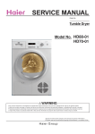
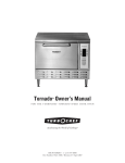
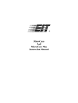
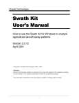
TIP 1000
Thermal Process
Controller
User’s Manual
EIT Inc.
108 Carpenter Drive
Sterling, VA 20164
Phone: 703-478-0700
Fax: 703-478-0815
Email: [email protected]
MANV0811003
TIP 1000 manual Rev. A
11/3/2008
Table of Contents
1.0 Introduction______________________________________________2
2.0 WARNINGS!_____________________________________________3
3.0 Applications ______________________________________________3
4.0 TIP 1000 Description ______________________________________4
5.0 Specifications _____________________________________________5
TIP 1000: .................................................................................................5
Additional Features:.................................................................................6
Alarm Conditions:....................................................................................6
Normal Operating Conditions:.................................................................6
6.0 Setup Guide ______________________________________________7
Typical Operation Guide: ........................................................................10
7.0 Display Interface __________________________________________10
Menu Screen Layout and Functions: .......................................................10
Error Alarm Conditions: ..........................................................................12
8.0 Quick Start Guide _________________________________________12
Set Temperature:......................................................................................12
Set Volume Flow Rate: Option 1.............................................................13
Set Air Velocity: Option 2 .......................................................................13
Start/Stop Unit: ........................................................................................13
9.0 Maintenance _____________________________________________14
Filter:........................................................................................................14
Power Cables: ..........................................................................................14
Hose: ........................................................................................................14
10.0 Customer service and support ______________________________15
11.0 Warranty _______________________________________________15
12.0 Application Notes ________________________________________16
Nozzle Temperature Profile:....................................................................16
MANV0811003
Page 1
TIP 1000 Manual Rev. A
1.0 Introduction
Congratulations on the purchase of your new TIP 1000 Thermal Process
Controller. EIT is combining its 31+ years of experience in process control and
electronics engineering with the 25+ years of heater technology experience of
Tutco-Farnam in a new Thermal Process Control system.
The days of ‘guesstimating’ and ‘retuning’ temperatures and flow rates each time
you have to run a process are a thing of the past! With your new TIP 1000, you
will be able to actually assign numbers to needed process values and be able to
dial up those numbers in a flash for future runs! You have complete control with a
digital readout of the temperature, air flow rate, and air exhaust velocity. Only
two parameters may be regulated at any one time with output temperature always
being one of them.
The TIP 1000 provides an unprecedented level of repeatability and reliability in
the thermal process control industry. Furthermore, the risk of heater burnout has
been virtually eliminated with a tight loop control system vastly improving the
life span of the heater! The typical thermocouple in the hot air stream has been
eliminated and the function replaced with a very accurate predictive algorithm
that is unaffected by errors caused by hot and cold spots as well as long exposures
to high temperatures. You can look forward to great cost savings in not having to
replace heater parts and fewer product errors due to more consistent output.
The TIP 1000 is a self contained “plug & play” system. The system contains
everything that you need. It takes just a few minutes to plug it in and connect the
heater to the control box. You do not need to specify a separate compressor or
control package.
In short, you save time and save money!
MANV0811003
Page 2
TIP 1000 Manual Rev. A
2.0 WARNINGS!
Do not touch heater when in operation or immediately after long periods of
operation!
Do not open chassis when unit is plugged in! There is risk of shock and there are
no user serviceable parts. There are ESD sensitive components inside.
Do not operate if the exhaust fan doesn’t work or is blocked! (See section 6.0)
3.0 Applications
Day to day processes in which a particular process window (output temperature
and/or flow rate) determines the quality of the product are ideally suited for the
TIP 1000. Such processes include:
• Drying, curing or activation of coatings, adhesives, resins, labels & inks
• Heat shrinking of films and covers
• Heating & Heat Staking
• Electronics Assembly Processes
• Thermal Process Laboratories
• Sterilization & Sanitizing Assembly Lines
MANV0811003
Page 3
TIP 1000 Manual Rev. A
4.0 TIP 1000 Description
The TIP 1000 is a closed-loop thermal process controller with the ability to
regulate output temperature, air velocity, and volume flow rate. Only two
parameters may be regulated at any one time with output temperature always
being one. This breakthrough is possible due to sensors throughout the system
which report back to a single controller board (Figure 1). The controller board
issues incremental commands (reduce heater power, increase air flow) to maintain
the user’s desired output values (process window). This constant adjustment and
feedback loop maintain stable repeatable process conditions.
Figure 1: Block Diagram
Another issue that the TIP 1000 addresses is potential premature heater failure
due to loss of air flow. The tightly controlled closed-loop system on TIP 1000,
ensures that the moment such an event occurs, the controller board shuts down all
power to the heater and sounds an alarm to warn the user of the event. This
dramatically increases the life of the heater and reduces the chance of making
poor products.
MANV0811003
Page 4
TIP 1000 Manual Rev. A
5.0 Specifications TIP 1000
All specifications subject to change
Specifications
Heater Power
Output Temperature Range
Flow Rate
Velocity @ nozzle
Enclosure Dimensions
Enclosure Material
Weight
Power Input, Heater (full power)
and Blower
Heater Material
Air Filter
Alarms
Repeatability
Control Accuracy
1.5 KW @ 208-240 VAC @ 6.25 amps, 50-60 Hz,
unity PF. System will operate on reduced voltage
but may be below maximum temperature
specification.
150ºF - 1150ºF (65ºC-620ºC)
4.5 – 10.0 SCFM (127-311 LPM)
20-85 ft/sec (6.1-25.7m/sec)
16.4”L x15.4”W x11.6 H” (41.7 cm x 39.1 cm x
29.5 cm)
Powder Coated Aluminum
Enclosure 35 lbs
Enclosure, heater w/5’ hose, 40 lbs
1900 VA@ 8 amps, 0.95PF
Stainless Steel
2 micron, very clean air suitable for a wide variety
of applications
Front panel audible & flashing display
> 1%
Temperature: + 3% of Full Scale
Flow rate: + 2% of Full Scale
Velocity + 5% of Full Scale
Figure 2: Achievable temperatures (°F and °C) at various flow rates
*Note: Red area is achievable temperatures at various flow rates. Maximum
values on graph will be less at lower ambient temperatures and/or lower available
heater power. Maximum flow rate will decrease as temperature goes up.
MANV0811003
Page 5
TIP 1000 Manual Rev. A
Additional features:
• Prevents heater damage with automatic heater shutoff in the event of air flow loss
• System stores current operating values on power down and restores values on
power up
• Splash resistant design
Alarm Conditions:
When the system is in an alarm condition, it will continually flash the display and
sound an audible alarm. The volume of the audible alarm can be adjusted by
turning the small disc on the alarm to a louder or quieter volume.
Parameter
Output Temperature
Volume Flow Rate
Air Velocity
Condition for Alarm
Display temperature differs from set point by
more than 20 °F
Display air flow rate differs from set point by
more than 0.5 CFM
Display air velocity differs from set point by
more than 5FPS
*Note: Audible alarm is disabled for 20 seconds after any parameter change or if
the start button is pressed.
Normal Operating Conditions:
• Ambient Operating Temperature range: 0°F to 110°F (-17°C to 43°C)
•
Humidity: up to 90% non condensing
•
Elevation: calibrated to sea level
*Note: EIT has been a pioneering leader in the process control industry for over
30 years. We have used our best practices in developing this product. Please note
that this product is not yet CE or UL certified but we plan to pursue these
approvals in the future. Please use the product at your own risk.
MANV0811003
Page 6
TIP 1000 Manual Rev. A
6.0 Setup Guide
The TIP 1000 Blower System is normally shipped in one box and the heater and
connecting hose in another box. Carefully unpack each box.
1. Attach desired plug termination to blower power cord. The green wire goes to
ground and the black and white wires are both hot, each connecting to
120VAC to make a total of 240.
Figure 3-Wire termination
2. The heater hose and a combination power/sensing cable must be attached to
the Blower Assembly. The power/sensing cable only attaches one way-do not
force the connection. Look closely at Figures 4-7
Figure 4-(Above) Heater Power/Sensing connection on left, hose connection on right
Figure 5-(Below) Heater Power/Sensing cable and Heater Hose shown connected
MANV0811003
Page 7
TIP 1000 Manual Rev. A
Figure 6-(Above) Close-up of Connector on the side of the Blower Assembly. Note
arrows showing mating notches for cable assembly
Figure 7 (Below) Close-up of Cable-Note arrows to help align cable
MANV0811003
Page 8
TIP 1000 Manual Rev. A
Figure 8-Close-up of connector on Heater Assembly. This connection has been
made at the factory prior to shipping and should not be disconnected
*Note: Do not block exhaust fan located on opposite side of display on blower
assembly
Figure 9: Menu
•
•
•
•
•
•
•
•
Turn the system on using the circuit breaker located near the power cord
input.
The menu will stabilize with numbers after a few seconds on power up.
Set desired output operating temperature using select and arrow keys.
Press Start/Stop to turn blower and heater on
Depending on selected output temperature, it may take several minutes to get
to desired temperature.
An alarm will sound if the system is not in regulation with the defined
Temperature, Airflow, and Velocity set points.
Pressing a button to change any set point will disable the alarm for 20 seconds
to allow time for the system to reach the desired value without alarming.
Also note that it will take 60 seconds for the blower to turn off after the
Start/Stop button is pressed. This is to allow the heater to cool down before
airflow is completely stopped.
MANV0811003
Page 9
TIP 1000 Manual Rev. A
Typical Operation Guide:
Select button cycling –each time the select button is pressed, the display menu
will cycle in the following sequence.
Figure 10: Menu Cycling
Only two parameters can be regulated at the same time with one always being
Output Air Temperature. You can set either of the other two to be regulated by
simply pressing the up/down arrow to choose a value on that screen. If the
Volume Flow Rate (in SCFM) is being regulated, then the Air Velocity menu
screen will have dashes for the set point value, Figure 10. If Air Velocity is being
regulated, then the Volume Flow Rate menu screen will have dashes for the set
point value. If you are on the unregulated Volume Flow Rate or Air Velocity
menu screen, then any set point adjustment on that screen will make the system
regulate to that parameter (Volume Flow Rate or Air Velocity) and disable the
other one.
7.0 Display Interface
Menu screen layout and functions:
• Main display (shows actual values)
• Set point (target value that main display is trying to reach)
MANV0811003
Page 10
TIP 1000 Manual Rev. A
•
•
•
•
Error flags
Select button
Set point adjustment arrows (Up/Down)
Start/stop button
Figure 11: Display layout
Figure 12: Output temperature screen (no error flags)
Figure 13: Volume flow rate screen (no error flags)
MANV0811003
Page 11
TIP 1000 Manual Rev. A
Figure 14: Air Velocity screen (The Air velocity is not being regulated on this
screen. This is indicated by the series of dashes on the lower left of the screen.)
Error Alarm Conditions:
In the event that a user selected value cannot be regulated, an alarm will sound
bringing immediate attention to the discrepancy. The following are the alarm flags
that will be displayed on screen.
-*Temp (Temperature out of regulation by +/- 20°F)
-*CFM (Volume flow rate out of regulation by 0.5 SCFM or more)
-*Air Vel (Air velocity out of regulation by 5 ft/s)
*Note: Alarm is disabled for 20 seconds after any set point changes
Figure 15: Temperature is out of regulation (Temp error flag is flashing)
8.0 Quick Start Guide
Terminate power cord with desired 240VAC plug. Green wire goes to ground and
the black and white wires each go to separate lines.
Set Temperature:
1 – Press select button located below the display until you cycle to Temperature
screen.
2 – Use the up and down arrows located to the right of the display to change the
target temperature. Target temperature is displayed on the lower left corner of
the display.
MANV0811003
Page 12
TIP 1000 Manual Rev. A
Set Volume Flow Rate: Option 1
1 – Press select button located below the display until you cycle to Air Flow
screen.
2 – Use the up and down arrows located to the right of the display to change the
target air flow. Target air flow is displayed on the lower left corner of the
display.
Set Air Velocity: Option 2
1 – Press select button located below the display until you cycle to Air Velocity
screen.
2 – Use the up and down arrows located to the right of the display to change the
target air velocity. Target air velocity is displayed on the lower left corner of
the display.
*Note: Option 1 and 2 cannot be set concurrently. Choose to set one or the other.
Start/Stop Unit:
Press the Start/Stand-by button to start regulation of user selected values. Press
this button again to go to Stand-by mode. The heater will shut off immediately,
but the blower will continue to run for 60 seconds.
MANV0811003
Page 13
TIP 1000 Manual Rev. A
9.0 Maintenance
Filter: Make sure air intake is not blocked or clogged by dust or other particulate
matter. The air filter should be replaced every 1000 hours of operation or sooner
if being used in a very dirty environment. Contact EIT to purchase replacement.
Manufacturer: Solberg Manufacturing
2 micron filter P/N: 10
Power Cables: Inspect for any wear or breaking of insulation and replace if
necessary. Such wear is caused by regular movement of cables against a sharp
corner and should be avoided to prevent damage or injury. Any cable rated for
230VAC is acceptable but may need to be re-terminated with the proper plug.
Contact EIT to purchase replacement.
Manufacturer: McMaster-Carr
Power Cord P/N: 7082K85
Hose: If the connecting hose from blower to heater has a hole in it, all output
values will be incorrect. Hoses with any leakage should be repaired or replaced
prior to continued use. Contact EIT to purchase replacement.
Manufacturer: McMaster-Carr
Hose P/N: 5304K45
MANV0811003
Page 14
TIP 1000 Manual Rev. A
10.0 Customer service and support
For service and support, call the following number:
Phone: 703-478-0700
Fax: 703-478-0815
Email: [email protected]
Our normal hours are 9-4:30 EST.
11.0 Warranty
EIT (Seller) warrants to Purchaser that the goods manufactured and sold by it will be free
from defects in materials for a period of 12 months from the day of delivery of the goods.
Seller’s liability under this warranty shall be limited, at the Seller’s elections, to the
purchase price or the replacement or the repair of such defective goods. No claim under
this warranty shall be valid unless made in writing to the Seller within 12 months of the
delivery of the goods sold hereunder, nor will any claim be allowed on goods which have
been processed or altered in any manner (normal inspection procedures excepted). Seller
shall have a reasonable opportunity to examine all goods claimed to be defective.
Transportation charges for the return of each defective goods to the original point of
delivery or such other place designated by the Seller shall be paid by the Purchaser who
shall be credited by Seller for such reasonable transportation cost. This warranty
supersedes and is in lieu of any other warranty, expressed or implied, or no agreement, or
understanding varying, or extending this warranty will be binding upon Seller unless in
writing, signed by a duly authorized officer of Seller.
MANV0811003
Page 15
TIP 1000 Manual Rev. A
12.0 Application Notes
Nozzle Temperature Profile:
Below is the temperature profile across the heater nozzle at various distances.
Individual heater profiles may vary slightly across the x-axis due to internal
mechanical alignment. The information below is intended purely as reference
material.
Graph 1: Nozzle Temperature Profile
TIP 1000 Nozzle Temperature Profile at 5.5 SCFM, 550 °F Set Point, 75°F Room Temp
600
550
500
450
Temperature (°F)
400
350
Nozzle Distance = 0"
Nozzle Distance = 1"
Nozzle Distance = 2"
300
250
200
150
100
50
0
-1.2
-1
-0.8
-0.6
-0.4
-0.2
0
0.2
0.4
0.6
0.8
1
1.2
Position from center of nozzle (inches)
MANV0811003
Page 16
TIP 1000 Manual Rev. A