1
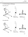
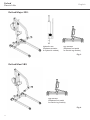
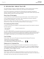
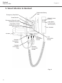
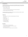
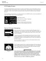
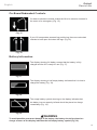
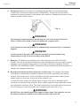
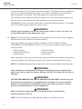
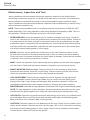
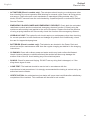
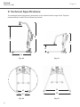
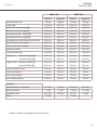
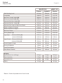
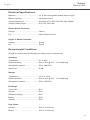
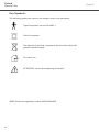
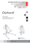
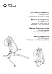
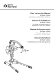
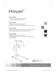
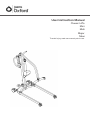
User Instruction Manual
Classic Lifts
Mini
Midi
Major
Maxi
To avoid injury, read user manual prior to use.
Oxford
Classic Lifts
®
English
Contents
1. Oxford Classic Lift Range................................................................................................... 3
2. Introduction: About Your Lift................................................................................................ 5
3. Assembly & Commissioning Instructions............................................................................ 6
4. Safety Precautions........................................................................................................... 10
5. Smart™ Monitor & Handset.............................................................................................. 12
6.
Operating Instructions...................................................................................................... 16
7. Charging Instructions (Electric models only).................................................................... 19
8. Maintenance Schedule & Daily Check List....................................................................... 21
9. Technical Specifications................................................................................................... 24
10. Servicing, Repairs, Inspections and Testing..................................................................... 29
2
Oxford
Classic Lifts
®
English
1. Oxford Classic Lift Range
Oxford Mini 140:
Hydraulic ram
(Replaces actuator
on hydraulic models)
Leg actuator
(Replaces foot pedal
on electric leg models)
Fig. 1
Oxford Midi 180:
Hydraulic ram
(Replaces actuator
on hydraulic models)
Leg actuator
(Replaces foot pedal
on electric leg models)
Fig. 2
3
Oxford
Classic Lifts
®
English
Oxford Major 200:
Hydraulic ram
(Replaces actuator
on hydraulic models)
Leg actuator
(Replaces foot pedal
on electric leg models)
Fig. 3
Oxford Maxi 180:
Leg actuator
(Replaces foot pedal
on electric leg models)
Fig. 4
4
Oxford
Classic Lifts
®
English
2. Introduction: About Your Lift
The Oxford Classic Lift range is available with hydraulic or electric powered options with the
exception of the Maxi 180 which is electric only. This manual covers both options.
Each lift is fully assembled, load tested and certified before being partially dismantled for
packing. The packing consists of a strong, purpose built carton and is used for both export and
domestic markets to ensure the safe arrival of the lift.
Recycling of Packaging:
In an effort to reduce levels of waste and environmental impact, Joerns Healthcare operate
a free of charge recycling service in the UK. This is specifically for the foam inserts that
accompany the lift packaging - inside of the carton.
When you are ready to return the foam inserts, simply present them to the Joerns Delivery
Service Driver on their next visit and they will return them to us for recycling.
Accompanying Documents:
A number of documents are supplied in a wallet packed with each lift and should be retained
for future reference.
• Test Certificate
• User Manual
• Dealer Guarantee Card
The TEST CERTIFICATE is an important document and is required for your insurance
records. It is valid for 6 months and once expired, the lift should be inspected and serviced for
the following six month period. Servicing and periodic LOLER testing can be carried out by
your supplier. Please ensure your lift is included in their maintenance schedule.
The CE Mark:
Oxford Classic Lifts carry the CE mark and comply with the following EC directives:
• Medical Device Directive (93/42/EEC)
• EMC Directive (89/336/EEC) (Electrics only)
• Low Voltage Directive (73/23/EEC) (Electrics only)
Statement of Intended Use:
The intended use of this lifting device is to transfer an individual from one resting surface to
another (such as a bed to a wheelchair). Moving a person in a sling over extended distances
is not recommended. Oxford Classic Lifts are suitable for patients in the SITTING, SITTING/
RECUMBENT and RECUMBENT positions.
Expected Service Life:
Oxford Classic mobile lifts are designed and tested for a minimum service life of seven (7)
years, subject to the use and maintenance procedures stated in this manual. Use other than in
accordance with these instructions may compromise service life.
5
Oxford
Classic Lifts
®
English
3. Assembly and Commissioning Instructions
Place the carton in a clear working area and open carefully. The carton contains:
• Main wheeled chassis
• Mast and boom assembly
• Battery pack (electric lifts only)
• Wallet containing documents
• Battery charger (electric lifts only)
• Hand control (electric lifts only)
1. Remove all the parts from the carton and place on the floor, taking care to protect the
finish from damage.
WARNING
Some of the parts are heavy and will need to be lifted with care. You may need
assistance with the heavier assemblies.
2. Apply the rear castor brakes by pushing the brake levers (Fig. 5) downwards.
3. Fit the mast assembly to the chassis. The mast is located into the rectangular socket on
the top centre of the chassis. (Fig. 5 - manual leg model shown).
WARNING
Avoid trapping fingers. Keep fingers away from the end of the mast when inserting
into the socket.
Mast Assembly
Rectangular Socket
Brake Lever
Brake Lever
Mast Locking Knob
Fig. 5
4. When the mast is fully engaged within the socket, turn the mast locking knob (Fig. 5)
clockwise, until fully tightened.
6
WARNING
Full engagement of the mast is indicated by the label on the side of the mast.
Oxford
Classic Lifts
®
English
5. Electric Leg Operation: There is some minor assembly required in order to connect the
leg actuator to the leg adjustment mechanism. Gently swing the actuator into place over the
leg pivot bracket ensuring the corresponding holes are in alignment. Insert the clevis pin,
ensuring the plastic wear washers remain in place. To finish, fit the spring clip through the
hole in the clevis pin and confirm secure attachment.
Spring clip
Clevis pin
Fig. 6
Foot Pedal Leg Operation: If your lift is fitted with foot pedal operated legs, release the
brakes and confirm they open and close satisfactorily by operating the push pedals (Fig. 7).
Hold onto the push handle for stability.
Push Pedal (Open)
Push Pedal (Close)
Fig. 7
7
Oxford
Classic Lifts
®
English
Electric Models Only:
6. Clip the battery onto the control box and ensure the red emergency stop button, located
on the controller is in the out (ON) position by turning clockwise (Fig. 8).
Emergency Stop
Button
Redundant Control
(Emergency Lower)
Electric Leg
Redundant Control
(Legs Close)
Electric Leg
Redundant Control
(Legs Open)
(Model dependent)
(Model dependent)
Fig. 8
7. Push the UP and DOWN buttons on the hand control and confirm the boom will raise and
lower accordingly (Fig. 9).
NOTE: If your lift incorporates electric leg operation, confirm the legs open and close by
pushing the OPEN and CLOSE buttons on the hand control.
UP (Raise)
DOWN (Lower)
Legs Open
Legs Close
(Model dependent)
(Model dependent)
Fig. 9
8. Prior to initial use, the service counter must be zeroed by an authorised dealer.
9. The lift is now ready for use.
8
Oxford
Classic Lifts
®
English
Hydraulic Models Only:
6. Close the hydraulic unit release valve (Fig. 10) by turning the knurled black knob on the
unit fully clockwise.
Pump Handle
Release Valve Knob
Fig. 10
NOTE: The release valve requires only minimal tightening to operate and should only be
closed finger tight.
WARNING
DO NOT apply excessive force to the release valve knob as this will result in
damage to the valve.
7. Pump the handle (Fig. 10) of the hydraulic unit and confirm the ram raises the boom.
8. Open the release valve fully anti-clockwise and check the boom descends.
NOTE: An unloaded boom will not come down under its own weight, it will be necessary
to apply some pressure to the boom before it will descend.
WARNING
The release valve is fully open and encounters a positive end stop in less than two
full turns of the knob. DO NOT force the valve past the end stop as this will result in
damage to the valve.
9.
Close the release valve by turning the knurled black knob clockwise.
10. The lift is now ready for use.
9
Oxford
Classic Lifts
®
English
4. Safety Precautions
Please read and follow the safety precautions listed below. The operation and use of Oxford
patient lifts is simple and straightforward. Following these few basic safety precautions will
make lifting operations easy and trouble free.
WARNING
• ALWAYS plan your lifting operations before commencing.
• ALWAYS carry out the DAILY CHECK LIST before using the lift.
• ALWAYS familiarise yourself with the operating control and safety features of a lift before lifting a patient.
• DO NOT use a sling unless it is recommended for use with the lift.
• ALWAYS check the sling is suitable for the particular patient and is of the correct size and capacity.
• NEVER use a sling which is frayed or damaged.
• ALWAYS fit the sling according to the instructions provided (user instructions).
• ALWAYS check the safe working load of the lift is suitable for the weight of the patient.
• ALWAYS carry out lifting according to the instructions in the user manual.
• NEVER disconnect or bypass a control or safety feature because it seems easier to operate the lift.
•
NEVER force an operating or safety control. All controls are easy to use and do not require excessive force to operate. If a control is not working easily there will be a reason. Forcing will only strain or damage the lift and may compromise safety. If in doubt, contact your authorised Oxford Service Provider or Joerns Healthcare.
• DO NOT lift a patient with the castor brakes on.
• DO NOT attempt to manoeuvre the lift by pushing on the mast, boom or patient.
• ALWAYS manoeuvre the lift using the handles provided. DO NOT attempt to apply additional side force to the boom or legs of the lift in order to manoeuvre the product.
• ALWAYS lower the patient to the lowest comfortable position before transfers.
• DO NOT push a loaded lift at speeds which exceed a slow walking pace
(3 kilometers/hour 0.8 metres/second).
• DO NOT push the lift over uneven or rough ground, particularly if loaded.
10
Oxford
Classic Lifts
®
English
WARNING
• DO NOT attempt to push or pull a loaded lift over a floor obstruction which the castors are unable to ride over easily.
• DO NOT bump the lift down steps, loaded or unloaded.
• DO NOT attempt to negotiate a loaded lift on a slope which exceeds 1:12 (approximately 5 degrees). Joerns Healthcare recommend a second helper is present when moving a patient on a slope.
• DO NOT park a loaded lift on ANY sloping surface.
• DO NOT use electric lifts in a shower.
• DO NOT charge an electric lift in a bathroom or shower room.
• DO NOT lift a patient unless you are trained and competent to do so.
• Your lift is for patient lifting. DO NOT use it, or allow it to be used, for any other purpose.
• The Oxford Classic Range is not intended for continuous use/storage in condensing humid conditions.
11
Oxford
Classic Lifts
®
English
5. Smart Monitor & Handset
Emergency Stop Button
Detachable Battery
Pack
Smart Monitor
Raise & Lower
Buttons
Emergency Raise & Lower
Redundant Controls
Legs Open /
Close Buttons
Legs Open / Close
Redundant Controls
(Model dependent)
(Model dependent)
Handset
Actuator
Handset
Connection
Socket
Handset
Connection
Plug
Leg
Actuator
Connection
Socket
LCD
Information
Screen
Actuator
Connection
Socket
Fig. 11
12
Oxford
Classic Lifts
®
English
Intended Use:
The Oxford Smart Monitor is a control system for Oxford Mobile Hoists. The Smart Monitor
stores useful servicing information about the hoist that can be recalled when required. This
servicing information includes:
• Number of patient lift cycles
• Total work done by actuator
• Number of lift overloads (attempted lifts above the safe working load)
• Number of days since last service interval
The Oxford Smart Monitor contains a microprocessor inside making it possible to read out
service data via the on-board LCD screen.
Features:
• Data collection in the control box with data display via LCD screen
• Work counter
• Intelligent cycle counter
• Service indicator
• Service interval indicator
• Overload information
• 3 step battery indicator
Benefits:
• Improved safety for both patient and carer
• Accurate service data available at the touch of a button
• Optimised product life time
• Ease of maintenance for engineers and service technicians
13
Oxford
Classic Lifts
®
English
LCD Display Screen:
The Oxford Smart Monitor has the option to read out information via the LCD display screen. It
is possible to read out total lifting cycles, total work done, overloads and number of days since
last service, which can be used to quickly and easily evaluate the condition of the lift actuator
(Fig. 12).
This information is accessed by a ½ second press on the ‘RAISE’ button on the User handset or
redundant ‘RAISE’ button on the Smart Monitor.
Total Lifting Cycles
Total Work Done (Amps * Seconds)
Number of Overloads
Fig. 12
Number of Days (since last service) /
Number of Days (between services)
Service & Usage Information:
When it is time for a service, the service symbol will appear on the
display (Fig. 13). In addition, when the user handset is activated, the
Smart Monitor will give an audible signal giving notice to users that a
service is required.
Fig. 13
The service symbol will be displayed each time the raise or lower
keys are depressed on the user handset. When the service symbol
is displayed, contact your authorised service provider immediately to
arrange a service.
You may continue to use your lift for a short period of time until a
service has been carried out.
If the lift stops because of an overload (an attempt to lift more than the
safe working load) the overload symbol will appear on the LCD display
(Fig. 14) and the lift will cease to operate until the additional load
(above the SWL) has been removed.
Fig. 14
14
WARNING
If the LCD display screen on your Smart Monitor has recorded
an overload, Joerns Healthcare recommend that ALL routine daily
checks are carried out on the lift prior to further use (for a list
of daily checks, please refer to your lift user manual). Joerns
Healthcare also recommend that you contact your authorised
Oxford service provider for additional guidance.
Oxford
Classic Lifts
®
English
On-Board Redundant Controls:
On-board redundant controls enable the lift to be raised or lowered in
the event of an emergency (Fig. 15).
Fig. 15
If your lift incorporates powered leg positioning, there are redundant
controls to both open and close the legs. (Fig 16).
Fig. 16
Battery Information:
The display showing full battery means that the battery is fully
charged and the lift is ready for use (Fig. 17).
Fig. 17
The display showing a half empty battery indicates that it is time to
charge the battery (Fig. 18).
Fig. 18
The empty battery symbol showing on the display indicates that
the battery has no capacity left and should be placed on charge
immediately (Fig. 19).
Fig. 19
WARNING
To avoid possible permanent damage to the battery, the battery should be placed on
charge as soon as the display indicates the half empty battery symbol (Fig. 18).
15
Oxford
Classic Lifts
®
English
6. Operating Instructions
1. Leg adjustment: The legs on Oxford Classic lifts can be opened to enable access around
armchairs, wheelchairs and other furniture. For transferring and negotiating narrow doorways and passages, the lift legs should be in the closed position.
Electric Leg Operation: Simply press the appropriate button on the hand control in order
to open or close the legs. You may also use the redundant control soft keys located on the
front of the control box above the LCD display screen.
Foot Pedal Leg Operation: Simply operate the push-pads, located at the lower/rear
of the mast. To open the legs, simply depress the LEFT push-pad. To close the legs,
depress the RIGHT push-pad.
In either case, the adjustment can be carried out with the patient in the lift.
2. Castors and braking: The lift has two braked castors which can be applied for parking.
When lifting, the castors should be left free and unbraked. The lift will then be able to
move to its centre of gravity. If the brakes are applied, it is the patient that will swing to the
centre of gravity and this may prove disconcerting and uncomfortable.
3. Direction of travel (Forward motion): The Classic
range of mobile lifts are designed to be pushed
forwards using the integrated push-handle.
Fig. 20
4. Straight line steering (where fitted): One of the rear castors is fitted with a straight line
steering device. To engage the device simply swing the ‘U’ shaped bar over the rear castor. The device will automatically engage as you move off.
5. Raising and lowering the boom (electric models): The movement of the boom is
achieved by a powerful electric actuator which is controlled by a simple hand control unit.
The hand control has two buttons with directional arrows RAISE and LOWER. The actuator
stops automatically at the limit of travel in both directions. The hand control plugs into a
socket at the base of the control box. There is a magnetic backing to the hand control
which allows it to be “parked” on the mast or boom when not in use.
6. Emergency stop (Electric only): The red emergency stop button is located on the control
box and is activated by pressing in. This will cut all power to the lift and can only be reset
by twisting the button clockwise and releasing.
7. Redundant controls: All Oxford Classic Lifts are fitted with raise and lower buttons on the
control box. These are located underneath the emergency stop button and can be used to
lower/raise the patient should the hand control fail.
16
Oxford
Classic Lifts
®
English
8. Emergency lower: In the case of a complete electrical failure the electrical actuator
is fitted with a mechanical lowering device (RED BOSS). The device must be twisted
clockwise by hand to operate. A slow decent will commence. Repeat this process until the
patient has been safely lowered.
Fig. 21
WARNING
The emergency lowering device should only be used in the event of electrical failure. It must not be used to lower the patient on a regular basis.
WARNING
If this feature is used, the lift MUST be subsequently checked out by a competent engineer.
WARNING
Continued use of the hoist after using the emergency descent feature may
compromise the duty of care and safety of the patient.
9. Batteries: The batteries are protected from deep discharge by a LOW VOLTAGE
ALARM. This will sound when the batteries need recharging and the hand control is being
operated. It will not sound independently of the hand control being operated. DO NOT
IGNORE THIS WARNING ALARM. Complete the lifting operation and place the battery on
charge (see charging instructions).
10. Raising and lowering the boom (hydraulic models only): The raising and lowering
of the boom is achieved by a powerful hydraulic ram which is operated by two simple
controls. The release valve, which is identified by a black knurled knob, and the pump
handle which is a long lever on the side of the hydraulic unit.
To raise the boom, ensure the release valve is closed. The valve is closed by gently
turning the knurled knob fully clockwise. When closed, pump the long handle with smooth
even strokes for maximum effect. The handle strokes from an upright position through an
arc of 90 degrees. Leave the handle in the upright position when not in use.
WARNING
DO NOT force the handle beyond the upper or lower stops. The hydraulic unit can
be rotated to allow the handle to be used from either side of the lift.
17
Oxford
Classic Lifts
®
English
To lower the boom, turn the release valve anti-clockwise. The release valve is progressive,
the more it is opened the faster the descent. The valve is restricted so even when fully
open the descent is controlled. This facility allows for a “hands free” descent.
If the release valve is opened a fraction (a quarter turn) a very slow speed of descent will
allow the carer to work “hands free” while assisting or comforting the patient.
REMEMBER to close the release valve before commencing lifting operations. The release
valve only requires gentle pressure to open or close.
DO NOT apply excessive force to the release valve, either to close or to open. It is
not necessary and will only damage the valve.
WARNING
11.Slings: The selected sling is attached to the spreader bar hooks. Each sling is supplied
with instructions which should be followed carefully.
The Oxford Classic Lift range is suitable for patients in the SITTING, SITTING/
RECUMBENT and RECUMBENT positions. The core slings suitable for these lifts are
listed as follows:
• Oxford Quickfit
• Oxford Quickfit Deluxe
• Oxford Access
• Oxford Full Back
• Oxford Long Seat
• Oxford Silkfit
When selecting a sling from the Oxford range, be sure to assess the suitability of the type of
sling for the patient to be lifted by conducting a thorough risk assessment prior to lifting.
NOTE: For detailed fitting instructions, please refer to the user guide supplied with each sling.
WARNING
Joerns Healthcare recommends that slings be checked regularly and particularly
before each use for signs of fraying or damage. DO NOT use slings that are worn or
damaged.
OXFORD RECOMMENDS THE USE OF GENUINE OXFORD PARTS. Oxford sling and
lift products are designed to be compatible with one another. For country specific
guidance on sling use and compatibility, please refer to the sling label or contact
your local market distributor or Joerns Healthcare.
Refer to maximum weight capacity of lift. Sling capacity is limited by the
maximum capacity of the lift.
WARNING
WARNING
NOTE: For further guidance on sling selection, please visit www.joerns.co.uk
18
Oxford
Classic Lifts
®
English
7. Charging Instructions (Electric Models Only)
The batteries are located in the power pack and are charged through two contacts on the
base. When the power pack needs charging it is removed from the lift and fitted to a charging
unit. Joerns Healthcare recommend an additional power pack is purchased, so that one pack
can be on charge at all times.
1.
Remove the power pack from the lift. The pack is retained by a simple latch at the top of
the pack. Lift the latch and the power pack will be released.
2. Fit the power pack to the charging unit. The location and latching of the power pack to
the charger is the same system as used on the lift.
3. Plug the charger mains plug into a suitable mains outlet and switch the mains supply ON.
4. Charging is automatic and will fully charge the batteries over a period of eight to twelve
hours. Note: Even if the charger is left plugged in for extended periods it will not allow
the batteries to “overcharge”.
a) Green Light - Indicates main power is on.
b) Yellow Light - Indicates battery is charging.
c) Battery will be fully charged when yellow light goes off.
NOTE: It is recommended that the battery be charged immediately upon receipt.
5. To return the lift to service, switch OFF the mains supply and remove the power pack
from the charger. Fit the power pack to the lift and make sure the latch holding the pack
in place is fully engaged.
The charging of Oxford electric lifts is simple and straightforward, but it is important to
follow the charging instructions closely. Please pay particular attention to the following
points, they will help you avoid problems with discharged batteries.
To avoid possible permanent damage to the battery, the battery should be placed
on charge as soon as the display indicates the half empty battery symbol (Fig. 18,
page 15).
KEEP the batteries fully charged. Place the power pack on charge whenever it is not
in use. If it is more convenient to do so, place on charge every night. The charger
will not allow the batteries to “overcharge”.
WARNING
19
Oxford
Classic Lifts
®
20
English
WARNING
NEVER run the batteries completely flat. As soon as the audible warning sounds,
complete the lifting operation in progress and place on charge.
NEVER store the power pack for long periods without regular charging throughout
the storage period.
ALWAYS make sure the mains power to the charger is switched off before
connecting or disconnecting the power pack.
NEVER leave the power pack plugged in to the charger with the mains power off.
ALWAYS check Battery Charge Indicator (LCD) screen.
Batteries NOT to be opened by unauthorised personnel. (Contact your distributor
for warranty and repairs).
DO NOT touch battery/charger terminals.
DO NOT leave charger switched on with battery disconnected.
Oxford
Classic Lifts
®
English
8. Maintenance Schedule and Daily Check List
All Oxford products are designed for minimum maintenance, however some safety checks and
procedures are required. A schedule of DAILY tasks are detailed below.
Daily checks and a bi-annual service, inspection and test will ensure your lift is kept in
optimum safe working condition. A list of spare parts is available upon request.
NOTE: The LOAD TEST and CERTIFICATION should only be carried out by qualified
personnel or an authorised service dealer.
Daily Check List:
Joerns Healthcare Ltd strongly recommend the following checks are carried out on a daily basis
and before using the lift.
• ENSURE the lift moves freely on its castors.
• ENSURE the spreader bar is free to rotate and swing. Check the spreader bar is firmly
attached to the boom.
• EXAMINE the sling hooks on the spreader bar and side suspenders for excessive wear. If
in doubt - DO NOT use.
• ENSURE the sling retaining disks on the spreader bar are fitted and function as intended.
• ENSURE the legs open and close correctly.
• Operate the hand control or the hydraulic unit to CONFIRM the boom raises and lowers
satisfactorily.
• CONFIRM the lift is not giving a low battery alarm when the hand control is operated
(electric lifts only). If the alarm sounds, DO NOT use and place the battery on charge
immediately.
• On electric powered lifts CHECK the operation of the emergency stop button.
• On hydraulically operated lifts CHECK for hydraulic fluid leakage. Any leakage should be
reported to a service engineer immediately and the lift should not be used until it has been
checked out.
• On lifts with detachable masts MAKE SURE the mast is fully engaged and the locking knob
is fully tightened.
• EXAMINE slings for fraying or other damage. DO NOT use any sling if damaged or if the
sling shows signs of wear.
• EXAMINE all fixings and fasteners and ensure they are secure prior to use.
21
Oxford
Classic Lifts
®
English
Maintenance, Inspection and Test:
Joerns Healthcare Ltd recommend a thorough inspection and test of the Oxford Mobile
Hoist lifting accessories, slings etc. is carried out at least every six months. The examination
and test should be conducted according to the recommendations and procedures below.
Joerns Healthcare recommend maintenance, inspection and certified testing is carried out by
authorised service dealers only.
NOTE: These recommendations are in compliance with the requirements of 1998 No. 2307
Health and Safety: The Lifting Operations and Lifting Equipment Regulations 1998. This is a
UK regulation. Outside the UK please check your local requirements.
• SPREADER BAR: Check the spreader bar for freedom of rotation and swing. Check for
wear on the central pivot. Check for presence and condition of the wear washer. Check for
firm attachment to the boom. Inspect for excessive wear on the sling hooks and any side
suspenders used in conjunction with the spreader bar. Check that the sling retaining disks
are fitted and function as intended. Lubricate the main suspension point and central pivot
with a light mineral based grease or silicon spray.
• BOOM: Check for secure attachment of the boom to the mast. Make sure there is only
minimal side movement of the boom and the boom is free to rotate on the boom bearing.
Check the boom is centered and does not exhibit signs of damage. Check that the actuator
or hydraulic unit mounting on the boom is secure.
• MAST: Check the operation of the mast locking device. Make sure the mast fully engages
into the socket. Check that the bottom actuator or hydraulic unit mounting is secure.
• SMART MONITOR (Electric only): Check the function of the emergency stop button.
Inspect the hand control socket for correct fitting. Check functioning of the hand control.
Check the redundant controls and confirm they operate as intended.
• LEG ADJUSTMENT: Check the leg linkages are secure. Operate the leg adjustment
pedals or handset controls (electric leg models only) to confirm smooth opening and
closing of the legs. If leg linkages are damaged, they should be replaced. Confirm the
leg adjustment mechanism locks/ locates correctly in all open and closed positions.
MAINTENANCE: Lubricate the leg adjustment mechanism with a light mineral based grease.
NOTE: To ease application of the lubrication, the mast should be removed from the cross
member and the grease applied from inside the mast socket (foot pedal operation only).
• LEG PIVOTS: Check the leg pivots are secure and the legs pivot freely. Any stiffness must
be investigated. Strip out the leg pivots and lubricate with a light mineral based grease.
Make sure there is no excessive play in the leg pivots.
• CASTORS: Check all castors for firm attachment to the legs. Check for free rotation of the
castor and the wheels. Remove any build up of threads, hair or fluff. Lubricate if necessary
with a light mineral based grease or silicon spray. Check correct operation of the brakes.
Confirm all four castors sit firmly on the ground.
22
Oxford
Classic Lifts
®
English
• ACTUATORS (Electric models only): The actuators should require no maintenance other
than checking for correct operation and listening for unusual noise. Ensure all fixing points
are secure. Confirm the anti-crush mechanism is operational (lifting actuator only). If in
doubt, DO NOT use and have the unit checked by a qualified person or authorised Oxford
Service Provider.
• EMERGENCY RAISE/LOWER AND EMERGENCY DESCENT: Check both the redundant
raise/lower controls and the mechanical emergency descent function (if fitted) using the
maximum safe working load applied to the end of the boom. Please note that the practice
of using a spring balance will not correctly check the function of the emergency descent.
• HYDRAULIC UNIT: The hydraulic unit should require no maintenance other than checking
for correct operation in both directions and leakage of hydraulic fluid. Additionally, check
the ram for trapped air/sponginess.
• BATTERIES (Electric models only): The batteries are located in the Power Pack and
should not require maintenance other than the regular charging as detailed in the charging
instructions.
• CLEANING: Clean with ordinary soap and water and/or any hard surface disinfectant.
Harsh chemical cleaners or abrasives should be avoided as these may damage the
surface finish of the lift. Avoid wetting any of the electrical parts.
• SLINGS: Check for wear and fraying. DO NOT use any sling that is damaged, or if the
sling shows signs of wear.
• LOAD TEST: The load test should be carried out in accordance with the
manufacturer’s test procedures. It is strongly recommended the testing is carried out by an
authorised service dealer.
• CERTIFICATION: An authorised service dealer will issue a test certificate after satisfactory
completion of the load test. This certificate will be valid for six months.
23
Oxford
Classic Lifts
®
English
9. Technical Specifications
The drawings below highlight key dimensions for the Oxford Classic range of lifts. Physical
measurements for each lift are referenced overleaf.
B
D
C
E
A
Fig. 22
Fig. 23
F
K
J
Fig. 24
24
H
G
Fig. 25
Oxford
Classic Lifts
®
English
MINI 140
Electric
MIDI 180
Hydraulic
Electric
Hydraulic
Safe Working Load
140 kgs
140 kgs
180 kgs
180 kgs
Length (A)
1175 mm
1175 mm
1225 mm
1225 mm
Maximum Overall Height (B)
1730 mm
1730 mm
1840 mm
1840 mm
Minimum Overall Height (C)
1230 mm
1230 mm
1240 mm
1240 mm
Spreader Bar Max. Height (D)
1545 mm
1560 mm
1660 mm
1630 mm
Spreader Bar Min. Height (E)
530 mm
540 mm
525 mm
500 mm
Spreader Bar Height at Maximum Reach
1000 mm
1000 mm
1060 mm
1060 mm
Reach at Maximum Height *
420 mm
370 mm
420 mm
470 mm
Reach at Minimum Height *
400 mm
420 mm
440 mm
460 mm
Maximum Reach
565 mm
565 mm
656 mm
656 mm
Turning Radius (F)
1150 mm
1150 mm
1235 mm
1235 mm
(External Width) (G)
1060 mm
1060 mm
1170 mm
1170 mm
(Internal Width) (H)
1000 mm
1000 mm
1070 mm
1070 mm
Legs Closed (External Width) (J)
600 mm
600 mm
600 mm
600 mm
(Internal Width) (K)
Legs Open 540 mm
540 mm
540 mm
540 mm
Overall Height of Legs
100 mm
100 mm
100 mm
100 mm
Ground Clearance
25 mm
25 mm
25 mm
25 mm
Front Twin Castors
75 mm
75 mm
75 mm
75 mm
Rear Braked Castors
100 mm
100 mm
100 mm
100 mm
Weights:
Mast & Boom Inc. all fixings
17.5 kgs
17.5 kgs
20.5 kgs
20.5 kgs
Base Assembly
11 kgs
11 kgs
11.5 kgs
11.5 kgs
Assembled Unit
28.5 kgs
28.5 kgs
32 kgs
32 kgs
2.9 kgs
-
2.9 kgs
-
Battery
* Reach = Centre of spreader bar to front of mast
25
Oxford
Classic Lifts
®
English
MAJOR 200
Electric
Safe Working Load
MAXI 180
Hydraulic
Electric
200 kgs
200 kgs
180 kgs
Length (A)
1300 mm
1300 mm
1315 mm
Maximum Overall Height (B)
1930 mm
1930 mm
2150 mm
Minimum Overall Height (C)
1380 mm
1380 mm
1560 mm
Spreader Bar Max. Height (D)
1715 mm
1705 mm
1970 mm
Spreader Bar Min. Height (E)
565 mm
525 mm
780 mm
Spreader Bar Height at Maximum Reach
1200 mm
1200 mm
1420 mm
Reach at Maximum Height *
610 mm
620 mm
550 mm
Reach at Minimum Height *
515 mm
510 mm
540 mm
Maximum Reach
720 mm
720 mm
730 mm
Turning Radius (F)
1310 mm
1310 mm
1310 mm
(External Width) (G)
1230 mm
1230 mm
1230 mm
Legs Open (Internal Width) (H)
1140 mm
1140 mm
1140 mm
Legs Closed (External Width) (J)
660 mm
660 mm
660 mm
(Internal Width) (K)
580 mm
580 mm
580 mm
Overall Height of Legs
100 mm
100 mm
100 mm
Ground Clearance
15 mm
15 mm
15 mm
Front Twin Castors
75 mm
75 mm
75 mm
Rear Braked Castors
100 mm
100 mm
100 mm
Mast & Boom Inc. all fixings
23 kgs
23 kgs
24 kgs
Base Assembly
19 kgs
19 kgs
19 kgs
Assembled Unit
42 kgs
42 kgs
43 kgs
Battery
2.9 kgs
-
2.9 kgs
Weights:
* Reach = Centre of spreader bar to front of mast
26
Oxford
Classic Lifts
®
English
Electrical Specifications:
Batteries................................................. 2 x 12 Volt rechargeable sealed lead acid type
Battery Capacity.................................... 2.9 Ampere hours
Charger Rated Input.............................. 100-240V AC/24 VDC 50/60 Hz. Max 400MA
Charger Rated Output........................... 29.5 VDC. Max 19W
Electric Shock Protection:
Charger.................................................. Class II
Lift.......................................................... Internal Power Source
Degree of Shock Protection:
Charger.................................................. Type B
Lift.......................................................... Type B
Environmental Conditions:
Outside this environment functionality and safety may be compromised.
Operating:
Temperature .......................................... 5°C to 40°C
Relative humidity.................................... 20% to 90% @ 30°C - not condensing
Atmospheric pressure............................ 700 to 1060 hPa
Noise level.............................................. 55 dB
Storage:
Temperature........................................... -10°C to +50°C
Relative humidity.................................... 20% to 90% @ 30°C - not condensing
Atmospheric pressure............................ 700 to 1060 hPa
IP Ratings:
Control Box ........................................... IPX4
Actuator.................................................. IPX4
Off Board Charger ................................. IPX5
Battery ................................................... IPX5
Handset ................................................. IPX5
Duty Cycles:
Actuator.................................................. 10% (2 min/18 min)
Battery ................................................... 10% (2 min/18 min)
27
Oxford
Classic Lifts
®
English
Key Symbols:
The following symbols are used on the charger, control unit and battery:
Type B equipment, as per EN 60601-1
Class 2 equipment
The disposal of electrical components should not be mixed with
general household waste
For indoor use
ATTENTION, consult accompanying documents.
WEEE Producers registration number WEE/GG0464RZ
28
Oxford
Classic Lifts
®
English
10. Servicing, Repairs, Inspections and Testing
Joerns Healthcare has an established network of authorised distributors and service agents who
will be pleased to handle all of your purchasing, warranty, repair and maintenance enquiries. It
is recommended that our products are commissioned by your authorised distributor or service
agent.
The distributor or service agent operates the warranty programme, so it is important to keep
a record of their name, address and telephone number so they can be contacted should any
problem arise. If you are in any doubt as to where your lift was purchased, Joerns Healthcare
can trace the supplier if you quote the serial number of the lift.
All warranty claims are subject to the correct use and maintenance in accordance with the user
instruction manual provided with each lift. Damage caused by use in unsuitable environmental
conditions or failure to maintain the product in accordance with user and service instructions is
not covered. Your statutory rights remain unaffected.
REMEMBER: Contact your authorised distributor or service agent for purchases, repairs,
servicing and certified maintenance.
Your distributor:
29
Packing Check List:
o User Manual
o Charger with Stand & Lead
o Test Certificate
o Base Assembly
o Dealer Guarantee Card
o Mast & Boom Assembly
o User Handset
o Foam Packaging Inserts
o Battery Pack
o________________________
Checked for you by:
________________________________
Joerns Healthcare Ltd
Drakes Broughton Business Park
Worcester Road, Drakes Broughton
Pershore, Worcestershire
WR10 2AG, United Kingdom
(T) +44 (0)844 811 1156
(F) +44 (0)844 811 1157
[email protected]
© 2014, Joerns Healthcare • 6110142 Rev C • DCO14-0003