1
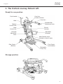
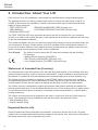
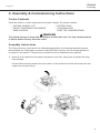
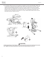
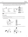
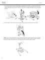
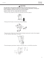
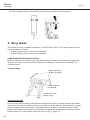
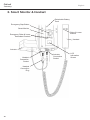
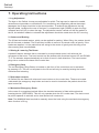
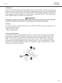
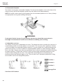
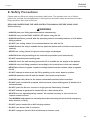
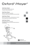
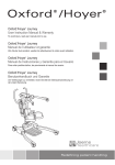
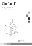
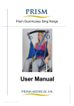
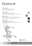
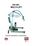
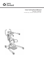
User Instruction Manual
Oxford Journey
®
To avoid injury, read user manual prior to use.
Oxford
Journey
®
English
Contents
1. The Oxford Journey Patient Lift......................................................................................3
2. Introduction: About Your Lift............................................................................................4
3. Assembly & Commissioning Instructions........................................................................5
4. Sling Guide....................................................................................................................10
5. Lifting With Your Oxford Journey...................................................................................12
6. Smart Monitor & Handset..............................................................................................14
7. Operating Instructions...................................................................................................18
8. Safety Precautions........................................................................................................21
9. Charging Instructions....................................................................................................23
10. Maintenance Schedule & Daily Check List...................................................................25
11. Technical Specifications................................................................................................27
12. Warranty........................................................................................................................30
2
Oxford
Journey
®
English
1. The Oxford Journey Patient Lift
Ready for use position
Push Handle
Mast
Battery/
Control Pack
Hand
Control Unit
Kneepad
Adjustment
Lever
Cow Horn
Position Indicator
Cow Horn
Spreader Bar
Attachment Hook
Electric
Actuator
Adjustable
Kneepad
Mast Release Lever
(located on side of mast)
Front Castor
(non-braked)
Rear Castor
(Braked)
Removable
Footy Tray
Storage position
3
Oxford
Journey
®
English
2. Introduction: About Your Lift
Each Journey lift is fully assembled, load tested and certified before being packed/shipped.
The packing consists of a strong, purpose built carton to ensure the safe arrival of the lift. A
number of documents are supplied in a wallet, and packed with each lift and should be kept
safely for future reference:
• TEST CERTIFICATE
• USER MANUAL
• PACKING CHECK LIST
• DEALER GUARANTEE CARD (Europe only)
• CUSTOMER SATISFACTION CARD (Europe only)
The TEST CERTIFICATE is an important document and will be required for your insurance
records. It is valid for six months but after it has expired the lift should be inspected and serviced
as per the maintenance schedule.
Your authorised dealer can carry out servicing and periodic testing for those countries where this
is a requirement (Europe). Please ensure your lift is included in their maintenance schedule. If
you are at all unsure what your local market servicing requirements are, please check with your
dealer, a local government agency and/or Joerns Healthcare.
The CE mark:
The Oxford Journey carries the CE mark and complies with the following
EC directives:
• Medical Device Directive (93/42/EEC)
• EMC Directive (89/336/EEC) (Electrics only)
• Low Voltage Directive (73/23/EEC) (Electrics only)
Statement of Intended Use (Journey)
The intended use of this lifting device is for the safe lifting and transfer of an individual from one
resting surface to another (such as a bed to a wheelchair). Joerns Healthcare recommends that
the transfer of a patient is fully risk assessed and conducted safely over a short distance only.
The Oxford Journey is suitable for patients in the SITTING position only who have a degree
of weight-bearing ability but require assistance to stand. By removing the foot tray, the Oxford
Journey patient lift can also be used as a walking aid following a careful risk assessment.
The Oxford Journey is designed to support and promote safe patient handling and transfer for
both the patient and carer. It can be folded without the use of tools enabling it to be easily stored
in environments where space is limited or to facilitate onward transportation in a vehicle with a
suitably sized boot.
The Oxford Journey stand aid is designed to be used in conjunction with the Oxford range of
slings. The examples of slings suitable for use with this device are listed as follows:
• Oxford Standing Sling
• Oxford Transport Sling
Expected Service Life
Oxford Professional lifts are designed and tested for a minimum service life of ten (10) years,
subject to the use and maintenance procedures stated in this manual. Use, other than in accordance
with these instructions, may compromise service life.
4
Oxford
Journey
®
English
3. Assembly & Commissioning Instructions
Carton Contents
Place the carton in a clear working area and open carefully. The carton contains:
• OXFORD JOURNEY LIFT
• BATTERY PACK
• WALLET CONTAINING DOCUMENTS
• CHARGING LEAD
• HAND CONTROL
• DESK TOP CHARGER/STAND
WARNING
The Oxford Journey is heavy and will need to be lifted with care. You may need assistance
to lift the Oxford Journey from the carton.
Assembly Instructions
The Oxford Journey is delivered in its folded/storage position; the following assembly process
demonstrates the 3 easy steps required to take the Oxford Journey from its storage position to
its ready for use position. This process is carried out with no additional tools required.
1. Remove all the parts from the carton and place on the floor, taking care to protect the finish from damage.
Lift the Oxford Journey carefully from the carton. Lie the lift flat on the floor and ensure the rear castors are securely locked.
5
Oxford
Journey
®
English
2. To unfold the Oxford Journey into its ready-to-use position, raise the mast assembly upright. This
is achieved by pressing the mast release button located under the actuator (as shown). This will
release the mast assembly and allow the mast to be raised. Using the top of the push handle,
raise the mast to its upright position and locate the mast into the slot (1). Once the mast is firmly
located, use the mast locking lever to secure the mast. This is achieved by pushing the mast
locking lever down towards the mast surface (2). Finally, release braked castors at the rear and
the Oxford Journey is ready for use (3).
1
2
3
CAUTION
Avoid trapping fingers. Keep fingers away from the end of the mast when inserting into the mast
slot. Tighten the mast-locking device, and unlock the braked castors at the rear.
6
Oxford
Journey
®
English
3. Adjust the cow horn mechanism into one of three positions to suit either the patient task and/or
environment. To adjust the cow horn, simply pull the trigger backwards towards the rear of the
lift while holding the cow horn. Then select the desired position as indicated on the positioning
decal (1) and release the trigger to lock. The lift is now ready for operation.
1
Position 1
Position 2
Position 3
Position 1
Position 2
Position 3
Storage/Fold
NOTE: See page 12 for cow horn position guidelines.
Disassembly
To disassemble and store the Oxford Journey follow the four easy steps shown below; please
note that no additional tools are required.
1. Lower the boom into its lowest possible position and adjust the cow horn to the storage/fold
position (as shown).
Storage/Fold
2. Ensure the rear castors are securely locked (1). Raise the knee pad to its upper most position (2).
1
2
7
Oxford
Journey
®
English
3. U
nlock the mast-locking lever by pulling it outwards from the mast (1). Using the push handle
lift the mast upwards and then slowly push downwards (2), carefully folding the mast assembly
towards the legs until you hear a “Click” (3). The “Click” indicates the mast is now in its locked
position.
1
2
3
4. When folded, lift the Oxford Journey upright using the legs and push handle as a guide.
NOTE: If you wish to separate the mast and boom completely from the base and legs, undo the
mast-locking lever fully (remove pin assembly from mast) and lift the mast and boom completely
free from the base. Be careful not to lose the mast lock lever and location spindle.
8
Oxford
Journey
®
English
CAUTION
Care should be exercised when folding/unfolding the Oxford Journey as there is a
possible danger of trapping the fingers etc. Please follow the instructions carefully and
ask for assistance if you are unsure of the correct procedure.
ALWAYS CHECK THE FOLLOWING BEFORE OPERATION:
• The mast is fully locked into position (see assembly instructions, page 6).
• The legs of the lift open and close freely (Using foot pedals).
• The power pack is fitted to the lift and the latch holding the power pack in place is fully engaged.
A” Click” should be heard when it is in place.
• The red emergency stop button, located on the control box, is in the RUN (out) position.
9
Oxford
Journey
®
English
• The up and down buttons on the hand control lower and raise the boom correctly.
4. Sling Guide
The Oxford Journey is suitable for patients in the SITTING position. The slings suitable for this
device are listed as follows:
* Oxford Transport sling (various sizes available)
* Oxford Standing sling (various sizes available)
USER GUIDE FOR STANDAID SLINGS
Both the Transport and Standing sling are easy fit slings, suitable for standing and supporting.
They are not a general purpose sling. Patients must always be assessed for suitability by a
qualified person.
Transport Sling
Attachment Loop
Straps; Shoulder
Chest Supports
and Buckle
Attachment Loop
Straps; Legs
Fitting Instructions
Feed the sling down the back of the patient leaving the top of the commode aperture at the base
of the spine. Check the roll part of the sling is square across the patient’s back. Attach the support
strap around the chest of the patient. This strap need not be tight. It is there to hold the sling in
position while attaching the loops to the Standaid. It may be left off altogether if preferred. Ensure
patient’s arms are on the outside of the sling (refer to Fig. C, page 13).
10
Oxford
Journey
®
English
Raise the patient’s leg and feed the leg strap under and up between the legs. Ensure the sling is
not twisted or creased under the thigh. Repeat this procedure for the other leg. Attach the loops
on the roll parts of the sling to the white hooks at the end of the handgrips. Without crossing the
loops on the leg straps, attach to left and right hooks on the lifting fork. You would normally use
the middle of the three loops. The patient is now ready to be raised from the seat. Once clear
of the seat, the patient will be more comfortable if lowered back in to the sitting position. Joerns
Healthcare recommends that slings be checked regularly and particularly before use for signs of
fraying or damage. Do not use slings that are worn or damaged.
Standing Sling
Attachment
Loop Straps
Chest Supports
and Buckle
Fitting Instructions
Place the sling down behind patients back between base of shoulder blades and bottom of rib
cage. Attach the support straps around the front of the patient. This strap need not be tight. It
is there to hold the sling in position whilst attaching the sling to the Standaid. It may be left off
altogether if preferred. Ensure that the patient’s arms are outside the sling (refer to Fig. A, page 13).
NOTE: For detailed fitting instructions, please refer to the user guide supplied with each sling.
WARNING
Joerns Healthcare recommends that slings be checked regularly and particularly before
use for signs of fraying or damage. DO NOT use slings that are worn or damaged.
WARNING
OXFORD RECOMMENDS THE USE OF GENUINE OXFORD PARTS. Oxford sling and lift
products are designed to be compatible with one another. For country specific guidance
on sling use and compatibility, please refer to the sling label or contact your local market
distributor or Joerns Healthcare.
WARNING
Refer to maximum weight capacity of lift. Sling capacity is limited by the maximum
capacity of the lift.
11
Oxford
Journey
®
English
5. Lifting With Your Oxford Journey
The Oxford Journey has an adjustable cow horn. This allows the carer to position the cow horn in
a comfortable position to suit the patient or environment. The cow horn has 3 positions. Position
1 is more suitable for a large/taller patient, position 2 is more suitable for a medium/average size
patient and position 3 is more suitable for a shorter/pediatric patient or when standing a patient
from a low chair. (Please note, these are guidelines only, it may be necessary to adjust according
to patient comfort). To adjust the cow horn, simply pull the trigger backwards towards the rear
of the lift whilst holding the cow horn. Then select the desired position as indicated by the
positioning decal and release trigger to lock. The cow horn has 3 alternative positions for lifting
and a further one for the storage/fold position.
Cow Horn Lift Positions
Position 1
Position 2
Position 3
Position 1
Position 2
Position 3
Storage/Fold
Lifting from a sitting position
Select the most suitable cow horn position to suit the patient or environment. Once complete,
position the Standaid so that the patient’s feet fit in the foot tray and the knees rest against the
kneepad. The optimal position for the kneepad is just below the patella. Adjust the kneepad
accordingly and fit the safety belt if required. If not required, the safety belt can be detached and
stored away.
Attach the loops of the sling to the grey hooks at the end of the Oxford Journey handgrips. The
patient’s hands should be placed on the handgrips (see Fig A or C). Prior to lifting make a visual
check to ensure the loops of the sling are secure and in place. Then, push the UP button on
hand control to raise the patient to the standing position (see Fig B or D).
12
Oxford
Journey
®
English
Standing Sling:
Fig. A
Fig. B
Fig. C
Fig. D
Transport Sling:
NOTE: Joerns Healthcare recommends a risk assessment be completed before carrying
out your lifting operation.
WARNING
If using the Oxford Journey for gait training, the foot tray should be removed and a
thorough risk assessment carried out to ascertain suitability prior to lifting.
13
Oxford
Journey
®
English
6. Smart Monitor & Handset
Detachable Battery
Pack
Emergency Stop Button
Smart Monitor
Raise & Lower
Buttons
Emergency Raise & Lower
Redundant Controls
Handset
Actuator
Handset
Connection
Socket
Handset
Connection
Plug
14
Actuator
Connection
Socket
LCD
Information
Screen
Oxford
Journey
®
English
Intended Use
The Oxford Smart Monitor is a control system for Oxford Hoists. The Smart Monitor stores useful
servicing information about the hoist that can be recalled when required. This servicing information
includes:
• Number of patient lift cycles
• Total work done by actuator
• Number of lift overloads (attempted lifts above the safe working load)
• Number of days since last service interval
The Oxford Smart Monitor contains a microprocessor inside making it possible to read out service
data via the on-board LCD screen.
Features
• Data collection in the control box with data display via LCD screen
• Work counter
• Intelligent cycle counter
• Service indicator
• Service interval indicator
• Overload information
• 3 step battery indicator
Benefits
• Improved safety for both patient and carer
• Accurate service data available at the touch of a button
• Optimised product life time
• Ease of maintenance for engineers and service technicians
• Fast and easy error identification
15
Oxford
Journey
®
English
LCD Display Screen
The Oxford Smart Monitor has the option to read out information via the LCD display screen. It is
possible to read out total lifting cycles, total work done, overloads and number of days since last
service, which can be used to quickly and easily evaluate the condition of the lift actuator.
This information is accessed by a ½ second press on the ‘UP’ button on the User handset or
redundant ‘UP’ button on the Smart Monitor.
Total Lifting Cycles
Total Work Done (Amps * Seconds)
Number of Overloads
Number of Days (since last service) /
Number of Days (between services)
Service & Usage Information
When it is time for a service, the service symbol will appear on the
display. In addition, when the user handset is activated, the Smart
Monitor will give an audible signal giving notice to users that a service
is required.
The service symbol will be displayed each time the raise or lower keys
are depressed on the User handset. When the service symbol is displayed,
contact your authorised service provider immediately to arrange a service.
You may continue to use your lift for a short period of time until a service
has been carried out.
If the lift stops because of an overload (an attempt to lift more than the
safe working load) the overload symbol will appear on the LCD display
and the lift will cease to operate until the additional load (above the
SWL) has been removed.
WARNING
If the LCD display screen on your Smart Monitor has recorded
an overload, Joerns Healthcare recommend that ALL routine
daily checks are carried out on the lift prior to further use (for a
list of daily checks, please refer to your lift user manual). Joerns
Healthcare also recommend that you contact your authorised
Oxford service provider for additional guidance.
16
Oxford
Journey
®
English
On-Board Redundant Controls
On-board redundant controls enable the lift to be raised or lowered in
the event of an emergency.
Battery Information
The display showing full battery means that the battery is fully charged
and the lift is ready for use.
The display showing a half empty battery indicates that it is time to
charge the battery.
The empty battery symbol showing on the display indicates that the
battery has no capacity left and should be placed on charge immediately.
WARNING
To avoid possible permanent damage to the battery, the battery should be placed on
charge as soon as the display indicates the half empty battery symbol.
17
Oxford
Journey
®
English
7. Operating Instructions
1. Leg Adjustment
The legs on the Oxford Journey are adjustable for width. The legs can be opened to enable
access around armchairs or wheelchairs. For transferring and negotiating narrow doorways/
passages, the lift legs should be in the closed position. To achieve the adjustment, the leg
adjuster pedal, located at the rear of the base, is compressed right (DOWN) to open the legs
outwards and left (UP) to close the legs. The adjustment can be carried out with the patient in
the lift, but whether loaded or unloaded the adjustment should be made when the lift is moving.
2. Castors and Braking
The lift has two braked castors, which can be applied for parking. When lifting, the castors should
be left free and un-braked. The lift will then be able to move to its natural centre of gravity. If the
brakes are applied, it is the patient that will swing to the centre of gravity and this may prove
disconcerting and uncomfortable.
3. Raising & Lowering The Boom
A powerful electric actuator that is controlled by a simple hand control unit achieves the
movement of the boom. The hand control has two buttons with directional arrows UP and DOWN
áâ. The actuator stops automatically at its limit of travel in both directions. The hand control
plugs into a socket at the base of the control box.
4. Emergency Stop
The red Emergency Stop Button is located on the front of the control box and is activated
by pressing it in. This will cut all power to the lift and will only be reset by twisting the button
clockwise and releasing.
5. Redundant controls
All Oxford lifts are fitted with raise and lower buttons on the control box. These are located
underneath the emergency stop button and can be used to lower/raise the patient should the
hand control fail.
6. Mechanical Emergency Down
In the case of a complete electrical failure the electrical actuator is fitted with mechanical
lowering device (RED BOSS). This will only operate when the lift is under load. The device must
be pulled upwards to activate, and a slow descent will commence.
Note: The MINIMUM load required to manually lower the hoist using the mechanical emergency
down function is 30 kg.
18
Oxford
Journey
®
English
7. Batteries
A LOW VOLTAGE ALARM protects the batteries from deep discharge. This will sound when the
batteries need recharging and the hand control is being operated. It will not sound independently
of the hand control being operated. DO NOT IGNORE THIS WARNING ALARM. Complete the
lifting operation and place the battery on charge (see charging instructions). The battery charge
level is displayed by the indicator on the control box.
CAUTION
The battery, charger, hand control, control box and actuator should not to be opened by
unauthorised personnel. (Contact your distributor for warranty and repairs).
8. Slings
The Oxford Journey is suitable for patients in the SITTING, position. The slings suitable for this
device are listed as follows:
•O
xford Transport sling
• Oxford Standing sling
9. Knee pad adjustment
The Oxford Journey has an adjustable kneepad. It is recommended for safety and ergonomic
reasons that any adjustment is carried out by holding the top of the adjustment handle. The
range of travel is 10.2 inches (260mm). Adjustment is achieved by following two easy steps.
STEP 1 turn the kneepad adjustment lever to the left to unlock. STEP 2 either push handle
downwards or pull handle upwards to select correct position. Once the ideal position is found,
simply turn the kneepad adjustment lever to the right to lock in place, NOTE: the lever can be
operated from either side of the lift.
2
1
19
Oxford
Journey
®
English
10. Removable footplate
The Oxford Journey has a removable footplate. To remove the footplate, move to the front of the
Oxford Journey and lift the footplate upward from the middle of the base assembly.
NOTE: Be careful when removing the footplate from its low-seated position as it is heavy. Always
use appropriate moving and handling techniques.
WARNING
If using the Oxford Journey for gait training, the foot tray should be removed and a
thorough risk assessment carried out to ascertain suitability prior to lifting.
11. Adjustable cow horn
The Oxford Journey has an adjustable cow horn. This allows the carer to position the cow horn in
a comfortable position to suit the patient or environment. The cow horn has 3 positions. Position
1 is more suitable for a large/taller patient, position 2 is more suitable for a medium/average size
patient and position 3 is more suitable for a shorter/pediatric patient or when standing a patient
from a low chair. (Please note, these are guidelines only, it may be necessary to adjust according
to patient comfort). To adjust the cow horn, simply pull the trigger backwards towards the rear
of the lift whilst holding the cow horn. Then select the desired position as indicated by the
positioning decal and release trigger to lock. The cow horn has 3 alternative positions for lifting
and a further one for the storage/fold position.
Position 1
Position 2
Position 3
Position 1
Cow Horn Lift Positions
20
Position 2
Position 3
Storage/Fold
Oxford
Journey
®
English
8. Safety Precautions
Please read and follow the safety precautions listed below. The operation and use of Oxford
patient lifts is simple and straightforward. Following these few basic safety precautions will make
lifting operations easy and trouble free.
READ AND UNDERSTAND THE USER INSTRUCTION MANUAL BEFORE USING YOUR
Oxford Journey
WARNING
• ALWAYS plan your lifting operations before commencing.
• ALWAYS carry out the DAILY CHECK LIST before using the lift.
• ALWAYS familiarise yourself with the operating control and safety features of a lift before
lifting a patient.
• DO NOT use a sling unless it is recommended for use with the lift.
• ALWAYS check the sling is suitable for the particular patient and is of the correct size and
capacity.
• NEVER use a sling, which is frayed or shows signs of damaged.
• ALWAYS fit the sling according to the instructions provided (user instructions).
• DO NOT exceed the safe working load.
• ALWAYS check the safe working load of the lift is suitable for the weight of the patient.
• ALWAYS carry out lifting operations according to the instructions in the user manual.
• NEVER disconnect or bypass a control or safety feature because it seems easier to operate
the lift.
• DO NOT attempt to manoeuvre the lift by pushing on the mast, boom or patient.
• ALWAYS manoeuvre the lift with the handle / foot push pad provided.
• ALWAYS lower the patient to the lowest comfortable position before transfers.
•D
O NOT push a loaded lift at speed, which exceeds a slow walking pace (3 Km/hour 0.8
metres/second).
• DO NOT push the lift over uneven or rough ground. Particularly if loaded.
• DO NOT attempt to push/pull a loaded lift over a floor obstruction.
•N
EVER force an operating/safety control. All controls are easy to use and do not
require excessive force.
•The MINIMUM load required to manually lower the hoist using the mechanical emergency down function is 30 kg.
• DO NOT park a loaded lift on ANY sloping surface.
• DO NOT use electric lifts in a shower.
• DO NOT charge an electric lift in a bathroom or shower room.
21
Oxford
Journey
®
English
• DO NOT lift a patient unless you are trained and competent to do so.
• DO NOT use the lift, or allow the lift to be used, for any other purpose.
• DO NOT bump the lift down steps, loaded or unloaded.
• DO NOT attempt to negotiate a loaded lift on a slope, which exceeds 1:12 (approximately 5
degrees).
• DO NOT attempt to negotiate a slope without a second helper being present.
• DO NOT use in a wet or corrosive environment such as poolside locations.
22
Oxford
Journey
®
English
9. Charging Instructions
When the power pack needs charging it is removed from the lift and fitted to an off board charging unit.
Joerns Healthcare recommend an additional battery pack is purchased, so that one pack can be
on charge at all times.
1. Remove the power pack from the lift. The pack is retained by a simple latch at the top of the
power pack. Lift the latch and the power pack will be released.
2. Fit the power pack to the charging unit. The location and latching of the power pack to the
charger is the same system as used on the lift.
3. Plug the charger mains plug into a suitable mains outlet and switch the mains supply ON.
4. Charging is automatic and will fully charge the batteries over a period of four (4) hours.
Note: Even if the charger is left plugged in for extended periods it will not allow the batteries to
overcharge.
a) Green Light - Indicates main power is on.
b) Yellow Light - Indicates battery is charging.
c) Battery will be fully charged when yellow light goes off.
Note: It is recommended that the battery be charged immediately upon receipt.
5. To return the lift to service, switch OFF the mains supply and remove the power pack from the
charger. Fit the power pack to the lift and make sure the latch holding the pack in place is fully
engaged. “Click” in place. The charging of Oxford electric lifts is simple and straightforward,
but it is important to follow the charging instructions closely. Please pay particular attention to
the following points, they will help you avoid problems with discharged batteries.
WARNING
• The battery, charger, hand control & control box are NOT to be opened by unauthorised personnel. (Contact your distributor for warranty and repairs).
• DO NOT touch battery/charger terminals.
• KEEP the batteries fully charged. Place the battery on charge whenever it is not in use. If it is more convenient to do so, place on charge every night. The charger will not allow the batteries to overcharge.
• NEVER run the batteries completely flat. As soon as the audible warning sounds, complete the lifting operation in hand and place on charge.
• To avoid possible permanent damage to the battery, the battery should be placed on charge as soon as the display indicates the half empty battery symbol.
• NEVER store the battery for long periods without regular charging throughout the storage period.
• ALWAYS make sure the mains power to the charger is switched off before connecting or disconnecting the battery pack.
• NEVER leave the battery pack connected with the charger mains power switched off.
23
Oxford
Journey
®
English
• DO NOT leave the charger switched on with the battery disconnected.
• DO NOT use the lift while charging is taking place.
• CHECK the lift is not charging before moving as the electrical connection may be damaged.
• NEVER disconnect the charger plug by pulling on the cable.
• BE CAREFUL not to trip over the charge lead.
• DO NOT charge an electric lift in a bathroom or shower room.
24
Oxford
Journey
®
English
10. Maintenance Schedule & Daily Check List
All Oxford products are designed for minimum maintenance, however some safety checks and
procedures are required. Schedules of DAILY tasks are detailed below. Daily checks and a six
monthly service, inspection and test will ensure a lift is kept in optimum safe working condition. A
list of spare parts is available upon request.
The LOAD TEST and certification should only be carried out by qualified personnel or an
authorised service agent / dealer.
DAILY CHECK LIST:
Joerns Healthcare strongly recommends the following checks be carried out on a daily basis and
before using lift.
• MAKE sure the lift moves freely on its castors.
• EXAMINE the spreader bar (cow horns) is firmly attached to the boom.
• EXAMINE the sling hooks and attachment clips on the spreader bar and boom for excessive wear.
• MAKE sure the legs open and close correctly.
• OPERATE the hand control to confirm the boom raises and lowers satisfactorily.
• CHECK the operation of the emergency stop button.
• EXAMINE slings for fraying or other damage. DO NOT use any sling if damaged.
• CONFIRM the lift is not giving a low battery alarm when the hand control is operated. If the
alarm sounds, DO NOT use and place the battery on charge immediately.
MAINTENANCE, INSPECTION AND TEST
Joerns Healthcare recommends a thorough inspection and test of the Oxford Journey lift and lifting
accessories; slings, etc. are carried out on a regular basis. Inspection frequency varies depending on
locality, so you must check with your dealer or local government agency as appropriate regarding
how often an inspection is required. The examination and test should be conducted according
to the recommendations and procedures provided in this manual. Whenever possible Joerns
Healthcare recommends maintenance, inspection and certified testing is carried out by authorised
service agent / dealers only.
NOTE: These recommendations are in compliance with the requirements of 1998 No2307 Health
and Safety: The Lifting Operations and Lifting Equipment Regulations 1998. This is a UK regulation.
Outside the UK please check your local country requirements.
25
Oxford
Journey
®
English
Service
Intervals
Before Use
Initially
*THESE CHECKS SHOULD INCLUDE:
1. BOOM: Check the attachment of the boom to the mast. Make sure there
is only minimal side movement of the boom and the boom is free to rotate
ü
ü
on the boom bearing.
2.
SLING ATTACHMENT POINTS: Examine the sling hooks and attachment
ü ü
clips on the spreader bar and boom for excessive wear.
3.
MAST: Check the operation of the mast-locking device. Make sure the
ü ü
mast fully engages into the socket.
4.
COW HORN: Check cow horn is engaged and in correct position.
ü ü
5.
ACTUATOR: The actuator should require no maintenance other than
checking for correct operation and listening for unusual noise.
6.
KNEE PAD: Check knee pad adjuster is fastened securely.
ü ü
7. SMART MONITOR: Check the function of the emergency stop button.
Inspect the hand control socket for correct fitting. Check functioning of the
hand control. Check the redundant controls and confirm they operate as
ü ü
intended. The MINIMUM load required to manually lower the hoist using
the emergency lower function is 30 kg.
8.
BATTERIES: The batteries are housed in the power pack and should not
require maintenance other than the regular charging as detailed in the
charging instructions. Check that the connections remain clean.
9.
BATTERIES (Charging): Confirm the lift is not giving a low battery alarm
when the hand control is operated. If the alarm sounds, do not use and ü ü
place the battery on charge immediately.
10.LEG ADJUSTMENT: Check the legs operate in both full extensions
ü ü
(inward/outward).
11.CASTORS: Check all castors for firm attachment to the legs. Check for free
ü ü
rotation of the castor and the wheels.
12.CLEANING: Using a damp cloth, wipe clean with ordinary soap and water
and/or any hard surface disinfectant. Harsh chemical cleaners or abrasives
ü
should be avoided as these may damage the surface finish of the lift.
Avoid wetting any of the electrical parts.
13.LOAD TEST: The load test should be carried out in accordance with the
local market test procedures. It is strongly recommended the testing is
carried out by an authorised service dealer.
14.BASE AND WHEELS: Ensure base is even and level ü
ü
(all four wheels are on the floor).
15.SLINGS: Check for wear and fraying.
ü ü
16.LUBRICATION: Lubricate pivot joints with a silicone based oil, including
mast and boom connections, pedal assembly, spreader bar joint
(only if required).
17.HAND SET: Ensure plugged fully into controller.
ü ü
26
ü
ü
ü
ü
ü
ü
ü
ü
ü
ü
ü
ü
ü
ü
Oxford
Journey
®
English
11. Technical Specifications
Safe Working Load ................................................................................341 lbs...................155 kgs
Maximum Overall Length................................................................39.4 inches................ 1000 mm
Minimum Overall Length.................................................................36.8 inches ................. 935 mm
Maximum Overall Height....................................................................63 inches ............... 1600 mm
Minimum Overall Height..................................................................44.5 inches ................1130 mm
Maximum Height to attachment point.............................................60.2 inches ............... 1530 mm
Minimum Height to attachment point..............................................28.4 inches ................. 720 mm
Turning Radius................................................................................45.1 inches.................1145 mm
Legs Open - External Width ............................................................ 38.2inches ................. 970 mm
Legs Open - Internal Width.............................................................34.5 inches ................. 875 mm
Legs Closed - External Width ........................................................27.0 inches ................. 685 mm
Legs Closed - Internal Width ..........................................................22.2 inches ................. 590 mm
Widest Point (between support handles)........................................26.8 inches ................. 680 mm
Overall Height of Legs.......................................................................4.3 inches ..................110 mm
Ground Clearance.............................................................................1.2 inches ................... 30 mm
Front Twin Castors............................................................................3.0 inches ................... 75 mm
Rear Braked Castors.........................................................................4.0 inches ................. 100 mm
Weights
Mast, Base & Boom Assembly..............................................................82.4 lbs....................37.4 kg
Power Pack.............................................................................................6.2 lbs......................2.8 kg
Total ......................................................................................................88.6 lbs....................40.2 kg
Base Assembly (not inc battery)...........................................................30.2 lbs....................13.7 kg
Mast & Boom (not inc battery)..............................................................42.3 lbs....................19.2 kg
Foot Tray.................................................................................................9.9 lbs......................4.5 kg
NOTE: Manufacturing tolerances apply to all dimensions.
27
Oxford
Journey
®
ELECTRICAL SPECIFICATIONS:
BATTERIES......................................................24 volt Rechargeable sealed lead acid type
BATTERY CAPACITY.......................................3.2 Ampere hours
CHARGER RATED INPUT...............................100 - 240 V AC/ 50/60 Hz
CHARGER RATED OUTPUT...........................29.5 VDC, Max. 19 W
ELECTRIC SHOCK PROTECTION
CHARGER........................................................CLASS II (EN 60601-1)
LIFT..................................................................INTERNAL POWER SOURCE
DEGREE OF SHOCK PROTECTION
CHARGER........................................................TYPE B (EN 60601-1)
LIFT..................................................................TYPE B (EN 60601-1)
ENVIRONMENTAL CONDITIONS:
Outside this environment functionality and safety may be compromised.
OPERATING:
TEMPERATURE .............................................5°C to 40°C
RELATIVE HUMIDITY......................................20% to 90% @ 30°C - not condensing
ATMOSPHERIC PRESSURE..........................700 to 1060 hPa
STORAGE:
TEMPERATURE .............................................-10°C to +50°C
RELATIVE HUMIDITY......................................20% to 90% @ 30°C - not condensing
ATMOSPHERIC PRESSURE..........................700 to 1060 hPa
IP RATINGS
CONTROL BOX ..............................................IPX4
ACTUATOR......................................................IPX4
OFF BOARD CHARGER ................................IPX5
BATTERY ........................................................IPX5
HANDSET .......................................................IPX5
DUTY CYCLES
ACTUATOR......................................................10% (2 min./18 min.)
CHARGER ......................................................Approx. 4 hrs.
ACOUSTICS
A-Weighted sound power level .......................60 dB (A)
28
English
Oxford
Journey
®
English
KEY SYMBOLS:
The following symbols are used on the charger, control unit and battery:
Type B equipment, as per EN 60601-1
Class 2 equipment
The disposal of the charging and control unit should not be mixed with general household waste
The disposal of batteries should not be mixed with general household waste.
The disposal of electronics should not be mixed with general household waste
For indoor use
ATTENTION, consult accompanying documents.
WEEE Producers registration number WEE/GG0464RZ
29
Oxford
Journey
®
English
12. Warranty
Joerns Healthcare has an established network of reputable distributors, dealers and service
providers who will be pleased to handle all your purchasing, warranty, repair and maintenance
enquiries.
Our products are guaranteed for a period of 24 months from the date of manufacture or 24
months from the date of purchase if commissioned by an authorised dealer. This guarantee covers
the lift’s major structure, actuator and control box, handset, and battery for manufacturing defects/
failures.
We recommend that all of our products are commissioned by your dealer and are supported by
them for future servicing. The dealer or distributor operates the warranty programme; so it is
important to keep a record of their name, address and telephone number so they can be contacted
should any problem arise (Europe only).
Failure to comply to the lift’s servicing schedule may result in your warranty being invalid.
If you are in doubt where your lift was purchased, Joerns Healthcare can trace the supplier if you
quote the serial number of the lift.
REMEMBER Contact your distributor for purchases, warranty, repairs, servicing and certified
maintenance.
Your Dealer/Distributor:
30
Oxford
Journey
®
English
31