1
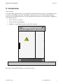
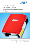
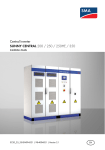
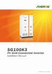
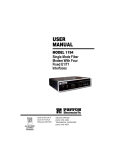
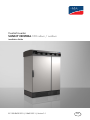
Central inverter
SUNNY CENTRAL 100 indoor / outdoor
Installation Guide
SC-100-IEN093231 | 98-4018331 | Version 3.1
EN
SMA Solar Technology AG
Table of Contents
Table of Contents
1
1.1
1.2
1.3
Notes on this Manual. . . . . . . . . . . . . . . . . . . . . . . . . . . . . .
Validity . . . . . . . . . . . . . . . . . . . . . . . . . . . . . . . . . . . . . . . . . . . .
Target Group . . . . . . . . . . . . . . . . . . . . . . . . . . . . . . . . . . . . . . .
Explanation of the Symbols Used . . . . . . . . . . . . . . . . . . . . . . . .
2
Introduction. . . . . . . . . . . . . . . . . . . . . . . . . . . . . . . . . . . . . . 7
3
3.1
3.2
3.3
3.4
3.5
3.6
3.7
3.8
3.9
3.10
3.11
3.12
3.13
Safety Instructions . . . . . . . . . . . . . . . . . . . . . . . . . . . . . . . . 8
Appropriate Usage . . . . . . . . . . . . . . . . . . . . . . . . . . . . . . . . . . . 8
Personnel . . . . . . . . . . . . . . . . . . . . . . . . . . . . . . . . . . . . . . . . . . 8
About this Manual . . . . . . . . . . . . . . . . . . . . . . . . . . . . . . . . . . . 8
Checking and Storage . . . . . . . . . . . . . . . . . . . . . . . . . . . . . . . . 9
Transport. . . . . . . . . . . . . . . . . . . . . . . . . . . . . . . . . . . . . . . . . . . 9
Installation. . . . . . . . . . . . . . . . . . . . . . . . . . . . . . . . . . . . . . . . . . 9
Special Hazards of Photovoltaic Systems. . . . . . . . . . . . . . . . . 10
Electrical Connection . . . . . . . . . . . . . . . . . . . . . . . . . . . . . . . . 10
Operation . . . . . . . . . . . . . . . . . . . . . . . . . . . . . . . . . . . . . . . . 11
Commissioning, Maintenance and Repair . . . . . . . . . . . . . . . . 12
Power Supplies . . . . . . . . . . . . . . . . . . . . . . . . . . . . . . . . . . . . . 12
Disconnect . . . . . . . . . . . . . . . . . . . . . . . . . . . . . . . . . . . . . . . . 14
General Information . . . . . . . . . . . . . . . . . . . . . . . . . . . . . . . . . 15
4
4.1
4.2
Transport. . . . . . . . . . . . . . . . . . . . . . . . . . . . . . . . . . . . . . . 16
Overview of Weights and Dimensions . . . . . . . . . . . . . . . . . . . 16
Transport Possibilities . . . . . . . . . . . . . . . . . . . . . . . . . . . . . . . . 16
5
5.1
Installation Requirements . . . . . . . . . . . . . . . . . . . . . . . . . 17
Installation Site Requirements . . . . . . . . . . . . . . . . . . . . . . . . . . 17
5.1.1
Foundation . . . . . . . . . . . . . . . . . . . . . . . . . . . . . . . . . . . . . . . . . . . . . . . . . . 17
5.1.2
Minimum Workspace Requirements . . . . . . . . . . . . . . . . . . . . . . . . . . . . . . . 20
Installation Guide
SC-100-IEN093231
5
5
5
6
3
Table of Contents
SMA Solar Technology AG
5.1.3
Inverter Protection Rating / EMC / Sound Levels . . . . . . . . . . . . . . . . . . . . . 20
5.1.4
Ventilation . . . . . . . . . . . . . . . . . . . . . . . . . . . . . . . . . . . . . . . . . . . . . . . . . . . 21
6
6.1
On-Site Inverter Installation . . . . . . . . . . . . . . . . . . . . . . . 24
Mounting on the Foundation. . . . . . . . . . . . . . . . . . . . . . . . . . . 24
7
7.1
Electrical Connection . . . . . . . . . . . . . . . . . . . . . . . . . . . . . 26
External Connections . . . . . . . . . . . . . . . . . . . . . . . . . . . . . . . . 26
7.1.1
AC Grid Power Connections. . . . . . . . . . . . . . . . . . . . . . . . . . . . . . . . . . . . . 26
7.1.2
7.1.3
AC Control Voltage Connection (Optional) . . . . . . . . . . . . . . . . . . . . . . . . . 29
Handling the Connection Terminals . . . . . . . . . . . . . . . . . . . . . . . . . . . . . . . 31
7.1.4
Sensors and Digital Outputs . . . . . . . . . . . . . . . . . . . . . . . . . . . . . . . . . . . . . 31
7.1.5
Inverter Communication Connection . . . . . . . . . . . . . . . . . . . . . . . . . . . . . . . 32
7.1.6
Shield Contact Handling Instructions . . . . . . . . . . . . . . . . . . . . . . . . . . . . . . 32
7.1.7
Sunny String Monitor Communication Connection . . . . . . . . . . . . . . . . . . . . 33
7.1.8
Lightning and / or Overvoltage Protection . . . . . . . . . . . . . . . . . . . . . . . . . . 33
7.1.9
PV Generator Power Connection (DC Connection) . . . . . . . . . . . . . . . . . . . 35
8
8.1
8.2
8.3
Commissioning . . . . . . . . . . . . . . . . . . . . . . . . . . . . . . . . . . 38
Prerequisites . . . . . . . . . . . . . . . . . . . . . . . . . . . . . . . . . . . . . . . 38
Cabling Checks . . . . . . . . . . . . . . . . . . . . . . . . . . . . . . . . . . . . 38
Switch On . . . . . . . . . . . . . . . . . . . . . . . . . . . . . . . . . . . . . . . . . 39
9
Appendix A. . . . . . . . . . . . . . . . . . . . . . . . . . . . . . . . . . . . . 40
10
10.1
10.2
Appendix B . . . . . . . . . . . . . . . . . . . . . . . . . . . . . . . . . . . . . 42
Technical Data SC 100 outdoor. . . . . . . . . . . . . . . . . . . . . . . . 42
Technical Data SC 100 indoor . . . . . . . . . . . . . . . . . . . . . . . . 45
11
Appendix C. . . . . . . . . . . . . . . . . . . . . . . . . . . . . . . . . . . . . 48
12
Appendix D. . . . . . . . . . . . . . . . . . . . . . . . . . . . . . . . . . . . . 50
13
Contact . . . . . . . . . . . . . . . . . . . . . . . . . . . . . . . . . . . . . . . . 51
4
SC-100-IEN093231
Installation Guide
SMA Solar Technology AG
Notes on this Manual
1 Notes on this Manual
1.1 Validity
This installation guide covers the correct installation and commissioning of type SC 100 indoor /
outdoor SMA inverters.
1.2 Target Group
Only trained electricians approved by the responsible energy supply company may install and
commission the inverters. The instructions assume that you, the installer, are familiar with electrical
installations and know the corresponding rules and regulations.
Installation Guide
SC-100-IEN093231
5
Notes on this Manual
SMA Solar Technology AG
1.3 Explanation of the Symbols Used
The following types of safety warnings as well as general information appear in this document:
DANGER!
DANGER indicates a hazardous situation which, if not avoided, will directly result in death
or serious injury.
WARNING!
WARNING indicates a hazardous situation which, if not avoided, could result in death or
serious injury.
CAUTION!
CAUTION indicates a hazardous situation which, if not avoided, could result in minor or
moderate injury.
NOTICE!
NOTICE indicates a situation that can result in property damage if not avoided.
Information
INFORMATION provides tips that are valuable for the optimal installation and operation
of your product.
6
SC-100-IEN093231
Installation Guide
SMA Solar Technology AG
Introduction
2 Introduction
Dear customer,
You have made a good choice in purchasing the Sunny Central solar inverter. To guarantee correct
connection and reliable operation of the device, please take note of the safety and installation
instructions in the following sections. The following extra documents are also available in addition to
the installation guide:
• Sunny Central user manual
• Sunny Central wiring diagrams
• Installation requirements (contains views of the inverter)
Sunny Central 100
SMA
F
i
g
u
r
e
2.1: Sunny Central SC100 Indoor / Outdoor front view
Installation Guide
SC-100-IEN093231
7
Safety Instructions
SMA Solar Technology AG
3 Safety Instructions
The Sunny Central SC100 is built using the latest technology, according to recognized safety
standards. Despite this, hazard to users, third parties or equipment can arise during operation or when
working on the device. These hazards can be reduced to a minimum when the device is used
appropriately as directed.
Faults that affect or limit the safety of the device must be immediately rectified. Unauthorized
modifications and the use of spare parts not recommended by SMA Solar Technology AG may cause
fire, material damage and electrical shock. Unauthorized personnel must not have access to the
equipment.
Warning signs must always be clearly readable and immediately replaced if damaged.
3.1 Appropriate Usage
Appropriate use of the Sunny Central means following all instructions in the installation guide relating
to transport, installation, electrical connection, and commissioning of the equipment.
Any deviation from the installation guide instructions is regarded as inappropriate use of the
equipment. SMA Solar Technology AG accepts no responsibility or liability for any and all damage
resulting from inappropriate use of the equipment.
Appropriate use of the equipment also entails:
• Observation of the safety instructions listed here and in the following sections
• Observation of the instructions in the Sunny Central user manual
• Observation of additional documentation for variants and options, such as grounded operation
(GFDI) and the extended voltage range (EVR)
• Conformance to the device-dependent technical data
3.2 Personnel
Only qualified technical personnel may perform any and all work on the Sunny Central. "Qualified"
means that the personnel must possess training relevant to the activity performed.
For commissioning and operation of the Sunny Central inverter, the personnel must be familiar with
the content of the Sunny Central documentation. In particular, the safety instructions must be followed.
3.3 About this Manual
This manual was written with the greatest possible care. However, discrepancies cannot be excluded.
SMA Solar Technology AG accepts no responsibility or liability for injury to persons, or material
damage caused by mistakes in this manual.
8
SC-100-IEN093231
Installation Guide
SMA Solar Technology AG
Safety Instructions
3.4 Checking and Storage
Upon receipt of the equipment, check the packaging and the device for any possible damage and
compare the contents of the delivery with the delivery documentation. In the case of damage to the
device and/or unclear delivery contents, please contact SMA Solar Technology AG immediately
(contact address is in the appendix).
The equipment may only be stored when closed, thus ensuring its interior is protected from
dust and moisture.
During longer storage periods, the equipment must be kept in a dry place to prevent
moisture from entering the inverter.
3.5 Transport
Only the transport methods described in the installation guide are permissible. Please note the heavy
weight of the equipment and the non-central center of gravity. The center of gravity is marked on the
packaging.
WARNING!
Danger of tipping during transport.
Follow the "Sunny Central Transport Instructions" in Appendix A and pay attention to the
center of gravity markings on the packaging.
3.6 Installation
The information contained in the installation guide must be observed when installing the inverter. The
SC 100 Indoor is designed for indoor installation, with a protection rating of IP21. The SC 100
Outdoor is designed for outdoor installation, with a protection rating of IP44/54. The device must be
installed in a manner such that the proper electrical connections, adequate ventilation, and adequate
fire protection are possible.
The Sunny Central SC100 Outdoor product line has been type-tested and approved for outdoor
installation in accordance with the industry-standard EMC limits (EMC = Electro Magnetic
Compatibility).
Please observe the additional information on installing the SC 100 Outdoor located in
Appendix C.
Installation Guide
SC-100-IEN093231
9
Safety Instructions
SMA Solar Technology AG
3.7 Special Hazards of Photovoltaic Systems
DANGER!
An active power source is connected!
Photovoltaic systems have special characteristics representing special hazards:
• An active power source is connected. This means that, depending on the operating mode, there
may be voltage present, either from the photovoltaic generator and/or the Sunny Central. This
is especially important to note when disconnecting particular parts of the system
• Very high DC voltages are present (no zero-crossing) which, in case of a fault or inappropriate
use of fuses or plugs, may lead to arcing.
• The short-circuit current of the photovoltaic generator is only slightly more than the maximum
operating current and is also dependent on the level of solar irradiation. This means that, if a
short circuit occurs in the system, the existing circuit breakers are not guaranteed to switch off.
• A highly branched generator array may be difficult to disconnect if a fault develops (e.g. short
circuit). We recommend the extra use of external DC circuit breakers for disconnecting the
inverter and/or the DC main cables / Sunny String monitors (DC circuit breakers optionally
available). One circuit breaker should be allocated to each input, and these should be located
near to the Sunny Central, as described in the standard VDE 0100 part 7-712 and the
VDI 6012 regulations.
3.8 Electrical Connection
The electrical connection must be performed according to the installation guide, the device connection
plan and the technical data of the device.
AC Grid Connection
The customer must determine the required grid connection type for the AC grid connection
(TN-C, TN-S, TT grid) and coordinate it with SMA.
Ensure the grid connection cable for grid feeding is fused at the nominal current indicated on the name
plate. If the specified nominal current differs from the nominal current of the fuse plug, the fuse plug
having the next highest nominal current may be used. A power switch is used for the optional loaddisconnecting switch.
An external input control voltage (optional) must be fused with a circuit breaker conforming to the
specifications in Appendix B (SC100 Indoor / Outdoor technical data).
NOTICE!
SMA must be informed of the required AC grid connection type!
10
SC-100-IEN093231
Installation Guide
SMA Solar Technology AG
Safety Instructions
Lightning / Overvoltage Protection
The device has internal overvoltage protection on the DC side and, depending on the option chosen,
also has lightning and/or overvoltage protection on the AC side. The desired level of protection can
only be achieved when the grid connection point has a Lightning Protection Zones Concept in
compliance with DIN VDE 0185-3 (DIN EN 62305 / VDE 085, part 305-3). In keeping with the
Lightning Protection Zones Concept, there are lightning conductors and combined overvoltage
protectors which are not included in the scope of delivery for the equipment and which must be
installed at the entrance (transfer point from lightning protection zone LPZ 0 to LPZ 1).
We recommend using lightning protection for the PV generator.
A direct strike can irreparably damage the overvoltage protectors or other system
components and cause additional consequential damages.
We recommend expanding the lightning and overvoltage protection for external input
control voltage. Please see section 7.1.9 Lightning and Overvoltage Protection.
Emergency Shut-off
The inverter is not equipped with an external emergency shut-off switch.
An external emergency shut-off switch or the external emergency shut-off function for more than one
device can be ordered as an option (emergency shut-off circuit).
WARNING!
The emergency shut-off circuit may only be supplied with power from a single Sunny
Central.
3.9 Operation
Apart from the Sunny Central Control, there are no control elements on the device. The cabinet doors
must only be opened for commissioning, maintenance and troubleshooting, as well as for data query
and parameter setting. Before opening, the device must be switched off using the key switch. Please
also note the following safety instructions for working on the device.
DANGER!
Before opening the door, the Sunny Central must be switched off using the key switch!
The Sunny Central must not be operated with the door open!
Installation Guide
SC-100-IEN093231
11
Safety Instructions
SMA Solar Technology AG
3.10 Commissioning, Maintenance and Repair
All work on the Sunny Central may only be performed when the device is safely disconnected from
the PV voltage, the grid voltage, and the internal power supply, when these power sources are
secured against being switched on again, and when it has been checked that the device is voltagefree. Only qualified technical personnel, who are familiar with the operation of the system, may
undertake any such work.
3.11 Power Supplies
Switching on of the external power supplies
• Grid voltage for the grid feed-in
• Grid voltage for control voltage (internal power supply). There is the option of feeding it
externally.
• DC voltage from the photovoltaic generator must occur in the sequence described and may only
be performed when the following conditions are satisfied:
• All connections have been made according to the installation guide and the wiring diagram.
• The protective ground connection for grid feed-in and for internal power supply has been made.
• The device is switched off. This means that the Start/Stop switch is in the “Stop” position and
the main switches are off.
• The Plexiglas covers are mounted, to ensure protection against accidental touching.
• The nominal voltage, frequency and the right-hand rotary field are maintained (see device
technical data).
• The polarity of the DC voltage at the inputs / fuse inputs (device dependent) has been checked.
• The photovoltaic generator has been checked with an insulation test to ensure that there is no
ground fault.
12
SC-100-IEN093231
Installation Guide
SMA Solar Technology AG
Safety Instructions
Figure 3.1: Sunny Central SC100 interior view
DANGER!
The protective ground connection must be made before the external voltage is switched on!
Installation Guide
SC-100-IEN093231
13
Safety Instructions
SMA Solar Technology AG
NOTICE!
The nominal voltage, frequency and right-hand rotary field are maintained at the AC grid
connection.
DANGER!
The cabinet must remain closed when connecting the supplies!
3.12 Disconnect
External insulation of the device must always occur under load-free conditions. The device must be
switched off in order to do this. This means that the key switch must be in the “Stop” position.
Work on the Sunny Central may be performed only after switching off the power to the
unit. The VDE regulations must be followed.
• Disconnect
• Protect against reenergizing
• Test each unit to ensure that all voltages have been removed
• Ground and short the unit if necessary (not on the DC side)
If necessary, cover or protect against accidental contact with any voltage carrying
components
The following power supplies must be isolated:
• Grid voltage for the grid feed-in
• Grid voltage for internal power supply (optional)
• DC voltage from the photovoltaic generator
Simply switching off the main AC and DC switches is not sufficient to ensure proper insulation of the
device. The main switches only separate the power circuit from the grid and the photovoltaic
generator.
DANGER!
Dangerous accidental-contact voltages can be present in the device even when the main
AC and DC switches are switched off!
DANGER!
In case of a failure, the DC contactor(s) may carry a life-threatening DC voltage!
14
SC-100-IEN093231
Installation Guide
SMA Solar Technology AG
Safety Instructions
We recommend the extra use of external DC circuit breakers (optionally available) for
disconnecting the Sunny Centrals and/or one or more DC main cables / Sunny String
monitors. Even in the case of faults or fire, this allows system components to be safely
isolated.
The device contains capacitors on the AC and DC sides that must discharge once the device has been
switched off. After switching off, there are dangerous accidental-contact voltages present within the
device for several minutes. If there is a fault in the device, these voltages may also remain present for
a longer period of time. For these reasons, wait a minimum of 5 minutes after switching off before
opening the device.
WARNING!
The discharge time of the capacitors is longer than 5 minutes.
3.13 General Information
Working on the Fans
The device is equipped with several fans for cooling. Work on the fans may only be performed after
all insulation measures have been taken, in exactly the same manner as prescribed for commissioning,
maintenance and repair work.
WARNING!
Warning: rotating fans in the inverter!
Hearing Protection
The device fans and the power unit create significant levels of operating noise. In addition to this, a
fault in the device can lead to very high sound levels. For these reasons we recommend the use of
hearing protection in its vicinity.
We recommend the use of ear protection when in the vicinity of the device for extended
periods.
Burns
Immediately after isolating the device, depending on the operating conditions, certain components
can be very hot (e.g. fuses, transformer core, sine wave filter, heatsinks etc.).
Safety gloves should always be worn when working near components that can be expected to be
very hot.
We recommend that safety gloves be worn during all work on the device.
Installation Guide
SC-100-IEN093231
15
Transport
SMA Solar Technology AG
4 Transport
Only the transport methods described in the installation guide are permissible, please follow the
transport requirements in Appendix A.
When delivered, the inverter stands on a pallet. Under standard delivery conditions, a forklift must be
available. When unloading, the heavy-load markings must be observed, without exception.
4.1 Overview of Weights and Dimensions
Please note the heavy weight of the inverter. To assist with transporting, the data sheet on the
dimensions and weight is contained in Appendix B.
The center of gravity of the cabinet unit is marked on the outside of the packaging.
WARNING!
Heavy weight of the cabinet unit! Danger of tipping during transport!
The cabinet must always be transported upright.
Be sure to follow the “Instructions for Transporting Sunny Central Inverters” in
Appendix A!
4.2 Transport Possibilities
Transporting Using a Pallet Truck / Crane
The plinth panels must be unscrewed to transport the cabinet without a palette. This allows the fork of
a pallet truck / forklift or crane to be inserted under the cabinet.
Please note the Sunny Central transport requirements in Appendix A.
16
SC-100-IEN093231
Installation Guide
SMA Solar Technology AG
Installation Requirements
5 Installation Requirements
For safe operation of the inverter, the installation site must satisfy the following conditions:
• Foundation (load carrying capacity)
• Inverter protection rating / EMC / sound levels
• Minimum workspace requirements (escape routes)
• Ventilation / permissible ambient temperature / air quality / humidity
5.1 Installation Site Requirements
5.1.1 Foundation
The foundation must guarantee solid and safe positioning of the inverter. It must provide the loadcarrying capacity necessary to cope with the weight of the inverter. A foundation slab is required for
ground-mounted installations. Pouring and dimensioning the foundation slab must be performed by
the customer, see Appendix D.
ventilation system (option customer)
A1
D
E
F
Sunny Central 100
G
B
F
H
SMA
SMA
C
C
Cable section (option customer)
Cable section (option customer)
Figure 5.1: Installation of the SC100 Indoor in a building
Installation Guide
SC-100-IEN093231
17
Installation Requirements
SMA Solar Technology AG
Sunny Central 100
SMA
Concrete foundation slab
Concrete foundation slab
Figure 5.2: Installation of the SC100 Outdoor with concrete foundation slab
Pouring and structural inspection of the foundation slab should be performed on-site.
The inverter cabinet must be installed on a level surface. Any existing unevenness, depressions or
slope must be corrected prior to installation.
When pouring the foundation, keep in mind that the cables and conduits should enter the inverter from
underneath. This means that suitable conduits or cable feed-throughs should be installed prior to
pouring.
NOTICE!
The cable must be routed into the inverter from below.
The cable routing through the removable base plates in the Sunny Central is displayed in
figure 5.3.
The control voltage and communication cables must be installed separately.
18
SC-100-IEN093231
Installation Guide
Installation Requirements
cable entry
cable entry
Sine wave filter and fan
Transformer
Concrete base
SMA Solar Technology AG
Figure 5.3: Different cable feeds from the front and from the rear; the cable must be routed into the
foundation plate from below
Dimensioning the concrete foundation and cable feed pipes through the concrete
foundation must be performed by the customer.
Installation Guide
SC-100-IEN093231
19
Installation Requirements
SMA Solar Technology AG
5.1.2 Minimum Workspace Requirements
When installing the inverter, appropriate clearances to stationary objects and neighboring inverters
must be observed. Minimum passage widths, escape routes, and minimum clearances for optimal
ventilation are to be guaranteed. The corresponding specifications are contained in Appendix C.
The technical diagrams with the dimensions are contained in the Sunny Central installation
requirements.
Refer to the national applicable standards for installing and connecting the Sunny Central inverter. In
Germany, the requirements for passage widths and escape routes in electrical operating sites and the
installation of high voltage systems of up to 1000 V are regulated by DIN VDE 0100 part 729,
part 731.
WARNING!
With fully opened cabinet doors, a minimum passage width of 500 mm (escape route)
must be maintained.
To maintain the minimum passageway requirements, the cabinet doors in an inverter
system with two rows of opposing cabinets may only be opened on one side at a time.
The minimum clearances and passage widths to be maintained along with the corresponding
dimensions are contained in Appendix C.
5.1.3 Inverter Protection Rating / EMC / Sound Levels
The outdoor version of the Sunny Central SC 100 is suitable for outdoor installation according to the
IP44 protection rating. The control area is enclosed from the power area and has IP54 protection
rating. The indoor version of the Sunny Central SC 100 is suitable for installation in a station located
in a dry, dust-reduced environment according to protection rating IP21. With regard to the EMC
emissions and the noise level, the inverter is conceived for setup in an industrial environment or for
outdoor installation.
20
SC-100-IEN093231
Installation Guide
SMA Solar Technology AG
Installation Requirements
5.1.4 Ventilation
Ambient Temperature / Air Quality / Humidity
To cool the inverter, the ventilation system must be free of any obstructions in order to ensure the
required inlet ventilation and heat dissipation.
The specified minimum clearances in Appendix C must be maintained for this purpose.
For safe operation, and maximum feed-in performance, the permissible ambient temperature is
between -20 and +50 °C. The rated values can be ensured at ambient temperatures of up to +40 °C.
The air required for the SC 100 Outdoor is drawn through the ventilation system on the roof of the
inverter. Therefore, the corresponding device openings must be kept free and clean according to the
maintenance intervals specified in the user manual. The air required for the SC 100 Indoor can either
be drawn through the ventilation system on the roof of the inverter or fed directly to the inverter
through an air duct that is provided by the customer.
The exhaust air (waste heat) is blown out through the front plinth panels. The exhaust air of the SC
100 Indoor is blown out through an air duct in the roof of the inverter.
If the SC 100 Outdoor is exposed to direct sunlight, the internal temperature in the inverter can
increase and thus lead to a reduction in the output power. In this case, we recommend using a sun
shading system or installing the device in a shaded area or under a module table. In case of existing
buildings, the shaded area at the north side of the building should be used.
Figure 5.4: View of the ventilation concept of the SC 100 Outdoor
Installation Guide
SC-100-IEN093231
21
Installation Requirements
SMA Solar Technology AG
SMA
SMA
SMA
SMA
Figure 5.4: View of the ventilation concepts of the SC 100 Indoor
22
SC-100-IEN093231
Installation Guide
SMA Solar Technology AG
Installation Requirements
NOTICE!
Install with unobstructed ventilation system!
NOTICE!
Regular cleaning of the outer air inlets and the inner cover grid!
NOTICE!
The device must not be installed in direct sunlight!
NOTICE!
The device must not be installed in environments with salty air!
The inlet air for the SC 100 Outdoor must satisfy the requirements of classification 4S3, whereas the
inlet air for the SC 100 Outdoor must satisfy the requirements of classification 4S3 (see the following
table). The operation of the inverter is suited to a relative humidity of 15 to 95 %.
Air Quality Classification
Environmental requirements for fixed site use
Class
3S1
3S2
3S3
3S4
a) Sand in the air
mg/m³ -
30
300
3000
b) Dust (suspended matter)
mg/m³ 0,01
0.2
0.4
4.0
c) Dust (fallout)
mg/m³ 0.4
1.5
15
40
x
x
x
x
x
x
x
x
Sites where dust fallout is kept to a minimum through
appropriate measures.
Sites where no special measures have been taken to reduce the
sand or dust levels and which are far from sand and dust
sources
Sites near sand and dust sources
x
Sites in production halls where sand or dust is present, or sites
in geographical locations in which the air can contain high
quantities of sand and dust.
x
Please observe the requiremets for air quality, relative humidity, fresh air volume and
permissible ambient temperature.
Installation Guide
SC-100-IEN093231
23
On-Site Inverter Installation
SMA Solar Technology AG
6 On-Site Inverter Installation
6.1 Mounting on the Foundation
Removing the Transport Locks
The inverter must be fixed to the foundation or foundation slab. Therefore, the respective attachment
points (wall anchors, threaded bolts) must be in place before installation. A rig close to the base of
the device facilitates its attachment to the foundation. The corresponding figure is found in
Appendix D.
Attaching the inverter to the foundation or the foundation plate.
After attaching the device to the foundation, remove the transformer transport lock. This consists of an
iron right-angle that is fastened to the side of the cabinet.
Angle bracket
Figure 6.1: View of transformer transport lock with sidewall removed
24
SC-100-IEN093231
Installation Guide
SMA Solar Technology AG
On-Site Inverter Installation
After the cabinet has been installed, the provided grid must be mounted below the transformer using
the provided wing bolts.
The grid must be mounted before the plinth panels are mounted.
Detachable grid
Figure 6.2: Side view with transformer
Installation Guide
SC-100-IEN093231
25
Electrical Connection
SMA Solar Technology AG
7 Electrical Connection
After the inverter has been installed and mechanically attached, the electrical connection can be
established.
The cables are fed from below through the socket and the base of the cabinet. To do this, the base
plates in the front of the cabinet are to be opened and the cable pulled into the inside of the cabinet.
The corresponding cable screw connections must be installed in the removable base plates in order
to seal the cable routing and to provide strain relief for the cable. A range of various screw fitting sizes
is provided for this purpose.
The device-specific wiring diagram provided must be used for establishing the connections!
7.1 External Connections
7.1.1 AC Grid Power Connections
The AC grid connection is made at the TN-C, TN-S, TT grid connection type, which must be provided
by the customer, using a 3-phase system equipped for 400 V.
The connection terminals are located in the front chamber, on the right-hand lower area of the
sidewall.
SMA must be notified of the required AC grid connection type during the project planning
phase!
NOTICE!
Cable screw connections must be installed in the base plates to provide strain relief for the
AC cables!
The AC cables are connected using cable lugs on M12 bolt clamps.
CAUTION!
The grid connection must be installed in a way such that a right-hand rotary field lies at the
input of the cabinet. A left-hand rotary field will cause the frequency values to be displayed
as negative values. The correct phase sequence must also be followed.
26
SC-100-IEN093231
Installation Guide
SMA Solar Technology AG
Electrical Connection
NOTICE!
DC connection
Base plate and cable feed
AC connection
Ensure the grid connection cable is fused at the nominal current indicated on the name
plate. If the specified nominal current differs from the nominal current of the fuse plug, the
fuse plug having the next highest nominal current may be used.
Figure 7.1: View of the base plates for cable routing and the SC100 electrical connections
Installation Guide
SC-100-IEN093231
27
Electrical Connection
SMA Solar Technology AG
Figure 7.2: Differnet kind of AC grid connection terminals
28
SC-100-IEN093231
Installation Guide
SMA Solar Technology AG
Electrical Connection
7.1.2 AC Control Voltage Connection (Optional)
The 1 x 230 V power required for driving the internal circuits of the Sunny Central SC100 is taken
internally from the grid-feed-in line of the inverter. This reduces the feed-in energy yields by the amount
of power required by the inverter itself (fans, heating etc.).
The energy required for driving the Sunny Central SC100 Outdoor can be provided optionally from
an external source. The connection to the control voltage supply is made 1-phase to a TN-S grid
connection. The standard bridges in the connection terminal strip, as shown in the wiring diagram,
must therefore be removed and the separate supply cable must be connected.
In doing so, please note that the external supply cable should also be protected against lightning and
overvoltage. This can be ordered optionally.
The connection of an external control voltage supply is established on 3 x 2.5 mm² springtype terminals.
NOTICE!
When an external control voltage supply cable is connected, the lightning and overvoltage
protection at this voltage input is rendered useless! See section 7.1.8 Lightning and
Overvoltage Protection.
Installation Guide
SC-100-IEN093231
29
Connection terminals for external control
voltage with plugged bridges
NET connection
PT 100 Temperature sensor, to be equipped
optionally with overvoltage protectors
Sensor inputs, to be equipped optionally with
overvoltage protectors
Electrical Connection
30
SC-100-IEN093231
SMA Solar Technology AG
Figure 7.3: Connection terminal for external control voltage (optional), the sensor inputs and the
communication
Installation Guide
SMA Solar Technology AG
Electrical Connection
7.1.3 Handling the Connection Terminals
The following figure shows the correct method for handling the terminals used for connecting external
cables to the control terminal strip. The connection terminals are designed as maintenance-free springloaded terminals that can be operated using a suitable screwdriver.
Figure 7.4: Handling the connection terminals (source: Wago)
WARNING!
The connections should only be made under voltage-free conditions!
7.1.4 Sensors and Digital Outputs
Two analog sensors and one PT100 temperature sensor can be connected to the Sunny Central. The
connection is made in the device's connection area. Please refer to the provided wiring diagram for
the signal assignment of the connection terminals.
Further information about the connection and parameterization of analog sensors is contained in the
Sunny Central user manual. We recommend equipping the first sensor inputs with an overvoltage
protector, available as an option. The sensors are connected directly to the overvoltage protector, see
figure 7.3.
Please note the connection possibility of the analog sensors in four-wire or two-wire system
and the required transducers, if necessary.
Please take note of the comprehensive description in the Sunny Central user manual
provided.
Installation Guide
SC-100-IEN093231
31
Electrical Connection
SMA Solar Technology AG
7.1.5 Inverter Communication Connection
The device can be equipped with various interface cards (Net Piggy Back) for the communication
between the inverter and a PC or modem.
The data can be transferred using the following Net Piggy Back versions:
• Analog
• ISDN
• Ethernet
• GSM (combining Net Piggy Back Ethernet + GSM router)
The data cable is connected via the NET interface (RJ45 socket), see figure 7.3.
The length of the data lines must be taken into account when planning or establishing the
communication. An optimum and project-related plan for the data transfer should be coordinated with
SMA.
7.1.6 Shield Contact Handling Instructions
The external signal and bus cables must be shielded. The shield must contact the shield rail, provided
for this purpose, along a large surface area. Contact is achieved using the shield clamps provided in
the accessories kit. The correct handling of the shield clamps is shown in the following figure. The
shield clamps must only be hand-tightened, never use a screwdriver. Screwing the clamps with a
screwdriver can damage the cable insulation.
Do not screw in the shield clamps with a screwdriver, hand-tighten only.
Figure 7.5: Handling the shield clamps (source: Wago)
32
SC-100-IEN093231
Installation Guide
SMA Solar Technology AG
Electrical Connection
7.1.7 Sunny String Monitor Communication Connection
The communication between the Sunny Central Control unit in the inverter and the Sunny String
Monitors equipped with integrated string current monitoring is conducted via RS485 data line. The
data cable is connected directly to the Hub in the Sunny Central and afterwards to the Sunny Central
Control, see figure 7.6
NOTICE!
First connect the Sunny String-Monitors to the data cable and after that the Sunny Central.
.
SMA
Sunny Central 100
l
ny
SunCentra
SMA
U1-A6
Power
+55V
SSM
SCC
String Monitor
RS485
IN
Power Supply Unit / Hub
FUSE
RS485
OUT
SSM
www.SMA.de
1
DataData+
GND
GND
+55V
+55V
2
AC
2
L+
1
1
2
2
3
3
4
4
5
1
L
L
N
N
NC
PE
PE
L-
5
6
6
7
7
8
8
1
1
2
2
3
3
4
4
5
5
6
6
7
7
8
8
1
2
3
4
5
6
7
8
9
10
11
12
13
14
15
LZ2-X2
Z1-X1
Z9-X9
L+
123456
16
L+
1
2
3
4
5
6
7
8
9
10
11
12
13
14
15
16
LL+
L-
Figure 7.6: Connection of the data line to the Sunny Central
It is essential that you follow the instructions of the comprehensive description in the Sunny
String Monitor user manual provided and in the wiring help „Connection of the
communication in the SSM“.
7.1.8 Lightning and / or Overvoltage Protection
The Sunny Central SC100 Outdoor is equipped with internal lightning and overvoltage protection. In
this case, the AC/DC connection and the RS485 interface for connecting the Sunny String Monitors
is protected. Optionally, the analog signal input of an external temperature sensor (see wiring
diagram) can also be protected against lightning and overvoltage.
If the control voltage is supplied by an external cable, the existing overvoltage protection must be
expanded. We therefore also recommend equipping the control voltage input with combined
overvoltage and lightning protection. This can be retrofitted as an option.
Installation Guide
SC-100-IEN093231
33
Electrical Connection
SMA Solar Technology AG
Figure 7.8: Lightning and overvoltage protection system for protecting the AC feed-in system and the
control voltage supply
Figure 7.9: Overvoltage protection system for protecting the DC inputs
34
SC-100-IEN093231
Installation Guide
SMA Solar Technology AG
Electrical Connection
We also recommend an optimum protection level at the grid connection point by installing
combined overvoltage and lightning protection there as well.
The analog input of the external temperature sensor and both additional analog signal inputs are not
equipped with lightning and overvoltage protection as a standard feature. This can be retrofitted as
an option.
Before measuring the insulation, the overvoltage protectors must be removed or
disconnected or the existing fuses must be removed!
We recommend using lightning and overvoltage protection for the external temperature
sensor and for both of the available analog inputs. This can be ordered as an option.
NOTICE!
When an external control voltage supply cable is connected, the lightning and overvoltage
protection at this voltage input is rendered useless! We therefore recommend the option of
retrofitting the device with combined lightning and overvoltage protection!
The grid structure, in particular the special feature of the TT grid must be observed.
7.1.9 PV Generator Power Connection (DC Connection)
A busbar that allows string distribution boxes to be connected is located in the left lower area of the
inverter sidewall. Cables rated for a minimum of 900 V are required for connecting the DC cables to
the fuse inputs of the inverter. The voltage resistance must be at least 1000 V for inverters that are
equipped with an optional EVR. The SC100 is equipped with 3 DC inputs (see data sheet
Appendix B).
The cables are fed through the socket and the base of the cabinet. To do this, the base plates in the
front of the cabinet are opened and the cable pulled into the inside of the cabinet. Suitable cable
screw connections must be installed in the removable base plates to provide strain relief for the cable.
A variety of threaded joint sizes is provided for this purpose.
The DC cables are connected directly to the busbar using M12 cable lugs. See the
electrical connection section in the table located in Appendix C.
NOTICE!
The DC cables to be connected must be rated for a minimum of 900 V. They must have a
voltage resistance of at least 1000 V for an optional EVR.
Installation Guide
SC-100-IEN093231
35
Electrical Connection
SMA Solar Technology AG
NOTICE!
The DC voltage of the PV generator must never exceed the maximum permissible inverter
input voltage.
Otherwise the inverter is in acute danger when connected! UPV < 900 / 1000 V!
NOTICE!
All cable feeds and base plates must be locked tightly so that no small animals can enter
the device!
NOTICE!
Since the Sunny Central is not equipped with a fuse, the DC cables to be connected must
be designed for at least 2/3 of the maximum generator current rating.
36
SC-100-IEN093231
Installation Guide
SMA Solar Technology AG
Electrical Connection
Figure 7.5: View of the DC connection area
Installation Guide
SC-100-IEN093231
37
Commissioning
SMA Solar Technology AG
8 Commissioning
NOTICE!
Before starting the device for the first time (commissioning), all work performed on the
device should be thoroughly checked. In particular, the voltages on the DC and AC sides
should be checked for conformance with the limits allowed on the inverter.
8.1 Prerequisites
To allow the inverter to be correctly commissioned, the following conditions must be satisfied in
advance before the device is put into operation.
The PV generator must be constructed and tested in compliance with to VDE 0100 part 610 BGV A2
"Electrical Systems and Appliances". The grounding resistance is decisive for the safety of the
complete system and must therefore be determined before the system is started for the first time.
When delivered, all circuit beakers and motor overload switches in the Sunny Central are switched
off.
8.2 Cabling Checks
When performing the cabling checks, the connections are first checked for correctness and proper
installation.
AC Grid Connection
The connection made to the feed-in cables is 3-phase. It must be checked that the inverter is connected
to the correct grid connection type (TN-C, TN-S or TT) and that a right-hand rotary field exists on L1,
L2 and L3. The level of the AC voltage should be measured and logged. The Sunny Central feeds into
the grid using 3 x 400 V (+/- 10 %).
AC Control Voltage Connection (Optional)
The connection made to the feed-in cables is 1-phase. Have the bridges in the connection terminal
strip been removed and has a separate supply cable been connected for the external AC control
voltage? Has the external AC control voltage been connected to the correct grid connection type
(TN-S)?
DC Power Connections
The DC power connections are made over the main DC cables to the inverter. The voltage on the
individual DC main cables should be almost identical and must never exceed the maximum DC
voltage of the inverter.
In addition to the voltage levels, the polarity of the individual DC main cables must also be checked.
The wrong polarity in one of the DC main cables can also damage the PV generator. Again, all DC
connections should be checked to ensure that they are mechanically tight.
38
SC-100-IEN093231
Installation Guide
SMA Solar Technology AG
Commissioning
Serial Interfaces
For external communication and string current monitoring, the data cables must be connected.
Settings for the Hygrostat
The device contains an adjustable hygrostat for controlling the cabinet ventilators and the overheating
shut-off system. The hygrostat is pre-adjusted before delivery.
Prior to commissioning, please check whether the settings agree with the information in the
wiring diagram. If deviations are found, please set the values specified in the wiring
diagram.
8.3 Switch On
If all tests and measurements have been performed, and all measured values lie within the acceptable
range, then the device can be switched on for the first time.
All circuit breakers and motor overload switches in the Sunny Central are to be switched on.
Now the inverter is completely connected on the AC and DC sides and can be switched on using the
key switch. Close the cabinet doors and turn the key switch to the right to the “Start” position.
The Sunny Central will now start automatically. First, the grid voltage and frequency parameters are
checked. After approx. 20 seconds, the motorized DC breaker is activated automatically and
connects the PV generator.
Please follow the Sunny Central user manual for the continued operation of the inverter.
Installation Guide
SC-100-IEN093231
39
Appendix A
SMA Solar Technology AG
9 Appendix A
Notes on Transporting
Sunny Central Inverters
(SC 100 outdoor / indoor)
The aim: to avoid damage or accidents during transport by the shipping company and on the
construction site.
The following measures have been introduced to achieve this aim:
• For delivering SC central inverters, all shipping companies have generally agreed not to transfer
the cabinets between transporters.
• After being packed, all cabinets shall be labeled on the front and rear sides with the
international center of gravity symbol (see figure A). The symbols shall be sprayed on using a
stencil.
• In addition, transport instructions shall be affixed to the inverter (see figure A). The transport
markings stipulate that forklift or pallet trucks must always load the switch cabinets by their long
sides (front and rear sides of the SC). It is forbidden to lift them by their short sides.
• Transport by crane is allowed if a suitable crane fork is used that is pushed through the openings
in the base of the switch cabinet (figure A).
• Transporing them using the eyelets on the top of the cabinet is not allowed (SC specific, see
overview table).
• The manufacturers shall ensure that “high quality” pallets are used.
• The cabinets must not be tilted.
40
SC-100-IEN093231
Installation Guide
SMA Solar Technology AG
Appendix A
Figure A: Transport instructions for Sunny Central (SC) inverters
Forbidden
Permitted and must be observed
Center of gravity
marking
SMA
“Tilting”
"Crane fork"
“Suspending
from eyelets”
“Loading from
the side”
Installation Guide
With “forklift/
pallet truck”
SC-100-IEN093231
41
Appendix B
SMA Solar Technology AG
10 Appendix B
10.1 Technical Data SC 100 outdoor
Sunny Central data
Symbol
SC 100 outdoor
Max. PV power (recommended)
PPV
110 kWp a)
DC voltage range, MPPT
UDC
450 - 820 V
Max. permissible DC voltage
UDC, max
900 V / optional
1000 V
Max. permissible DC current
IDC, max
235 A
Voltage ripple, PV voltage
UPP
Input data
Number of DC inputs / terminal not secured
<3%
3 x positive (120 mm²)
M12 screws
3 x negative (120 mm²)
M12 screws
Output data
Nominal AC output power
PAC
100 kW
Operating grid voltage +/- 10 %
UAC
400 V
Nominal AC current
IACnom
145 A
Grid structure
TT, TN-S, TN-C grid
Operating grid frequency
fAC
50 Hz - 60 Hz
Harmonic distortion of grid current
KIAC
< 3 % at nominal power
output
Power factor
cos ϕ
≥
0.99 at nominal power
output
Efficiency per IEC61683
10 % ; 25 % ; 50 % ; 75 % ; 100 %
of PACnom
η10, 25, 50, 75, 100
94,2 / 96,4 / 96,7 /
96,4 / 96,2 %
Euro ETA
ηeuro
96.2 %
,Dimensions and weight
42
SC-100-IEN093231
Installation Guide
SMA Solar Technology AG
Appendix B
Sunny Central data
Symbol
SC 100 outdoor
Width x Height x Depth [mm]
W/H/D
1270 / 1850 / 870
Weight (approx.)
m
925 kg
Operating consumption
Pday
< 1 % of PACnom
Standby operating consumption
Pnight
< approx. 50 W
Power consumption
External auxiliary voltage / grid structure
optionally 230 V,
50/60 Hz TN-S grid
External back-up fuse for auxiliary supply
B 16 A, 1-pole
SCC (Sunny Central Control) interfaces
Communication (optional)
Analog, ISDN, Ethernet,
GSM
Analog inputs
optionally1x PT100,
2x Ain b)
Overvoltage protection for analog inputs
optional
Sunny String Monitor interface
COM1
RS485
PC interface
COM3
RS232
Voltage-free contact (ext. failure)
1
Features
Cabinet color
roof + base RAL 7024
housing 9022
Display
SCC
yes
Ground fault monitoring
yes (optional)
Heating
yes
Emergency stop
no
Power switch AC side
yes
Power switch DC side
motor-driven
Monitored overvoltage protectors AC
optional
Monitored overvoltage protectors DC
yes
Monitored overvoltage protectors for
auxiliary supply
optional
Installation Guide
SC-100-IEN093231
43
Appendix B
SMA Solar Technology AG
Sunny Central data
Symbol
SC 100 outdoor
Standards
EMC
EN 61000-6-2,
EN 61000-6-4
Grid monitoring
per VDEW regulations
CE conformity
yes
Protection rating and ambient conditions
Protection rating per EN 60529
IP44 / IP54
Permissible ambient temperature
T
-20 °C ... +50 °C c)
Relative humidity, not condensing
Uair
15 ... 95 %
Max. altitude (above sea level)
1,000 m
• Classification of
chemically active
substances: 4C1
Air quality (minimum requirements) per
EN 60721-3-3
ambient conditions, fixed location, without
special protection
• Classification of
mechanically active
substances: 4S2
against wind and weather.
Fresh air consumption
2,300 m³/h
Vair
Air duct for outdoor installation
drawn through roof
blown out through base
a)
Specifications apply to irradiation values = 1000
b)
Terminal for an analog sensor provided by the customer in two-wire systems
c)
Compliance with nominal values up to an ambient temperature of +40 °C, with an ambient
temparature of +50 °C maintanance of the nominal values up to two houres
kWh
kWp ⋅Year
Please note:
• the “Sunny Central Transport Instructions”,
• the “Sunny Central Installation Guide”,
• when installing the SC 100 Outdoor, a suitable foundation, sufficient ventilation and
appropriate sun shading systems are necessary
44
SC-100-IEN093231
Installation Guide
SMA Solar Technology AG
Appendix B
10.2 Technical Data SC 100 indoor
Sunny Central data
Symbol
SC 100 indoor
Max. PV power (recommended)
PPV
110 kWp a)
DC voltage range, MPPT
UDC
450 - 820 V
Max. permissible DC voltage
UDC, max
900 V / optional 1000 V
Max. permissible DC current
IDC, max
235 A
Voltage ripple, PV voltage
UPP
Input data
Number of DC inputs / terminal not secured
<3%
3 x positive (120 mm²)
M12 screws
3 x negative (120 mm²)
M12 screws
Output data
Nominal AC output power
PAC
100 kW
Operating grid voltage +/- 10 %
UAC
400 V
Nominal AC current
IACnom
145 A
Grid structure
TT, TN-S, TN-C grid
Operating grid frequency
fAC
50 Hz - 60 Hz
Harmonic distortion of grid current
KIAC
< 3 % at nominal power
output
Power factor
cos ϕ
≥ 0.99 at nominal power
output
Efficiency per IEC61683
10 % ; 25 % ; 50 % ; 75 % ; 100 %
of PACnom
η10, 25, 50, 75, 100
94.2 / 96.4 / 96.7 /
96.4 / 96.2 %
Euro ETA
ηeuro
96.2 %
Width x Height x Depth [mm]
W/H/D
1270 / 1610 / 805
Weight (approx.)
m
925 kg
Dimensions and weight
Installation Guide
SC-100-IEN093231
45
Appendix B
SMA Solar Technology AG
Sunny Central data
Symbol
SC 100 indoor
Operating consumption
Pday
< 1 % of PACnom
Standby operating consumption
Pnight
< approx. 50 W
Power consumption
External auxiliary voltage / grid structure
optionally 230 V,
50/60 Hz TN-S grid
External back-up fuse for auxiliary supply
B 16 A, 1-pole
SCC (Sunny Central Control) interfaces
Communication (optional)
Analog, ISDN, Ethernet,
GSM
Analog inputs
optionally1x PT100,
2x Ain b)
Overvoltage protection for analog inputs
optional
Sunny String Monitor interface
COM1
PC interface
COM3
Voltage-free contact (ext. failure)
RS485
RS232
1
Features
Cabinet color
roof + base RAL 7024
housing 9022
Display
SCC
yes
Ground fault monitoring
yes (optional)
Heating
yes
Emergency stop
no
Power switch AC side
yes
Power switch DC side
motor-driven
Monitored overvoltage protectors AC
optional
Monitored overvoltage protectors DC
yes
Monitored overvoltage protectors for
auxiliary supply
optional
46
SC-100-IEN093231
Installation Guide
SMA Solar Technology AG
Sunny Central data
Appendix B
Symbol
SC 100 indoor
Standards
EMC
EN 61000-6-2,
EN 61000-6-4
Grid monitoring
per VDEW regulations
CE conformity
yes
Protection rating and ambient conditions
Protection rating per EN 60529
IP21
Permissible ambient temperature
T
-20 °C ... +50 °C c)
Relative humidity, not condensing
Uair
15 ... 95 %
Max. altitude (above sea level)
1,000 m
Air quality (minimum requirements) per
EN 60721-3-3
• Classification of
chemically active
substances: 3C1L
fixed location, with protection against wind
and weather.
Fresh air consumption
• Classification of
mechanically active
substances: 3S2
2,300 m³/h
Vair
Air duct for outdoor installation
drawn through roof
blown out through roof
a)
Specifications apply to irradiation values = 1000
b)
Terminal for an analog sensor provided by the customer in two-wire systems
c)
Compliance with nominal values up to an ambient temperature of +40 °C, with an ambient
temparature of +50 °C maintanance of the nominal values up to two houres
kWh
kWp ⋅ Jahr
Please note:
• the “Sunny Central Transport Instructions”,
• the “Sunny Central Installation Guide”,
• when installing the SC 100 Outdoor, a suitable foundation, sufficient ventilation and
appropriate sun shading systems are necessary
Installation Guide
SC-100-IEN093231
47
Appendix C
SMA Solar Technology AG
11 Appendix C
Sideview
Front view
Concrete foundation slab
D
Sunny Central 100
A1
SMA
C
F
E
SC 100 outdoor
G
B
Concrete foundation slab
H
Extract from the SC installation requirements
48
SC-100-IEN093231
Installation Guide
Installation Guide
1850
1850
50
500
(1 depending on the ventilation system
1270
mm
(3 screwterminal
870
870
1270
mm
D
(2 screws
mm
mm
Höhe
C
(3 Schraubklemme
SC-100 Outdoor
Breite
B
Länge A1
D
(2 Schrauben
Top
Base
oben
unten
SC-100 Indoor
Height
C
Maße =
Schrankmaße ohne Anbauteile
Length A1
Width
B
Size = Cabinet sizes without
attached parts
(1 in Abhängigkeit vom Lüftungssystem
air exhaust
Luftauslass
Sunny Central
Sunny Central
Version 4906
500
50
F
600
(1
mm
F
Mindestabstände
mm
E
E
Minimum Clearance
500
50
mm
G
G
850
850
mm
H
H
925Kg
925Kg
kg
Gesamtgewicht
Gewichte
Total
Weight
Weight
2300m³/h
2300m³/h
m³/h
Gesamt-volumen
Luftvolumen
Total consumpt.
Fresh air consumption
AC
M12(2
M12(2
DC
185mm²(3
185mm²(3
AC
Elektrischer Anschluss
DC
Electrical connection
SMA Solar Technology AG
Appendix C
SC-100-IEN093231
49
Appendix D
SMA Solar Technology AG
12 Appendix D
R.Branz
12.01.2007
RITTAL
Illustration of SC100 Outdoor Base Attachment
Kabeleinführung
AC Kabel
Steuerkabel
Kabeleinführung
DC Kabel
50
SC-100-IEN093231
Installation Guide
SMA Solar Technology AG
Contact
13 Contact
If you have technical problems with our products, contact the SMA Service Line. We require the
following information in order to provide you with the necessary assistance:
• Inverter type
• Type and number of modules connected
• Communication method
• Serial number of the Sunny Central
• Sunny Central failure or warning number
• Sunny Central display message
SMA Solar Technology AG
Sonnenallee 1
34266 Niestetal, Germany
Tel. +49 561 9522 299
Fax +49 561 9522 3299
[email protected]
www.SMA.de
Installation Guide
SC-100-IEN093231
51
Contact
52
SMA Solar Technology AG
SC-100-IEN093231
Installation Guide
SMA Solar Technology AG
Installation Guide
Contact
SC-100-IEN093231
53
Contact
54
SMA Solar Technology AG
SC-100-IEN093231
Installation Guide
SMA Solar Technology AG
Legal Restrictions
The information contained in this document is the property of SMA Solar Technology AG. Publishing its content, either partially or
in full, requires the written permission of SMA Solar Technology AG. Any internal company copying of the document for the
purposes of evaluating the product or its correct implementation is allowed and does not require permission.
Exclusion of liability
The general terms and conditions of delivery of SMA Solar Technology AG shall apply.
The content of these documents is continually checked and amended, where necessary. However, discrepancies cannot be
excluded. No guarantee is made for the completeness of these documents. The latest version is available online at www.SMA.de
or from the usual sales channels.
Guarantee or liability claims for damages of any kind are excluded if they are caused by one or more of the following:
• Damages during transportation
• Improper or inappropriate use of the product
• Operating the product in an unintended environment
• Operating the product whilst ignoring relevant, statutory safety regulations in the deployment location
• Ignoring safety warnings and instructions contained in all documents relevant to the product
• Operating the product under incorrect safety or protection conditions
• Altering the product or supplied software without authority
• The product malfunctions due to operating attached or neighboring devices beyond statutory limit values
• In case of unforeseen calamity or force majeure
The use of supplied software produced by SMA Solar Technology AG is subject to the following conditions:
• SMA Solar Technology AG rejects any liability for direct or indirect damages arising from the use of software developed by
SMA Solar Technology AG. This also applies to the provision or non-provision of support activities.
• Supplied software not developed by SMA Solar Technology AG is subject to the respective licensing and liability agreements
of the manufacturer.
SMA Factory Warranty
The current guarantee conditions come enclosed with your device. These are also available online at www.SMA.de and can be
downloaded or are available on paper from the usual sales channels if required.
Trademarks
All trademarks are recognized even if these are not marked separately. Missing designations do not mean that a product or brand
is not a registered trademark.
The Bluetooth® word mark and logos are registered trademarks owned by Bluetooth SIG, Inc. and any use of such marks by SMA
Solar Technology is under license.
SMA Solar Technology AG
Sonnenallee 1
34266 Niestetal
Germany
Tel. +49 561 9522-0
Fax +49 561 9522-100
www.SMA.de
E-Mail: [email protected]
© 2004 to 2009 SMA Solar Technology AG. All rights reserved
Installation Guide
SC-100-IEN093231
55
SMA Solar Technology AG
www.SMA.de