1
®
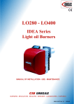
IDEA RANGE
LIGHT OIL BURNERS
LO280
LO400
Compying with
EMC 79/336/CEE
LV 73/23/CEE
Documentazione Tecnica CIB UNIGAS spa - Campodarsego (Padova - Italy)
M039134CB Rev. 1 12-06
TABLE OF CONTENTS
WARNINGS ...................................................................................................................................................... 3
PART I: INSTALLATION................................................................................................................................. 5
BURNERS CHARACTERISTICS .........................................................................................................................................5
Burner model identification................................................................................................................................................... 5
Technical Specifications .......................................................................................................................................................5
Overall dimensions (mm) .....................................................................................................................................................6
Performance curves ............................................................................................................................................................7
How to modify blast tube length (mod. LO400) ....................................................................................................................8
MOUNTING AND CONNECTIONS ....................................................................................................................................10
Fitting the burner to the boiler ............................................................................................................................................10
LIGHT OIL PIPING INSTALLATION DIAGRAM ................................................................................................................ 12
Pump operating principle ....................................................................................................................................................13
about the use of fuel pumps ...............................................................................................................................................14
Mounting of flexible light oil hoses...................................................................................................................................... 14
SETTING LO280 ................................................................................................................................................................15
Oil rate adjustment - Single stage burners .........................................................................................................................15
Priming the pump ...............................................................................................................................................................15
Choosing oil nozzles ..........................................................................................................................................................15
Oil rate adjustment - High-low flame burners .....................................................................................................................16
Priming the pump ...............................................................................................................................................................16
mod. LO280 Air rate setting ...............................................................................................................................................17
MOD. LO400 SETTINGS ...................................................................................................................................................18
Priming the pump ...............................................................................................................................................................18
Fuel rate adjustment ...........................................................................................................................................................18
Choosing the light oil nozzles .............................................................................................................................................18
First start and air rate setting (MOD. LO400) ..................................................................................................................... 20
SERVOCONTROL CAMS SETTING - Adjustment of cams microswitches .......................................................................21
LIGHT OIL PUMPS ............................................................................................................................................................ 22
mod. LO280 Pumps ...........................................................................................................................................................22
Pumps for mod. LO400 ......................................................................................................................................................23
ADJUSTING THE COMBUSTION HEAD .......................................................................................................................... 23
PART II: OPERATION................................................................................................................................... 24
OPERATION ...................................................................................................................................................................... 25
Single-stage burners ..........................................................................................................................................................25
Double-stage burners......................................................................................................................................................... 25
Burner’s control panel .......................................................................................................................................................25
PART III: MAINTENANCE............................................................................................................................. 26
ROUTINE OPERATIONS................................................................................................................................................... 26
Removing the combustion head .........................................................................................................................................26
Removing burner components plate .................................................................................................................................. 28
Assembling burner components plate ................................................................................................................................28
Removing the electrodes ....................................................................................................................................................29
DISASSEMBLY OF THE NOZZLE mod. LO280 ............................................................................................................... 29
Removing the nozzles LO400 ............................................................................................................................................30
Correct position of electrodes and combustion head .........................................................................................................31
Check the detection current ...............................................................................................................................................31
TROUBLESHOOTING ....................................................................................................................................................... 32
WIRING DIAGRAMS.......................................................................................................................................................... 33
SPARE PARTS ..................................................................................................................................................................41
APPENDIX..................................................................................................................................................... 43
2
WARNINGS
THIS MANUAL IS SUPPLIED AS AN INTEGRAL AND ESSENTIAL PART OF THE PRODUCT AND MUST BE DELIVERED
TO THE USER.
INFORMATION INCLUDED IN THIS SECTION ARE DEDICATED BOTH TO THE USER AND TO PERSONNEL FOLLOWING
PRODUCT INSTALLATION AND MAINTENANCE.
THE USER WILL FIND FURTHER INFORMATION ABOUT OPERATING AND USE RESTRICTIONS, IN THE SECOND SECTION OF THIS MANUAL. WE HIGHLY RECOMMEND TO READ IT.
CAREFULLY KEEP THIS MANUAL FOR FUTURE REFERENCE.
1)
GENERAL INTRODUCTION
2)
SPECIAL INSTRUCTIONS FOR BURNERS
z The equipment must be installed in compliance with the
z The burner should be installed in a suitable room, with ven-
regulations in force, following the manufacturer’s instructions, by qualified personnel.
z Qualified personnel means those having technical knowledge in the field of components for civil or industrial heating
systems, sanitary hot water generation and particularly service centres authorised by the manufacturer.
z Improper installation may cause injury to people and animals, or damage to property, for which the manufacturer
cannot be held liable.
z Remove all packaging material and inspect the equipment
for integrity.
In case of any doubt, do not use the unit - contact the supplier.
The packaging materials (wooden crate, nails, fastening devices, plastic bags, foamed polystyrene, etc), should not be left
within the reach of children, as they may prove harmful.
z Before any cleaning or servicing operation, disconnect the
unit from the mains by turning the master switch OFF, and/
or through the cut-out devices that are provided.
z Make sure that inlet or exhaust grilles are unobstructed.
z In case of breakdown and/or defective unit operation,
disconnect the unit. Make no attempt to repair the unit or
take any direct action.
Contact qualified personnel only.
Units shall be repaired exclusively by a servicing centre, duly
authorised by the manufacturer, with original spare parts.
Failure to comply with the above instructions is likely to impair
the unit’s safety.
To ensure equipment efficiency and proper operation, it is
essential that maintenance operations are performed by qualified personnel at regular intervals, following the manufacturer’s instructions.
z When a decision is made to discontinue the use of the
equipment, those parts likely to constitute sources of danger shall be made harmless.
z In case the equipment is to be sold or transferred to
another user, or in case the original user should move and
leave the unit behind, make sure that these instructions
accompany the equipment at all times so that they can be
consulted by the new owner and/or the installer.
z For all the units that have been modified or have options fitted then original accessory equipment only shall be used.
z This unit shall be employed exclusively for the use for
which it is meant. Any other use shall be considered as
improper and, therefore, dangerous.
The manufacturer shall not be held liable, by agreement or
otherwise, for damages resulting from improper installation,
use and failure to comply with the instructions supplied by the
manufacturer.
tilation openings complying with the requirements of the
regulations in force, and sufficient for good combustion.
z Only burners designed according to the regulations in force
should be used.
z This burner should be employed exclusively for the use for
which it was designed.
z Before connecting the burner, make sure that the unit
rating is the same as delivery mains (electricity, gas oil, or
other fuel).
z Observe caution with hot burner components. These are,
usually, near to the flame and the fuel pre-heating system,
they become hot during the unit operation and will remain
hot for some time after the burner has stopped.
When the decision is made to discontinue the use of the burner, the user shall have qualified personnel carry out the following operations:
a) Remove the power supply by disconnecting the power cord
from the mains.
b) Disconnect the fuel supply by means of the hand-operated
shut-off valve and remove the control handwheels from
their spindles.
Special warnings
z Make sure that the burner has, on installation, been firmly
secured to the appliance, so that the flame is generated
inside the appliance firebox.
z Before the burner is started and, thereafter, at least once a
year, have qualified personnel perform the following operations:
a) set the burner fuel flow rate depending on the heat input of
the appliance;
b) set the flow rate of the combustion-supporting air to obtain
a combustion efficiency level at least equal to the lower
level required by the regulations in force;
c) check the unit operation for proper combustion, to avoid
any harmful or polluting unburnt gases in excess of the
limits permitted by the regulations in force;
d) make sure that control and safety devices are operating
properly;
e) make sure that exhaust ducts intended to discharge the
products of combustion are operating properly;
f) on completion of setting and adjustment operations, make
sure that all mechanical locking devices of controls have
been duly tightened;
g) make sure that a copy of the burner use and maintenance
instructions is available in the boiler room.
z In case of repeated burner shut-downs, do not continue resetting the unit manually. Contact qualified personnel to
take care of such defects.
z The unit shall be operated and serviced by qualified personnel only, in compliance with the regulations in force.
3
WARNINGS
3) GENERAL INSTRUCTIONS DEPENDING ON FUEL
USED
3b) FIRING WITH GAS, LIGHT OIL OR OTHER FUELS
3a) ELECTRICAL CONNECTION
z The burner shall be installed by qualified personnel and in
z For safety reasons the unit must be efficiently earthed and
installed as required by current safety regulations.
z It is vital that all saftey requirements are met. In case of any
doubt, ask for an accurate inspection of electrics by qualified personnel, since the manufacturer cannot be held liable for damages that may be caused by failure to correctly
earth the equipment.
z Qualified personnel must inspect the system to make sure
that it is adequate to take the maximum power used by the
equipment shown on the equipment rating plate. In particular, make sure that the system cable cross section is adequate for the power absorbed by the unit.
z No adaptors, multiple outlet sockets and/or extension
cables are permitted to connect the unit to the electric
mains.
z An omnipolar switch shall be provided for connection to
mains, as required by the current safety regulations.
z The use of any power-operated component implies observance of a few basic rules, for example:
◆ do not touch the unit with wet or damp parts of the body
and/or with bare feet;
◆ do not pull electric cables;
◆ do not leave the equipment exposed to weather (rain,
sun, etc.) unless expressly required to do so;
◆ do not allow children or inexperienced persons to use
equipment;
z The unit input cable shall not be replaced by the user.
In case of damage to the cable, switch off the unit and contact
qualified personnel to replace.
When the unit is out of use for some time the electric switch
supplying all the power-driven components in the system (i.e.
pumps, burner, etc.) should be switched off.
GENERAL
compliance with regulations and provisions in force; wrong
installation can cause injuries to people and animals, or
damage to property, for which the manufacturer cannot be
held liable.
z Before installation, it is recommended that all the fuel supply system pipes be carefully cleaned inside, to remove
foreign matter that might impair the burner operation.
z Before the burner is commissioned, qualified personnel
should inspect the following:
a) the fuel supply system, for proper sealing;
b) the fuel flow rate, to make sure that it has been set based
on the firing rate required of the burner;
c) the burner firing system, to make sure that it is supplied for
the designed fuel type;
d) the fuel supply pressure, to make sure that it is included in
the range shown on the rating plate;
e) the fuel supply system, to make sure that the system
dimensions are adequate to the burner firing rate, and that
the system is equipped with all the safety and control devices required by the regulations in force.
z When the burner is to remain idle for some time, the fuel
supply tap or taps should be closed.
SPECIAL INSTRUCTIONS FOR USING GAS
Have qualified personnel inspect the installation to ensure
that:
a) the gas delivery line and train are in compliance with the
regulations and provisions in force;
b) all gas connections are tight;
c) the boiler room ventilation openings are such that they
ensure the air supply flow required by the current regulations, and in any case are sufficient for proper combustion.
z Do not use gas pipes to earth electrical equipment.
z Never leave the burner connected when not in use. Always
shut the gas valve off.
z In case of prolonged absence of the user, the main gas
delivery valve to the burner should be shut off.
Precautions if you can smell gas
a) do not operate electric switches, the telephone, or any
other item likely to generate sparks;
b) immediately open doors and windows to create an air flow
to purge the room;
c) close the gas valves;
d) contact qualified personnel.
z Do not obstruct the ventilation openings of the room where
gas appliances are installed, to avoid dangerous conditions
such as the development of toxic or explosive mixtures.
WARNINGS
4
PART I: INSTALLATION
BURNERS CHARACTERISTICS
Burner model identification
Burners are identified by burner type and model. Burner model identification is described as follow.
Type LO400 Model
G-.
TN.
S.
*.
A.
(1)
(2)
(3)
(4)
(5)
(6)
(1)
(2)
BURNER TYPE
FUEL
(3)
OPERATION Available versions
(4)
BLAST TUBE
(5)
(6)
DESTINATION COUNTRY
BURNER VERSION
LO280 - LO400
GLight oil
A - Biodiesell
TN - Single stage
AB - Double stage
M - Modular
S - Standard
L - Long
* - destination country (see data plate)
A - Standard
Y - Special
M -Hydraulic jack
Technical Specifications
BURNERS
Output
min. - max. kW
Light oil rate
min.- max. kg/h -
Fuel
LO280
G-.TN.x.xx.A
LO280
G-.AB.x.xx.A
115 - 310
70 - 310
9.6 - 26
5.8 - 26
Light oil
Light oil
230V
Power supply
50Hz
kW
0.25
0.25
Total power consumption
W
0.55
0.55
Weight
kg
42
42
Single stage
éDouble stage
Electric motor
Operation
Operating temperature
°C
Storage Temperature
°C
-10 ÷ +50
-20 ÷ +60
Intermittent
Working service*
LO400
G-.TN.x.xx.A
LO400
G-.AB.x.xx.A
min.-max.kW
195 - 420
115 - 420
min. - max. kg/h
16 - 35
10 - 35
BURNERS
Output
Light oil rate
Fuel
Light oil
Light oil
230V
Power supply
50Hz
Electric motor
kW
0.37
0.37
Total power consumption
W
0.67
0.67
Weight
Kg
Operation
Operating temperature
°C
Storage Temperature
°C
42
42
Single stage
éDouble stage
-10 ÷ +50
-20 ÷ +60
Intermittent
Working service*
*NOTE ON THE BURNER WORKING SERVICE: for safety reasons, one controlled shutdown must take place every 24
hours.
WARNING: if fuel used is BIODIESEL, some components must be replaced. Please contact our Technical Department for further details.
PART I: INSTALLATION
5
6
PART I: INSTALLATION
O
AS*
AL*
732.5 877.5
748 877.5
T
B
BS*
162.5
178
Fig. 4
Y
.As far as modifying the blast tube for mod. LO400, see page 8.
*S = standard blast tube
*L = long blast tube
LO280
LO400
C
A
OVERALL DIMENSIONS (mm)
L
G
BL*
307.5
307.5
X
C
570
570
F
396
396
G
108
125
F
H
128
164
K1
215
215
K2
223
223
L
348
348
M
N
M
M10
M10
H
O max.
O min.
P
K1
N Omin Omax P
219 131
179
155
219 131
179
155
X
492
491
Y
108
144
Fig. 5: Boiler’s drilling plate and burner’s flange
P
O max.
O min.
K2
Performance curves
LO280 High-Low flame
BACK PRESSURE IN
CCOMBUSTION CHAMBER mbar
LO280 Single stage
6
6
5
5
4
4
3
3
2
2
1
0
100
1
150
200
250
300
350
0
50
100
150
250
300
Fig. 7
LO400 High-Low flame
LO400 Single stage
8
7
6
9
8
7
6
5
4
3
2
1
0
-1
100
5
4
3
2
1
0
-1
150
200
250
350
kW
Fig. 6
BACK PRESSURE IN
CCOMBUSTION CHAMBER mbar
200
kW
300
350
400
450
150
200
250
kW
Fig. 8
300
350
400
450
kW
Fig. 9
PART I: INSTALLATION
7
How to modify blast tube length (mod. LO400)
To modify blast tube length please read the following instructions.
1 Remove combustion head (See “Removing the combustion head” - Part III of this user’s manual).
2 Remove the flanged piece T by removing the 4 socket head screws VTF (Fig. 10).
3 Remove the 4 screws which hold the blast tube to the flanged piece (Fig. 2).
4 Extract the blast tube from the flanged piece and assemble it in the other way round as shown in pictures Fig. 12 and Fig.
13. Now fasten the two pieces using the same screws (Fig. 14).
5 Assemble the whole piece to the burner by caring attention to the indication in picture Fig. 15.
T
VTF
8
Fig. 10
Fig. 11
Fig. 12 - Short blast tube
Fig. 13 - Long blast tube
Fig. 14
Fig. 15
PART I: INSTALLATION
If you modify the blast tube length you have to modify also the combustion head length by reading the following instructions:
1 Loosen the light oil feeding pipes connected to the nozzle-holder by using two spanners size 22 and 10 (Fig. 16).
2 Adjust cables length by pulling them very slightly as shown in Fig. 17.
3 Loosen the screw VA which tights the rod A (Fig. 18) and shift backward the flange as shown.
4 Tight the screw in the backward hole on the rod, see picture Fig. 19.
5 Fix the two extensions (supplied along with the burner inside the accessories carton box) on the light oil feeding pipes (Fig.
20) and tight them by using two spanners size 13 and 10 (Fig. 21). Fix the extensions to the nozzle holder by using two
spanners size 22 and 10 (Fig. 16).
6
Assemble again the combustion head (See “Removing the combustion head” - Part III of this user’s manual).
22
10
Fig. 17
Fig. 16
VA
A
Fig. 19
Fig. 18
Fig. 20
13
10
Fig. 21
PART I: INSTALLATION
9
MOUNTING AND CONNECTIONS
Packing
The burners are despatched in packages of dimensions 795 x 550 x 490 mm (W x H x D).
Packing cases of this kind are affected by humidity; the maximum number of cases to be stacked is indicated outside the
packing .
The following are placed in each packing case:
1
burner;
2
light oil flexible hoses;
1
light oil filter;
1
gasket to be inserted between the burner and the boiler;
1
envelope containing this manual.
To get rid of the burner’s packing and in the event of scrapping of the latter, follow the procedures laid down by current laws on
disposal of materials.
ATTENZIONE: LEGGERE SCRUPOLOSAMENTE LE AVVERTENZE RIPORTATE ALL’INIZIO DEL MANUALE.
Fitting the burner to the boiler
To perform the installation, proceed as follows:
1 fix 4 holes on the boiler’s door, according to the burner’s drilling plate described on
paragraph “Overall dimensions”;
2 place the gasket on the burner’s flange;
3 install the burner into the boiler;
4 fix the burner to the stud bolt, by means of the fixing nuts, according to Fig. 22.
5 After fitting the burner to the boiler, ensure that the gap between the blast tube and
the refractory lining is sealed with appropriate insulating material (ceramic fibre
cord or refractory cement).
Key
1 Burner
2 Fixing nut
3 Washer
4 Sealing gasket
5 Stud bolt
7 Blast tube
10
Fig. 22
PART I: INSTALLATION
ELECTRICAL WIRING
ATTENTION: PLEASE READ CAREFULLY THE “WARNINGS” CHAPTER, AT THE BEGINNIG OF THIS MANUAL.
Identification of linking connectors
HIGH/LOW flame connector
(CONN-TAB, ) - mod. LO400
Fig. 23
Burner power supply connector
(CONN-LINEA, Fig. 24, )
Fig. 24
IMPORTANT: before operating the burner, be sure all connectors are linked as indicated in the diagrams.
Make the electric connections following the diagrams below.
WARNING: the burner is fitted with a bridge between terminals T6 and T8 on CN2-TAB connector
(external side link, male connector); remove this bridge before thermostat connection.
Fig. 25: Single stage burners
Key
C1-C2
Fig. 26: High - Low flame burners
LAF
Time counter
LB
Burner in high flame signalling lamp (high-low flame and progressive versions only)
Burner lockout signalling lamp
CONN-LINEAConnectors on electrical board LBF
CONN-TABConnectors on electrical board N
Burner in low flame signalling lamp (high-low flame and progressive versions only)
F1-F3
Thermostats or pressure switches group
Fuses
ST
Neutral
IL
Line switch for burner’s auxiliaries TAB
High-Low flame thermostat
IM
Fan motor line switch
Boiler safety thermostat
L
Phase
TS
PART I: INSTALLATION
11
LIGHT OIL PIPING INSTALLATION DIAGRAM
PLEASE READ CAREFULLY THE “WARNINGS” CHAPTER AT THE BEGINNIGN OF THIS MANUAL
From tank
To tank
Fig. 27
Key
1 Burner
2 Flexible hoses (fitted)
3 Light oil filter (fitted)
4 Automatic interceptor (*)
5 One-way valve (*)
6 Gate valve
7 Quick-closing gate-valve (not in vicinity of tank or boiler)
12
PART I: INSTALLATION
(*) Only for installations with gravity, siphon or forced circulation feed systems. If the device installed
is a solenoid valve, a timer must be installed to
delay the valve closing.
The direct connection of the device without a timer
may cause pump breaks.
Pump operating principle
In the burners, the mixture bertween oil and air, to perform a clean and efficient combustion, is activated by atomization of oil
into very small particles. This process is achieved making oil passing through the nozzle at a determined pressure
The pump’s main function is to transfer oil from the tank to the nozzle in the desired quantity and pressure. To adjust this pressure, pumps are provided with a pressure regulator (except for some models for which a separate regulating valve si provided).
Other pumps are provided with two pressure regulators: one for the high and one for low pressure (in tow-stage systems with
one nozzle).
These pumps can be installed both into single-pipe and double-pipe systems.
Single-pipe system: a single pipe drives the oil from the tank to the pump’s inlet. Then, from the pump, the pressurised oil is
driven to the nozzle: a part comes out from the nozzle while the othe part goes back to the pump. In this system, the by-pass
pulg, if provided, must be removed and the optional return port, on the pump’s body, must be sealed by steel plug and washer.
Double-pipe system: as for the single pipe system, a pipe that connects the tank to the pump’s inlet is used besides another
pipe that connects the pum’s return port to the tank, as well. The excess of oil goes back to the tank: this installation can be considered self-bleeding. If provided, the inside by-pass plug must be installed to avoid air and fuel passing through the pump.
Burners come out from the factory provided for double-stage systems. They can be suited for single-pipe system (recommended in the case of gravity feed) as decribed before.
Bleed
Bleeding in two-pipe operation is automatic : it is assured by a bleed flat on the piston. In one-pipe operation, the plug of a pressure gauge port must be loosened until the air is evacuated from the system.
As far as the pipes installation, refer to the following values, considering as well, the plant’s needs.
Syphon twin pipe feed
Twin pipe suction feed
Fig. 28
Fig. 29
SUNTEC AL65 - AS47 - AT2 45
SUNTEC AL65 - AS47 - AT2 45
H (m)
0
0,5
1
2
3
4
L (m)
ø6
14
16
18
22
25
29
ø8
49
55
61
73
85
96
ø10
123
136
150
150
150
150
H (m)
ø12
150
150
150
150
150
150
0
0,5
1
2
3
4
PART I: INSTALLATION
L (m)
ø6
14
12
10
7
3
0
ø8
49
44
38
26
13
1
ø10
123
110
96
66
13
1
ø12
150
150
150
140
75
15
13
about the use of fuel pumps
z
z
z
z
z
z
z
z
Make sure that the by-pass plug is not used in a single pipe installation, because the fuel unit will not function properly and
damage to the pump and burner motor could result.
Do not use fuel with additives to avoid the possible formation over time of compounds which may deposit between the gear
teeth, thus obstructing them.
After filling the tank, wait before starting the burner. This will give any suspended impurities time to deposit on the bottom of
the tank, thus avoiding the possibility that they might be sucked into the pump.
On initial commissioning a "dry" operation is foreseen for a considerable length of time (for example, when there is a long
suction line to bleed). To avoid damages inject some lubrication oil into the vacuum inlet.
Care must be taken when installing the pump not to force the pump shaft along its axis or laterally to avoid excessive wear
on the joint, noise and overloading the gears.
Pipes should not contain air pockets. Rapid attachment joint should therefore be avoided and threaded or mechanical seal
junctions preferred. Junction threads, elbow joints and couplings should be sealed with removable sg component. The number of junctions should be kept to a minimum as they are a possible source of leakage.
Do not use PTFE tape on the suction and return line pipes to avoid the possibility that particles enter circulation. These
could deposit on the pump filter or the nozzle, reducing efficiency. Always use O-Rings or mechanical seal (copper or aluminium gaskets) junctions if possible.
Filter must be thoroughly cleaned at least once in a season to ensure correct working of the fuel unit. To remove the filter,
unscrew the four screws on the cover. When reassemble, make sure that the filter is mounted with the feet toward the pump
body. If the gasket between cover and pump housing should be damaged, it must be replaced. An external filter should
always be installed in the suction line upstream of the fuel unit.
Mounting of flexible light oil hoses
To connect the flexible hoses to the pump, proceed as follows.
1 Remove burner’s cover.
mod. LO280
A
B
Fig. 30
2
3
4
Fig. 31
mod. LO400
D
D
F
F
Fig. 32
Remove the light oil pump delivery and return line plugs.
Screw the rotating nut D of the two flexible hoses F on the pump being careful to avoid inverting the delivery and return lines.
Fix the flexible hoses as shoewed on Fig. 33
Fig. 33
5
Replace burner’s cover.
WARNING: if fuel used is BIODIESEL, some components must be replaced. Please contact our Technical Department for further details.
14
PART I: INSTALLATION
SETTINGS LO280
Oil rate adjustment - Single stage burners
Priming the pump
Before carrying out the adjustment it is necessary to start up the fuel pump, proceeding as follows:
Prior to start up the burner, make sure that the return pipe to the tank is not obstructed. Any obstruction would
cause the pump seal to break.
Start the burner, light up the photoresistor after the opening of the solenoid valve and escape the air from the pressure port.
The fuel flow rate is set choosing a properly dimensioned nozzle and setting the inlet pressure on the pump (see the hydraulic
diagram in Fig. 34
To choose the correct nozzle refer to table Tab. 1; for setting of the pump pressure, see pag. 23.
Note: all pumps are set to 12 bar. The nozzle rate must be higher than the rate referred to the minimum burner
output.
Choosing oil nozzles
Key
EVG Light oil solenoid valve
M
Manometer
P
Pump (see chapter “LIGHT OIL PUMPS”)
Fig. 34
M
P
EVG
Tab. 1 - Choice of the oil nozzle - Single stage burners
NOZZLE
PUMP PRESSURE (bar)
6
7
8
9
G.P.H.
10
11
12
13
14
kg/h
1,35
3,97
4,29
4,59
4,86
5,13
5,38
5,62
5,85
6,07
1,50
4,41
4,77
5,10
5,41
5,70
5,98
6,24
6,50
6,74
1,65
4,85
5,24
5,61
5,95
6,27
6,57
6,87
7,15
7,42
1,75
5,15
5,56
5,95
6,31
6,65
6,97
7,28
7,58
7,87
2,00
5,88
6,36
6,80
7,21
7,60
7,97
8,32
8,66
8,99
2,25
6,62
7,15
7,64
8,11
8,55
8,96
9,36
9,74
10,11
2,50
7,36
7,95
8,49
9,01
9,50
9,96
10,40
10,83
11,24
3,00
8,83
9,53
10,19
10,81
11,40
11,95
12,48
12,99
13,48
3,50
10,30
11,12
11,89
12,61
13,29
13,94
14,56
15,16
15,73
4,00
11,77
12,71
13,59
14,41
15,19
15,94
16,64
17,32
17,98
4,50
13,24
14,30
15,29
16,22
17,09
17,93
18,72
19,49
20,23
5,00
14,71
15,89
16,99
18,02
18,99
19,92
20,81
21,65
22,47
5,50
16,18
17,48
18,69
19,82
20,89
21,91
22,89
23,82
24,72
6,00
17,65
19,07
20,39
21,62
22,79
23,90
24,97
25,99
26,97
6,50
19,13
20,66
22,08
23,42
24,69
25,90
27,05
28,15
29,21
PART I: INSTALLATION
15
Oil rate adjustment - High-low flame burners
Priming the pump
Before carrying out the adjustment it is necessary to start up the fuel pump, proceeding as follows:
Prior to start up the burner, make sure that the return pipe to the tank is not obstructed. Any obstruction would
cause the pump seal to break.
Start the burner, light up the photoresistor after the opening of the solenoid valve and escape the air from the pressure port.
The light oil flow rate is adjusted choosing a nozzle of proper dimensions and setting the inlet pump pressure.
To choose the nozzle refer to the table below.
Setting the light oil pump
Adjust the ignition stage of the pump, to a pressure value of 8 - 10 bar. After 10”, the safety device switch to the second stage.
The pump setting must be fixed to 24 bar, by means of the adjusting screw (see chapter “LIGHT OIL PUMPS”).
NOTE: The nozzle oil rate at a pressure of 8 bar, must be greather than the oil rate at the minimum output.
Regulator
high flame
Regulator
low flame
low flame: 8÷10 bar
high flame: 24 bar
Tab. 2 - Choice of the oil nozzle - High-low flame burners
NOZZLE
G.P.H.
0,40
0,50
0,60
0,65
0,75
0,85
1,00
1,10
1,20
1,25
1,35
1,50
1,65
1,75
2,00
2,25
2,50
3,00
3,50
4,00
4,50
16
8
9
10
11
12
13
14
1,36
1,70
2,04
2,21
2,55
2,89
3,40
3,74
4,08
4,25
4,59
5,10
5,61
5,95
6,80
7,64
8,49
10,19
11,89
13,59
15,29
1,44
1,80
2,16
2,34
2,70
3,06
3,60
3,96
4,32
4,50
4,86
5,41
5,95
6,31
7,21
8,11
9,01
10,81
12,61
14,41
16,22
1,52
1,90
2,28
2,47
2,85
3,23
3,80
4,18
4,56
4,75
5,13
5,70
6,27
6,65
7,60
8,55
9,50
11,40
13,29
15,19
17,09
1,59
1,99
2,39
2,59
2,99
3,39
3,98
4,38
4,78
4,98
5,38
5,98
6,57
6,97
7,97
8,96
9,96
11,95
13,94
15,94
17,93
1,66
2,08
2,50
2,70
3,12
3,54
4,16
4,58
4,99
5,20
5,62
6,24
6,87
7,28
8,32
9,36
10,40
12,48
14,56
16,64
18,72
1,73
2,17
2,60
2,82
3,25
3,68
4,33
4,76
5,20
5,41
5,85
6,50
7,15
7,58
8,66
9,74
10,83
12,99
15,16
17,32
19,49
1,80
2,25
2,70
2,92
3,37
3,82
4,49
4,94
5,39
5,62
6,07
6,74
7,42
7,87
8,99
10,11
11,24
13,48
15,73
17,98
20,23
PUMP PRESSURE (bar)
15
16
17
18
kg/h
1,86
1,92
1,98
2,04
2,33
2,40
2,48
2,55
2,79
2,88
2,97
3,06
3,02
3,12
3,22
3,31
3,49
3,60
3,71
3,82
3,95
4,08
4,21
4,33
4,65
4,80
4,95
5,10
5,12
5,29
5,45
5,61
5,58
5,77
5,94
6,12
5,82
6,01
6,19
6,37
6,28
6,49
6,69
6,88
6,98
7,21
7,43
7,64
7,68
7,93
8,17
8,41
8,14
8,41
8,67
8,92
9,30
9,61
9,91
10,19
10,47
10,81
11,14
11,47
11,63
12,01
12,38
12,74
13,96
14,41
14,86
15,29
16,28
16,82
17,33
17,84
18,61
19,22
19,81
20,39
20,94
21,62
22,29
22,93
PART I: INSTALLATION
19
20
21
22
23
24
25
2,09
2,62
3,14
3,40
3,93
4,45
5,24
5,76
6,28
6,54
7,07
7,85
8,64
9,16
10,47
11,78
13,09
15,71
18,33
20,94
23,56
2,15
2,69
3,22
3,49
4,03
4,57
5,37
5,91
6,45
6,71
7,25
8,06
8,86
9,40
10,74
12,09
13,43
16,12
18,80
21,49
24,17
2,20
2,75
3,30
3,58
4,13
4,68
5,50
6,06
6,61
6,88
7,43
8,26
9,08
9,63
11,01
12,39
13,76
16,51
19,27
22,02
24,77
2,25
2,82
3,38
3,66
4,23
4,79
5,63
6,20
6,76
7,04
7,61
8,45
9,30
9,86
11,27
12,68
14,09
16,90
19,72
22,54
25,35
2,30
2,88
3,46
3,74
4,32
4,90
5,76
6,34
6,91
7,20
7,78
8,64
9,51
10,08
11,52
12,96
14,40
17,28
20,16
23,04
25,92
2,35
2,94
3,53
3,83
4,41
5,00
5,88
6,47
7,06
7,36
7,94
8,83
9,71
10,30
11,77
13,24
14,71
17,65
20,60
23,54
26,48
2,40
3,00
3,60
3,90
4,50
5,11
6,01
6,61
7,21
7,51
8,11
9,01
9,91
10,51
12,01
13,51
15,02
18,02
21,02
24,02
27,03
mod. LO280 Air rate setting
z
Single stage burners
z
loosen VR screw.
move the ID index along the graduated
slot towards + or -, in order to increase
or decrease the air flow-rate, according
to the required combustion values.
asten the VR screw again.
z
z
ID
VR
Fig. 35
z
Double stage burners
Servocontrol cams adjustement
.
.Air damper position is set by means of the servocontrol cams. As for the setting, refer to the next table
The STA4.5B0.37 is not provided with the manual contrl for the air damper. The cams adjustement must be performed by
means of a screwdriver acting on the VS screw placed inside the cam. During the first setting, set the cam III between the
cams I and II. Then, passing from the low to high flame stage, or viceversa, change the setting according to the flame composition: if cam III is too near to the low flame position (cam II), flue gas can take place, because there is more fuel than air; if cam III
is too near to high flame (cam I), the flame could fade because of too much air.
Fig. 36 - Berger STA4.5B0.37/63N30L
VS
I
II
III
BERGER
STA4.5B0.37/6..
I
High flame
II
Low flame - stand by - ignition
III
EVG2 opening (2nd nozzle)
PART I: INSTALLATION
17
MOD. LO400 SETTINGS
Priming the pump
Before carrying out the adjustment it is necessary to start up the fuel pump, proceeding as follows:
Prior to start up the burner, make sure that the return pipe to the tank is not obstructed. Any obstruction would
cause the pump seal to break.
Start the burner, light up the photoresistor after the opening of the solenoid valve and escape the air from the pressure port.
Fuel rate adjustment
The fuel rate is setting choosing properly sized nozzles and adjusting the fuel pressure at the pump inlet (see the diagram Fig.
37 and Fig. 38). To choose the nozzles refer to Tab. 3b and Tab. 1b; for pump pressure regulation see on pag. 23. For further
information on fuel pump see also the appendix.
Note: all pumps are set to 12 bar. The nozzle rate must be higher than the rate referred to the minimum burner
output.
Fig. 37 - Single stage burners
Key
EV
Fuel solenoid valve
EVG1
Fuel solenoid valve - low flame
EVG2
Fuel solenoid valve - high flame (only hi-lo
flame burners)
M
Manometer
P
Pump
EVG
Fig. 38 - Double stage burners
EVG2
P
M
EVG1
Choosing the light oil nozzles
Tab. 3a - Single-stage LO400
10
NOZZLE (G.P.H.)
4,00
4,50
5,00
5,50
6,00
6,50
7,00
7,50
8,30
9,50
18
15,19
17,09
18,99
20,89
22,79
24,69
26,59
28,49
31,53
36,09
PUMP PRESSURE (bar)
12
FUEL RATE kg/h
16,64
18,72
20,81
22,89
24,97
27,05
29,13
31,21
34,54
39,53
PART I: INSTALLATION
14
17,98
20,23
22,47
24,72
26,97
29,21
31,46
33,71
37,30
42,70
Tab. 3b - Double-stage LO400
RATE
OUTPUT
PUMP PRESSURE
kg
kcal/h
kW
10bar
12bar
14bar
30
306.300
356
3.50+4.50
3.00+4.00
3.00+3.50
35
357.350
416
4.00+5.00
3.50+5.00
3.50+4.00
40
408.400
475
4.50+6.00
4.00+5.50
4.00+5.00
45
459.450
534
5.00+6.50
4.50+6.00
4.00+6.00
50
510.500
594
5.50+7.50
5.00+7.00
4.50+6.50
PART I: INSTALLATION
19
First start and air rate setting (MOD. LO400)
Single stage burners
Set the air rate working on the screw VBS (Fig. 39); screw to
decrease the air rate or unscrew to increase it.
Two-stage burners
z The air flow can be adjusted using the air damper servo-con-
trol cams as follows.
z Remove the burner's cover cover.
VBS
z Remove the servo-control's cover.
z Start the burner and let it burn at low flame (remove the bri-
dge between Terminals T6 and T8).
z Adjust the air flow in low flame by working on the appropriate
cam (Fig. 42).
z Prime the second nozzle using the following procedure:
Fig. 39
♦ Start the burner
♦ When the flame appears press the P1 button (Fig. 40) for a
few seconds to fill the second nozzle pipe;
z The cycle continues, and if the TAB
thermostat is connected, the flame control apparatus brings the burner to high
flame. If the TAB thermostat is not connected, bridge Terminals T6 and T8 on the connector (see “Identification of linking
connectors” on page 11 and “Connectors layout on printed
board” on page 41). Adjust the air flow at high flame by
working on the appropriate cam.
z The cam that triggers the opening of the 2nd stage fuel valve
(valve EVG2) must be set in an intermediate position
between the other two cams.
z Replace the cover on the servo-control.
z Replace the burner's cover.
P1
Fig. 40 - Second nozzle’s ignition pushbutton on double stage
burners
Connections for pressure measurement
Combustion chamber pressure port
Fan air pressure port
Fig. 41
20
PART I: INSTALLATION
SERVOCONTROL CAMS SETTING - Adjustment of cams microswitches
Refer to Tab. 4 for cams functions.
I
II
III
VS
Fig. 42 - Berger STA4.5B037/4
Air damper position is set by means of the servocontrol cams. As for the setting, refer to the next table.
The STA4.5B0.37 is not provided with the manual control for the air damper. The cams adjustement must be performed by
means of a screwdriver acting on the VS screw placed inside the cam. During the first setting, set the cam III inbetweens the
cam I and II. Then, passing from the low to high flame stage, or viceversa, change the setting according to the flame composition: if cam III is too near to the low flame position (cam II), flue gas can take place, because there is more fuel than air; if cam III
is too near to low flame (cam I), the flame could be turned off because of too much air.
Tab. 4
BERGER
STA4.5BO.37
Air adjustment in high flame cam
I
Air adjustment in low flame - Stand-by - Ignition cam
II
Auxiliary cam for the opening consent to the second fuel valve
III
PART I: INSTALLATION
21
LIGHT OIL PUMPS
mod. LO280 Pumps
Pump Suntec AS47 A
Viscosity
Fuel temperature
Maximum inlet pressure
2 - 12 mm²/s (cSt)
0 - 60 °C into the pump
14 bar max.
Return pressure
Rated speed
- 0,45 barto avoid the separation
between air and oil
2 bar max.
3600 rpm max.
Fig. 43
Pump Suntec AT2 45A
Viscosity range
Oil temperature
Inlet pressure
2 ÷ 12 (cSt) mm2/s
60 °C max
2 bar max.
Return pressure
Rated speed
- 0,35 barto avoid the separation
between air and oil
2 bar max.
3600 rpm
Fig. 44
Keys for Suntec AS47 A pump
1
Pressure governor
2
Manometer
3
Vacuum gauge
4
Solenoid valve
5
Nozzle
7
Suction
8
Return
22
Keys for Suntec A T2 45A pump
1
Low pressure regulation (first stage)
2
Manometer
3
Vacuum gauge
4
Light oil solenoid valve
4a High-low pressure solenoid valve
5
To nozzle
6
High pressure regulation (second stage)
7
Suction
8
Return (with internal by-pass plug)
PART I: INSTALLATION
Pumps for mod. LO400
Pump Suntec AL65
Viscosity range
Oil temperature
Inlet pressure
2 ÷ 12 (cSt) mm2/s
0 - 60 °C in the pump
2 bar max.
- 0,45 barto avoid the separation
between air and oil
2 bar max.
3600 rpm
Minimum inlet pressure
Return pressure
Rated speed
1
2
3
4
5
6
suction
return and internal by-pass plug
nozzle outlet
pressure gauge port
vacuum gauge port
pressure adjustement
Fig. 45
ADJUSTING THE COMBUSTION HEAD
The burner is set in the factory with the combustion head in the "MAX" position, corresponding to the maximum power (combustion head all-forward). To operate the burner at a lowest strenght, progressively shift back the combustion head, toward the
"MIN" position, rotating the VRT screw clockwise (Fig. 47).
MIN
MIN
VRT
VRT
MAX
MAX
Fig. 46 LO280
Fig. 47 LO400
PART I: INSTALLATION
23
PART II: OPERATION MANUAL
LIMITATIONS OF USE
THE BURNER IS AN APPLIANCE DESIGNED AND CONSTRUCTED TO OPERATE ONLY AFTER BEING CORRECTLY
CONNECTED TO A HEAT GENERATOR (E.G. BOILER, HOT AIR GENERATOR, FURNACE, ETC.), ANY OTHER USE IS TO
BE CONSIDERED IMPROPER AND THEREFORE DANGEROUS.
THE USER MUST GUARANTEE THE CORRECT FITTING OF THE APPLIANCE, ENTRUSTING THE INSTALLATION OF IT
TO QUALIFIED PERSONNEL AND HAVING THE FIRST COMMISSIONING OF IT CARRIED OUT BY A SERVICE CENTRE
AUTHORISED BY THE COMPANY MANUFACTURING THE BURNER.
A FUNDAMENTAL FACTOR IN THIS RESPECT IS THE ELECTRICAL CONNECTION TO THE GENERATOR’S CONTROL
AND SAFETY UNITS (CONTROL THERMOSTAT, SAFETY, ETC.) WHICH GUARANTEES CORRECT AND SAFE FUNCTIONING OF THE BURNER.
THEREFORE, ANY OPERATION OF THE APPLIANCE MUST BE PREVENTED WHICH DEPARTS FROM THE INSTALLATION OPERATIONS OR WHICH HAPPENS AFTER TOTAL OR PARTIAL TAMPERING WITH THESE (E.G. DISCONNECTION, EVEN PARTIAL, OF THE ELECTRICAL LEADS, OPENING THE GENERATOR DOOR, DISMANTLING OF PART OF
THE BURNER).
NEVER OPEN OR DISMANTLE ANY COMPONENT OF THE MACHINE.
OPERATE ONLY THE MAIN SWITCH, WHICH THROUGH ITS EASY ACCESSIBILITY AND RAPIDITY OF OPERATION
ALSO FUNCTIONS AS AN EMERGENCY SWITCH, AND ON THE RESET BUTTON.
IN THE EVENT OF REPEATED LOCKOUTS, DO NOT PERSIST WITH THE RESET BUTTON AND CONTACT QUALIFIED
PERSONNEL WHO WILL PROCEED TO ELIMINATE THE MALFUNCTION.
WARNING: DURING NORMAL OPERATION THE PARTS OF THE BURNER NEAREST TO THE GENERATOR (COUPLING
FLANGE) CAN BECOME VERY HOT, AVOID TOUCHING THEM SO AS NOT TO GET BURNT.
24
PART II: OPERATION MANUAL
FUNCIONAMIENTOOPERATION
Single-stage burners
z
z
z
z
z
z
Turn on the burner using the switch A on the control panel (Fig. 48: the control panel of the single stage burner is only provided with the power switch and the fuse).
Make sure that the apparatus is not in shutdown condition and if so, release by using the release button S on the burner
cover (see Fig. 49).
Make sure that the set of thermostats (or pressure-switches) triggers burner operation.
The burner starting cycle begins and the apparatus starts the burner fan while the ignition transformer switches on at the
same time.
At the end of pre-ventilation, the fuel solenoid valve receives input and the burner switches on.
The ignition transformer remains switched on for a few seconds after the ignition of the flame (post-ignition time) after which
it is disconnected from the circuit.
Double-stage burners
z
z
z
z
z
z
z
Turn on the burner using the switch A on the control panel (Fig. 48).
Make sure that the apparatus is not in shutdown condition and if so, release by using the release button S on the burner
cover (see Fig. 49).
Make sure that the set of thermostats (or pressure-switches) triggers burner operation.
The burner starting cycle begins and the apparatus starts the burner fan while the ignition transformer switches on at the
same time; pre-ventilation lasts for 13 or 25 seconds depending on the apparatus provided with the burner.
At the end of pre-ventilation, the fuel solenoid valve (1st stage, EVG1) receives input as signalled by the illumination of the
signal light H on the control panel and the burner starts.
The ignition transformer remains switched on for a few seconds after the ignition of the flame (post-ignition time), after
which it is disconnected from the circuit and the corresponding signal light switches off.
In this way, the burner is lit at low flame; after 5 or 15 seconds (depending on the apparatus installed) two-stage operation
begins and the burner is either automatically brought to high flame (light G on) or remains burning at low flame (light H on)
depending on the requests received from the system.
Burner’s control panel
Keys
A
E
B
C
D
A
G
H
F
Main switch
B
High flame lamp
C
Low flame lamp
D
Ignition transformer ligh
E
Lockout signalling lamp
F
Fuse
G
High flame solenoid valve operation light
H
Low flame solenoid valve operation light
S
Reset pushbutton (Fig. 49)
Fig. 48
S
Fig. 49
PART II: OPERATION MANUAL
25
PART III: MAINTENANCE MANUAL
At least once a year carry out the maintenance operations listed below. In the case of seasonal servicing, it is recommended to
carry out the maintenance at the end of each heating season; in the case of continuous operation the maintenance is carried out
every 6 months.
WARNING: All operations on the burner must be carried out with the mains disconnected!
PLEASE, READ CAREFULLY “WARNINGS” CHAPTER, AT THE BEGINNING OF THIS MANUAL.
ROUTINE OPERATIONS
z
z
z
z
z
z
Inspection and cleaning of the light oil filter cartdrige; replace it if necessary.
Check the overall condition of the flexible light oil hoses and make sure there are no signs of leakage;
Inspection and cleaning of the filter inside the light oil pump: filter must be thoroughly cleaned at least once in a season to
ensure correct working of the fuel unit. To remove the filter, unscrew the four screws on the cover. When reassemble, make
sure that the filter is mounted with the feet toward the pump body. If the gasket between cover and pump housing should be
damaged, it must be replaced.
Disassembly, inspection and cleaning of the combustion head. Respect the measurements listed on pag. 31 carefully
during re-assembly.
Inspection and cleaning of ignition electrodes (pag. 29) and respective ceramic insulators: clean, adjust, and replace if
necessary.
Disassemble and clean the light oil nozzles (pag. 29).
IMPORTANT: cleaning must be performed using solvent, not metal tools!
At the end of maintenance operations after first reassembling the burner, light the flame and check its shape, replacing the nozzle whenever a questionable flame shape appears. Whenever the burner is used intensely, we recommend preventively replacing the nozzle at the start of each heating season;
z Inspect and thoroughly clean the flame detection photoresistor and replace if necessary. In case of doubt, check the detection current after first starting the burner by following the procedure illustrated in Fig. 69.
z Clean and grease levers and rotating parts.
Removing the combustion head
z
z
z
z
z
Remove the burner’s cover by unscrewing the fixing
screws.
Slacken the light oil pipes T1 and T2 from the pump (Fig.
50).
Disconnect the ignition cables CA1 and CA2 from the
transformer TA (Fig. 51).
Remove the 4 screws V1 - V4 shown in Fig. 53.
Disconnect the connector CE fron the solenoid valve EV2
T
ATTENTION: the screw V1 is longer than the other
and must be replaced in the same position!
z Withdraw the photoelectric cell FR from its housing (Fig.
54).
ATTENTION: avoid to withdraw the photoelectric cell
drawing its cable!
z Remove the combustion head from its housing as shown
in Fig. 55.
z Clean the combustion head by a compressed air blow or,
in case of scale, scrape it off by a scratchbrush.
z Replace the combustion head.
z Replace the burner’s cover.
26
PART III: MAINTENANCE MANUAL
T2
T1
Fig. 50
CA1
CA2
TA
Fig. 52
Fig. 51
V1
FR
V2
V4
V3
CE
Fig. 53
Fig. 54
Fig. 55
PART III: MAINTENANCE MANUAL
27
Removing burner components plate
z
z
z
z
Remove the combustion head (see “Removing the combustion head” a pagina 26).
Remove the 7 screws V5 - V11 which fasten the components plate (Fig. 56).
Remove the rod T from its housing as shown in Fig. 57.
Hook the burner components plate as shown in Fig. 58.
T
V5
V11
V10
V9
V6
Fig. 57
V8
V7
Fig. 56
Fig. 58
Assembling burner components plate
z
z
z
28
Reassemble burner components plate and tighten the 6 screws V5 - V11 (Fig. 56).
Refit the rod T (Fig. 57).
Reassemble the combustion head and tighten the 4 screws V1 - V4 (Fig. 53).
PART III: MAINTENANCE MANUAL
Removing the electrodes
z
z
Remove the combustion head (see “Removing the combustion head” on page 26).
Withdraw the screw VE and remove the electrodes from the support (Fig. 59 - Fig. 60).
VE
VE
Fig. 59
Fig. 60
DISASSEMBLY OF THE NOZZLE mod. LO280
Before disassembly the nozzle, measure the real position “A” (see Fig. 61) and make a note in the panel below.
Fig. 61
NOZZLE
A
60°
8
45°
10
60°
......................
45°
......................
Position “A” set in the factory mm:
Measurement of real “A” position, mm:
z
Unscrew the V screw that fastens the combustion head and remove the head from the nozzle-holder (Fig. 62 - Fig. 63).
In order to remove the nozzle, it is important to use two wrenches as shown in Fig. 63, to avoid damaging the bur-
ner component plate!
Reassemble the combustion head by respecting the position "A" measured previously, making sure to fasten the V screw
(Fig. 62).
z
PART III: MAINTENANCE MANUAL
29
V
Fig. 62
Fig. 63
Removing the nozzles LO400
z
z
Unscrew the Allen screw VT and remove the combustion head TC.
Unscrew the nozzles using two wrenches (16 and 24 mm), as shown in Fig. 66.
Double stage burners
Single stage burners
VT
VT
TC
TC
Fig. 64
Fig. 65
Fig. 66
30
PART III: MAINTENANCE MANUAL
Correct position of electrodes and combustion head
To ensure a good ignition, respect the measures in Fig. 67 - Fig. 68.
Single stage burners (mod. LO280-LO400) and Double stage burners (mod. LO280)
A
B
C
D
C
8 ÷ 10 mm
4,5 ÷ 6 mm
10 mm
6.5 mm
B
A
D
Fig. 67
Double-stage burners (mod. LO400)
A
B
C
D
8 ÷ 10 mm
4,5 ÷ 6 mm
8 mm
5 mm
C
A
D
B
Fig. 68
Check the detection current
See the diagram in Fig. 69 to measure the detection current. If the signal
doesn’t suit the suggested value, verify the electric terminal, the cleaning of
the combustion head and the position of the photoelectric cell; replace it if
necessary..
CN7 CONNECTOR
1
Minimum current intensity with flame
Maximum current intensity without flame
Maximum possible current intensity with
flame
45 µA
5 µA
45 µA (LOA..)
100 µA (LMO..)
2
µA DC SCALE
Fig. 69
PART III: MAINTENANCE
31
MAINS SWITCH OPEN
FUSES INTERVENTION
MAXIMUM PRESSURE SWITCH FAULT
INTERVENTION OF THE FAN MOTOR
THERMAL CUTOUT
AUXILIARIES RELAY FUSES INTERVENTION
FLAME CONTROL DEVICE FAULT
●
●
●
BURNER LOCKS AND
REPEATS CYCLE
DURING OPERATION
●
●
●
SMOKY FLAME
IGNITION TRANSFORMER FAULT
●
IGNITION ELECTRODE DIRTY OR BAD
POSITION
●
●
●
●
●
●
DIRTY NOZZLE
FUEL SOLENOID VALVE DEFECTIVE
●
●
●
●
PHORESISTANCE DIRTY OR DEFECTIVE
HIGH - LOW FLAME THERMOSTAT
DEFECTIVE
BAD POSITION OF SERVOCONTROL
CAMS
●
●
●
FUEL LOW PRESSURE
32
BURNER LOCK
DURING OPERATION
●
●
●
SERVOCONTROL FAULT
FUEL FILTERS DIRTY
BURNER DOESN’T
SWITCH TO HIGH
FLAME
BURNER STARTS AND
LOCKS
BURNER DOESN’T
START AND LOCKS
NOISY FUEL PUMP
REPETITION OF PREPURGE
BURNER DOESN’T
START
TROUBLESHOOTING
●
●
●
PART III: MAINTENANCE MANUAL
●
WIRING DIAGRAMS
Wiring diagram 04-743 - LO280 Single stage burners
PART III: MAINTENANCE MANUAL
33
34
PART III: MAINTENANCE MANUAL
Wiring diagram 18-116 - LO280 Double stage burners
PART III: MAINTENANCE MANUAL
35
36
PART III: MAINTENANCE MANUAL
WIRING DIAGRAMS - Complete key - mod. LO400
C1
LOW FLAME TIME METER
C2
HIGH FLAME TIME METER
EVG
LIGHT OIL ELECTRO-VALVE
FR
PHOTORESISTOR FLAME DETECTOR
FU1
FAN MOTOR LINE FUSE
FU2
LINE FUSE
FU3
BURNER LINE FUSE
IL
BURNER LINE SWITCH
IM
FAN MOTOR LINE SWITCH
KA2.3
AUXILIARY RELAY
KA2.4
AUXILIARY RELAY
KM1.1
FAN MOTOR CONTACTOR
KT2.4
DELAYED RELAY
LAF
BURNER IN HIGH FLAME INDICATOR LIGHT
LANDIS LOA24/44 - LMO 24/44FLAME MONITOR DEVICE
LB
INDICATOR LIGHT FOR BURNER LOCK-OUT
LBF
BURNER IN LOW FLAME INDICATOR LIGHT
LEVG1
INDICATOR LIGHT FOR OPENING OF ELECTRO-VALVE [EVG1]
LTA
IGNITION TRANSFORMER INDICATOR LIGHT
MV
FAN MOTOR
PS
LOCK-OUT RESET BUTTON (WITH LOA44 AND LMO.. ONLY)
SATRONIC DKO976 - DKW976FLAME MONITOR DEVICE
SATRONIC DKW972 FLAME MONITOR DEVICE
SATRONIC TF976
FLAME MONITOR DEVICE
ST
SERIES OF THERMOSTATS OR PRESSURE SWITCHES
SW1
II° STAGE BURNER START BUTTON
TA
IGNITION TRANSFORMER
TAB
HIGH-LOW THERMOSTAT/PRESSURE SWITCHES
TS
SAFETY THERMOSTAT OR PRESSURE SWITCH
($)
IF "TAB" USED REMOVE THE BRIDGE BETWEEN TERMINALS T6-T8
SERVOCONTROL CAMS
I
II
III
HIGH FLAME
STAND-BY, IGNITION, LOW FLAME
EVG2 OPENING
WARNING
1 - Electrical supply 230V 50/60Hz 2N a.c.
2 - Do not reverse phase with neutral
3 - Ensure burner is properly earthed
PART III: MAINTENANCE MANUAL
37
Wiring diagram 18-049 - LO400 Single stage burners
38
PART III: MAINTENANCE MANUAL
Single stage burners 18-049 - LO400 Double-stage burners
PART III: MAINTENANCE MANUAL
39
Connectors layout on printed board
40
PART III: MAINTENANCE MANUAL
SPARE PARTS
DESCRIPTION
CODE
LO280 Single stage
LO280 Doulbe stage
LO400 Single stage
LO400 Doulbe stage
LOA24 CONTROL BOX
2020445
2020445
2020445
2020445
ELECTRIC MOTOR
2180717
2180717
2180714
2180714
IGNITION TRANSFORMER
2170231
2170231
2170231
2170231
PUMP
2590130
2590152
2590170
2590170
IGNITION CABLES
6050153
6050153
6050153
6050153
IGNITION ELECTRODES
2080283
2080283
2080259
2080259+2080260
COMBUSTION HEAD
30601C5
30601C5
30601A1
30601A0
FUEL FILTER
2090027
2090027
2090025
2090025
-
2480057
-
2480057
SERVOCONTROL
FAN
2150071
2150071
2150060
2150060
BLAST TUBE
Standard: 30900L3
Long: 30900L4
Standard: 30900L3
Long: 30900L4
30900G2
30900G2
NOZZLE HOLDER
Standard: 30200F1
Long: 30200F2
Standard30200F1
Long: 30200F2
2850090
2850089
PHOTORESISTOR
2510034
2510033
2510033
2510033
261...
261...
261...
261...
NOZZLES
Flexible hoses
234Fx22
234Fx22
2340001
2340001
GASKET
2110059
2110059
2110059
2110059
BOARDPRINTED CIRCUIT
-
6100547
6100542
6100542
EVG2 ELECTRO-VALVE
-
-
-
2190638
MOTOR-PUMP COUPLING
2540055
2540055
2540055
2540055
EVG1 COIL
2580402
2580402
2580402
2580402
EVG2 COIL
-
2580402
-
-
PART III: MAINTENANCE MANUAL
41
42
PART III: MAINTENANCE MANUAL
APPENDIX - COMPONENTS SPECIFICATIONS
LANDIS OIL BURNERS AUTOMATIC CONTROLLER LOA24
Wiring diagram of the programme
Use
To ensure correct wiring it is essential to observe local standards and
follow the instructions of the burner manufacturer with regard to
assembly and start-up.
Program's legend:
Controller output signals
LOA... safety devices are intended for use solely with QRB... photoresistors, for lighting and controlling low capacity forced air light oil burners with max. capacity 30 kg/h in accordance with standard DIN
4787.
The One or two flamess are lit through electrical connections with or
without post-ignition.
To replace LAl... AND LAB.. WITH LOA...
LOA... models can be used as replacement for LAl... and LAB.. controllers by means of the adapter KF8819 and without the need to
change the electrical wiring. Because the LOA is smaller in dimensions, when it is used with the adapter the external dimensions are
almost identical, which means that there is no need to move the reset
button.
Performance
The controllers just need plugging in, so they can be mounted in
almost any position: on the burner, on the electrical panel or on the
control panel. The casing is made of robust heat-resistant plastic and
contains:
z the thermic programmer operating a multiple switch control system
with ambient temperature compensator
z flame signal amplifier with flame relay
z warning light indicating lockout and associated sealed reset button.
The plug-in socket, also made of robust heat-resistant plastic, contains the 12 terminals and also:
z 3 neutral terminals, ready wired up to terminal 2
z 4 earth terminals for earthing the burner
z 2 supplementary terminals numbered “31” and “32”.
The socket has two openings at the bottom for the leads; 5 others
with threaded connection for cable holders PG11 or 3/4UNP for nonmetallic sleeves are located on a mobile stuffing box, one on either
side and 3 on the front.
There are two flexible metal tongues on the sides of the socket for
mounting.
To dismantle it only requires gentle pressure with a screw driver in the
slot of the mounting guide. The base dimensions of the socket are
exaclty the same as for types LAB/LAI and there is no difference in
the diameter of the reset button, the two mounting screws and the
flange of the burner earth.
Safety at low voltage levels
Safety devices against any reduction in the mains voltage operate on
a special electronic circuit which, in the event of the power supply falling below 165V~, stops the burner switching on without releasing the
fuel and locks out the apparatus.
Required input signals
A’
A
B
C
D
tw
Burner start up with light oil pre-heater OH
Burner start-up without light oil pre-heater
Flame lit
Normal operation
Normal stop through R
Oil pre-heating time until operational all clear given through
contact OW
tl
Pre-purge time
t3
Pre-ignition time
t2
Safety time
t3n Post-ignition time
t4
Interval between the flame lighting and energising of solenoid
2a at terminal 5
Internal layout
AL
BV.
EK
FR
fr
FS
G
K
Optical alarm
Fuel valve
Reset button
Flame relay
Flame relay contacts
Flame alight signal
Burner motor
Flame relay anchor to delay the tzl command in the event of a
premature flame signal or endorse it where the signal is
correct.
OH light oil pre-heater
OW Operational all-clear contact
QRB Photo-resistant cell (flame detector)
R
Thermostat or pressure switch
TZ
Thermo-electric programmer (bimetal system)
tz..
TZ contacts
V
Flame signal amplifier
W
Safety thermostat or pressure switch
Z
Ignition transformer
The above are safety devices!
To tamper with them in any way may have unforeseeable consequences!
Do not open them!
APPENDIX - COMPONENTS SPECIFICATIONS
43
Technical characteristics
Voltage
Frequency
External fuse
Contact flow:
- terminal 1
- terminal 3
Terminal flow:
terminals 4, 5 &10
terminals 6&7
terminal 8
Absorbed cap
Protection
Premitted temp:
operational
transport & storage
Emplacement
Mass (weight)
44
Commands in the event of operational interference
220V -15%..240V+10% or
100V -15%...110V+10%
50...60Hz +/- 6%
max.10A slow action
5A
5A (incl.capacity absorbed by motor
and pre-heater)
Stray light/premature ignition
During pre-purge and/or pre-ignition there should be no flamesignal. If
there is a flame signal, eg from premature ignition due to a faulty solenoid, external light, short circuit in the photoresisto or wiring, malfunction in the flame signal amplifier, etc., at the end of pre-purge and
safety time the controller locks out the burner and stops the fuel flow
even during safety time.
Absence of flame
If there is no flame at the end of safety time the controller locks out
immediately.
Absence of flame during operation
1A
2A
5A
3VA
IP40
-20...+60°C
-50...+60°C
any
controller 180g, socket 50g,
AGK accessories 12 g.
If there is no flame during operation the controller cuts off the supply
of fuel and automatically initiates a fresh start-up programme: at the
end of t4 the start-up programme ends.
Whenever there is a safety stop, terminals 3-8 and 11 are de-energised in less than 1 second; at the same time a remote lockout signal is
transmitted through terminal 10. The controller can be reset after c.
50 seconds.
APPENDIX - COMPONENTS SPECIFICATIONS
LANDIS OIL BURNERS AUTOMATIC CONTROLLER LOA44
OPERATION
Burners without fuel pre-heater
Start-up, thermostat and pressure switches R, burner motor G and
ignition transformer Z are all controlled at the same time.
After about 25 seconds the solenoid is energised (in this period the
flame amplifier is at maximum sensitivity). The command to the first
solenoid BV1 marks the start of the safety time during which, either
there is no flame in the burner and the controller locks it out, or after 5
seconds the stage 2 solenoid BV2 is energised and this ends the burner start-up programme.
Burners with fuel pre-heater
(Operational all-clear from contact OW which short circuits terminals
3 and 8). The burner start-up programme is exactly the same as
above except that it is initiated by the closing of the OW contact of the
preheater OH.
When the flame lights the flame relay contact (fr2) is short circuited
and should the contact OW open that does not cause a lockout but a
repetition of the cycle.
Commands in the event of operational interference
Premature ignition / Flame present during pre-purge: Lockout and
termination of pre-purge
Defective components in controller or electronic programmer:
Lockout
No flame signal at the end of safety time: Lockout
No flame during post-ignition: Lockout
No flame during normal operation: Repetition of start-up programme
Power cut during start-up programme or operation: Automatic
repetition of programme when power restored.
Lack of sufficient power (~160V): Solenoid BV1 de-energised, solenoid BV2 de-energised when flame goes out
Lockout which occurs within less than 1 second, cuts off power to terminals 3-8 and 12; terminal 10 still remains live in order to activate the
optical lockout indicator. The controller can be reset 2 seconds after a
lockout.
Important: when external wiring is replaced ensure that it is switched
on at the same phase of terminal 2 (so that terminal 9 is connected up
to neutral).
Electrical connections and programmer's layout
A’
burner start-up
B
Flame signal with oil pre-heater present
C
End of programme-start of normal operation
A
burner start-up
C-D normal operation without oil pre- heater
D
normal stop
Programme or command cycle
tw
fuel pre-heating time acc. to system
tl
pre-purge time, ~25secs.
t3
pre-ignition time, ~25secs.
t2
safety time max.5 secs.
t3n post-ignition time, ~2 secs.
t4
interval between BV1 and BV2 commands, ~5 secs* - lockout
from absence of flame, <1 sec.
* In relation to the moment when the flame occurs.
Key - Internal diagram
AL
AR
BV..
BR
EK..
FS
M
HR
OH
OW
QRB
R
V
W
Z
alarm device
main relay with contacts
fuel valve
lockout relay
lockout reset button
flame signal
burner motor
auxiliary relay with contacts hr
oil pre-heater
release contact of oil pre-heater
photoresistive detector
control pressostat or pressure switch
flame signal amplifer
limit thermostat or pressure switch
ignition transformer
APPENDIX - COMPONENTS SPECIFICATIONS
45
Technical characteristics
Voltage
Frequency
External fuse
Contact flow:
terminal 1
terminal 3
terminals 4,5& 6
terminal 8
terminal 10
Permitted temperature
operation
storage and transport
Protection
Mass (weight) controller/socket
AGK accessories
220V-15%..240V+10% or
100V-15%..110V+10%
50...60Hz _6%
max.10 A, slow action
max. 5A
5A (incl. consumed cap. of motor and
pre-heater)
max.2A
max. 5A
max.1A
-20...+60°C
-50...+40°C
IP40
140g/80g,
~12g
Key to internal diagram
AL
AR
BV..
BR
EK
FR
FS
G
HR
L
OH
OW
QRB
R
V
W
Z
Remote optical lockout indicator
Main relay with contacts ar...
Fuel solenoid
Lockout relay with contacts br..
Reset button
Flame relay with contacts fr...
Flame present signal
Burner motor
Auxiliary relay with contacts hr..
Lockout LED incorporated in the reset button
Fuel pre-heater
All-clear contact for pre-heater
Photo resistor (flame detector)
Normal thermostat or pressure switch
Flame signal amplifier
Safety thermostat or pressure switch
Safety transformer
Internal diagram
46
APPENDIX - COMPONENTS SPECIFICATIONS
APPENDIX - COMPONENTS SPECIFICATIONS
47