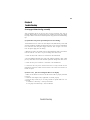
1
i
Preface
Copyright
This publication, including all photographs, illustrations and software, is protected
under international copyright laws, with all rights reserved. Neither this manual, nor
any of the material contained herein, may be reproduced without written consent of
the author.
Version 1.0
Disclaimer
The information in this document is subject to change without notice. The manufacturer makes no representations or warranties with respect to the contents hereof and
specifically disclaims any implied warranties of merchantability or fitness for any
particular purpose. The manufacturer reserves the right to revise this publication and
to make changes from time to time in the content hereof without obligation of the
manufacturer to notify any person of such revision or changes.
Trademark Recognition
Windows ® VISTA/7 are registered trademarks of Microsoft Corp.
Other product names used in this manual are the properties of their respective
owners and are acknowledged.
Federal Communications Commission (FCC)
This equipment has been tested and found to comply with the limits for a Class B
digital device, pursuant to Part 15 of the FCC Rules. These limits are designed to
provide reasonable protection against harmful interference in a residential installation. This equipment generates, uses, and can radiate radio frequency energy and, if
not installed and used in accordance with the instructions, may cause harmful interference to radio communications. However, there is no guarantee that interference
will not occur in a particular installation. If this equipment does cause harmful
interference to radio or television reception, which can be determined by turning the
equipment off and on, the user is encouraged to try to correct the interference by one
or more of the following measures:
•
•
•
•
Reorient or relocate the receiving antenna
Increase the separation between the equipment and the receiver
Connect the equipment onto an outlet on a circuit different from that to
which the receiver is connected
Consult the dealer or an experienced radio/TV technician for help
Shielded interconnect cables and a shielded AC power cable must be employed with
this equipment to ensure compliance with the pertinent RF emission limits governing this device. Changes or modifications not expressly approved by the system’s
manufacturer could void the user’s authority to operate the equipment.
Preface
ii
Declaration of Conformity
This device complies with part 15 of the FCC rules. Operation is subject to the
following conditions:
•
•
This device may not cause harmful interference, and
This device must accept any interference received, including interference that may cause undesired operation
Canadian Department of Communications
This class B digital apparatus meets all requirements of the Canadian Interferencecausing Equipment Regulations.
Cet appareil numérique de la classe B respecte toutes les exigences du Réglement sur
le matériel brouilieur du Canada.
Preface
iii
Safety Instructions
Your system is designed and tested to meet the latest standards of safety for information technology equipment. However, to ensure your safety, it is important that you
read the following safety instructions.
Setting up your system
•
•
•
•
•
•
Read and follow all instructions in the documentation before you operate your system.
Do not use this product near water or a heated source such as a
radiator.
Set up the system on a stable surface.
Openings on the chassis are for ventilation. Do not block or cover these
openings. Make sure you leave plenty of space around the system for
ventilation. Never insert objects of any kind into the ventilation openings.
Use this product in environments with ambient temperatures between
0°C and 40°C.
If you use an extension cord, make sure that the total ampere rating of
the devices plugged into the extension cord does not exceed its ampere rating.
Care during use
•
•
•
•
Do not walk on the power cord or allow anything to rest on it.
Do not spill water or any other liquids on your system.
When the system is turned OFF, a small amount of electrical currentstill
flows. Always unplug all power, modem, and network cables from the
power outlets before cleaning the system.
If you encounter the following technical problems with the product,
unplug the power cord and contact a qualified service technician or
your retailer.
•
•
•
•
•
The power cord or plug is damaged.
Liquid has been spilled into the system.
The system does not function properly even if you follow the
operating instructions.
The system was dropped or the cabinet is damaged.
The system performance changes
The warranty does not apply to products that have been disassembled by
users
Preface
iv
Safety cautions and warnings
Optical Drive Satety Information
Optical drive sold with this system contains a CLASS 1 LASER PRODUCT.
CAUTION:
Invisible laser radiation when open. Do not stare into beam or view
directly with optical instructions.
WARNING:
Makeing adjustments or performing procedures other than those specified in the user’s manual may result in hazardous laser exposuer. Do
not attempt to disassemble the optical drive. For your safety, have the
optical drive serviced only by an authorized service provider.
Product disposal notice
INPORTANT:
This symbol if the crossed out wheeled bin indicates that the product
(electrical and electronic equipment) should not be placed in municipal waste. Check local regulations for disposal of electronic products.
Nordic Lithium Cautions (for lithium-ion batteries)
CAUTION:
Danger of explosoin if battery is incorrectly replace only with the same
or equivalent type recommended by the manufacturer. Dispose of used
batteries according to the manufacturer’s instructions.
Product disposal notice
1. Do not place this product underneath heavy loads or in an unstable
position.
2. Do not use or expose this product around magnetic fields as magnetic interference may affect the performance of the product.
3. Do not expose this product to high levels of direct sunlight, highhumidity or wet conditions.
4. Do not block the air vents to this product or impede the airflow in
any way.
Preface
v
TABLE OF CONTENTS
Preface
i
Chapter 1
1
Introducing the PC
1
Introduction......................................................................................1
Specification......................................................................................2
Front and Rear I/O............................................................................3
Packing Contents..............................................................................5
Chapter 2
7
Installing the PC
7
System Quick Installing...................................................................7
Chapter 3
11
Using BIOS
11
About the Setup Utility................................................................ 11
The Standard Configuration..............................................11
Entering the Setup Utility...................................................11
Using BIOS......................................................................................12
Standard CMOS Setup......................................................13
Advanced Setup.................................................................15
Advanced Chipset Setup....................................................17
Integrated Peripherals.......................................................18
Power Management Setup.................................................19
PC Health Status................................................................20
Frequency/Voltage Control................................................21
Load Default Settings.........................................................23
Save & Exit Setup...............................................................23
Exit Without Saving............................................................23
vi
Chapter 4
25
Using the Software
25
About the Software DVD-ROM/CD-ROM.................................25
Auto-installing under Windows 7...............................................25
Running Setup....................................................................26
Manual Installation........................................................................28
Utility Software Reference............................................................28
1
Chapter 1
Introducing the PC
Introducting
Thank you for choosing 3.8L MS200 of great performance and with stylish and
flexible design.
Support Intel® Socket LGA1156 Core i3/i5 Clarkdale processors and a dimension of
270mm (H)* 205mm (D)* 70mm (W), 3.8L SFF provides the features of low power
consumption (working with a 120Watt power adaptor), low noise (<30db) and space
saving. The chipset is Intel® H55, supporting up to 8 GB of system memory with
DDR3 memory SO-DIMM, 3.5” SATA II HDD, Slim DVD Super-multi Tray type/
Tray-load Slim type ODD, and Build in Intel® HD Graphics.
Introducing the PC
2
Specification
Chipset
•
Intel® H55
CPU Support
•
Socket LGA1156 for Intel® Core i3/i5 Clarkdale
processors (up to 73W)
Memory
•
2 x SO-DIMM up to 8 GB
Graphics
Storage
•
•
Built-in Intel® HD graphics
Supported 1 x 3.5” SATA II HDD
ODD
•
Support Slim DVD Super-multi Tray type
Front Panel
•
•
•
•
4 x USB2.0
1 x Headphone output
1 x MIC-IN
1 x Multi-card reader slot
Rear Panel
•
•
•
•
•
•
4 x USB
1 x D-Sub, 1 x HDMI
1 x 10/100/1000 LAN RJ45
1 x TV Tuner (optional)
1 x Antenna (optional)
8 Channel Audio, 6 Jacks
Power
•
120W power adaptor
OS Support
•
Hardware Compatible with Windows 7
Expansion
•
1 x Mini PCIE
Dimensions (mm)
•
270mm * 205mm * 70mm
WARNING:
Please realize that there is a certain risk involved with overclocking, Including adjusting the setting in the BIOS, or using the third-party overclocking
tools. Overclocking may affect your system stability, or even case damage
to the components and devices of your system. It should be done at your
own risk and expense. We are not responsible for possible damage casesd
by overclocking.
Introducing the PC
3
Front and Rear I/O
1. Power Button
Press the prower button to turn the system on and
off.
2. 4 IN 1 Card
Reader
Supports SD Card/ MMC Card/ MS Card. You can easily read phone or other files on the momery card.
Your digital cameras, DVs, MP3 players or other digital devices are highly compatible.
3. USB Connectors
The USB connectors is for attaching USB devices,
such as mouse, keyboard, printer, scanner and other
USB-compatible device.
4. Mic In Jack
Connecting Microphone.
5. Headphone Jack
Connecting Headphone.
Introducing the PC
4
6. HDMI Connector
Connecting HDMI Device.
7. USB Connectors
Connecting USB Devices (USB2.0 Ports)
8. Eight channel HD
Audio
Microphone Jack/ Headphone Jack/ Line In Jack.
9. DC Jack
It is used for power adapter
10. Antenna
It is used for an optional antenna
11. D-SUB Connector
Connecting VGA Monitor.
12. LAN
Connecting the Network.
13. TV Tuner
(optional)
TV in jack.
Introducing the PC
5
Packing Contents
Driver DVD
Manual
Stand
Power
NOTE:
Please contact us immediately if any of the items is damaged or missing.
Introducing the PC
6
Memo
Introducing the PC
7
Chapter 2
Installing the PC
System Quick Installation
1. Connecting HDMI device.
2. Connecting VGA Monitor. (D-SUB Connector)
3. The USB connectors is for attaching USB devices, such as mouse, keyboard,
printer, scanner and other USB-compatible device.
Installing the PC
8
4. Connecting the Network. (LAN Connector)
5. Connecting the Microphone. (Microphone Jack)
6. Connecting Speakers or Headphones. (Headphone Jack)
7. Connecting External Audio Device. (Line In Jack)
Installing the PC
9
8. Connecting Power. (DC jack)
Installing the PC
10
Memo
Installing the PC
11
Chapter 3
Using BIOS
About the Setup Utility
The computer uses the latest “American Megatrends Inc. ” BIOS with support for
Windows Plug and Play. The CMOS chip on the motherboard contains the ROM
setup instructions for configuring the motherboard BIOS.
The BIOS (Basic Input and Output System) Setup Utility displays the system’s
configuration status and provides you with options to set system parameters. The
parameters are stored in battery-backed-up CMOS RAM that saves this information
when the power is turned off. When the system is turned back on, the system is
configured with the values you stored in CMOS.
The BIOS Setup Utility enables you to configure:
•
Hard drives, diskette drives and peripherals
•
Video display type and display options
•
Password protection from unauthorized use
•
Power Management features
The settings made in the Setup Utility affect how the computer performs. Before
using the Setup Utility, ensure that you understand the Setup Utility options.
This chapter provides explanations for Setup Utility options.
The Standard Configuration
A standard configuration has already been set in the Setup Utility. However, we
recommend that you read this chapter in case you need to make any changes in the
future.
This Setup Utility should be used:
•
when changing the system configuration
•
when a configuration error is detected and you are prompted to make
changes to the Setup Utility
•
when trying to resolve IRQ conflicts
•
when making changes to the Power Management configuration
•
when changing the password or making other changes to the Security
Setup
Entering the Setup Utility
When you power on the system, BIOS enters the Power-On Self Test (POST)
routines. POST is a series of built-in diagnostics performed by the BIOS. After the
POST routines are completed, the following message appears:
Press DEL to enter SETUP
Using BIOS
12
Press the delete key to access the BIOS Setup Utility.
CMOS Setup Utility - Copyright (C) 1985-2010, American Megatrends, Inc.
fFrequency/Voltage Control
fBIOS Security Features
fStandard CMOS Setup
fAdvanced BIOS Features
fAdvanced Chipset Features
fIntegrated Peripherals
fPower Management Setup
f PC Health Status
Load Default Setting
Save & Exit Setup
Exit Without Saving
mnlk : Move
Enter : Select +/-/: Value F10: Save ESC: Exit F1:General Help
F7: Previous Values
F9: Optimized Defaults
F8: Fail-Safe Defaults
Configure Time and Date. Display System Information...
v02.67 (C)Copyright 1985-2010, American Megatrends, Inc.
Using BIOS
When you start the Setup Utility, the main menu appears. The main menu of the
Setup Utility displays a list of the options that are available. A highlight indicates
which option is currently selected. Use the cursor arrow keys to move the highlight
to other options. When an option is highlighted, execute the option by pressing
<Enter>.
Some options lead to pop-up dialog boxes that prompt you to verify that you wish to
execute that option. Other options lead to dialog boxes that prompt you for information.
Some options (marked with a triangle f) lead to submenus that enable you to change
the values for the option. Use the cursor arrow keys to scroll through the items in the
submenu.
In this manual, default values are enclosed in parenthesis. Submenu items are denoted
by a triangle f .
The default BIOS setting for this motherboard apply for most conditions
with optimum performance. We do not suggest users change the default
values in the BIOS setup and take no responsibility to any damage caused
by changing the BIOS settings.
BIOS Navigation Keys
The BIOS navigation keys are listed below:
KEY
ESC
mnlk
+/Enter
FUNCTION
Exits the current menu
Scrolls through the items on a menu
Modifies the selected field’s values
Select
F9
Loads an optimized setting for better performance
F10
Saves the current configuration and exits setup
F1
Displays a screen that describes all key functions
Using BIOS
13
For the purpose of better product maintenance, we reserve the right to
change the BIOS items presented in the manual. The BIOS setup screens
shown in this chapter are for reference only. Please visit our website for
updated manual.
Standard CMOS Setup
This option displays basic information about your system.
CMOS Setup Utility - Copyright (C) 1985-2010, American Megatrends, Inc.
Standard CMOS Setup
System Date
System Time
Thu 0101/2009
12 :09 :26
f SATA Port1
f SATA Port2
ATAPI CDROM
Hard Disk
Help Item
Use [ENTER], [TAB]
or [SHIFT-TAB] to
select a field.
Use [+] or [-] to
configure system Date.
mnlk : Move
Enter : Select +/-/: Value F10: Save ESC: Exit F1:General Help
F7: Previous Values
F9: Optimized Defaults
F8: Fail-Safe Defaults
System Date & System Time
The Date and Time items show the current date and time on the computer. If you are
running a Windows OS, these items are automatically updated whenever you make
changes to the Windows Date and Time Properties utility.
fSATA Port 1~2
This motherboard supports two SATA channels and each channel allows one SATA
device to be installed.
CMOS Setup Utility - Copyright (C) 1985-2010, American Megatrends, Inc.
SATA Port1
Help Item
SATA Port1
Device
Vendor
LBA Mode
PIO Mode
Async DMA
Ultra DMA
Type
PIO Mode
DMA Mode
: ATAPI CDROM
: Optiarc DVD RW AD-7643S
: Supported
:4
: MultiWord DMA-2
:Ultra DMA-5
Select the type
of the device connected
to the system.
Auto
Auto
Auto
mnlk : Move
Enter : Select +/-/: Value F10: Save ESC: Exit F1:General Help
F7: Previous Values
F9: Optimzed Defaults
F8: Fail-Safe Defaults
Using BIOS
14
Type (Auto)
Use this item to configure the type of the IDE device that you specify. If the feature
is enabled, it will enhance hard disk performance by reading or writing more data
during each transfer.
PIO Mode (Auto)
Use this item to set the PIO mode to enhance hard disk performance by optimizing
the hard disk timing.
DMA Mode (Auto)
DMA capability allows users to improve the transfer-speed and data-integrity for
compatible IDE devices.
Press <Esc> to return to the Standard CMOS Setup page.
Using BIOS
15
Advanced Setup
This page sets up more advanced information about your system. Handle this page
with caution. Any changes can affect the operation of your computer.
CMOS Setup Utility - Copyright (C) 1985-2010, American Megatrends, Inc.
Advanced BIOS Features
Quick Boot
Quiet Boot
1st Boot Device
2nd Boot Device
3rd Boot Device
4th Boot Device
f Hard Disk Driver Priority
f Optical Disk Driver Priority
Bootup Num-Lock
Boot Sector Virus Protection
USB Beep Message
Enabled
Enabled
Hard Disk Drive
CD/DVD
Removable Device
LAN
Press Enter
Press Enter
On
Disabled
Disabled
Help Item
Allows BIOS to skip
certain tests while booting. This will decrease
the time needed to boot
the system.
mnlk : Move
Enter : Select +/-/: Value F10: Save ESC: Exit F1:General Help
F7: Previous Values
F9: Optimized Defaults
F8: Fail-Safe Defaults
Quick Boot (Enabled)
If you enable this item, the system starts up more quickly be elimination some of
thepower on test routines.
Quiet Boot (Enabled)
If enabled, BIOS will show a full screen logo at boot; if disabled, BIOS will set the
initialdisplay mode to BIOS and show the diagnostic POST screen at boot.
1st/2nd/3rd/4th Boot Device (Hard Drive/CD/DVD/Removable Dev./LAN)
Use this item to determine the device order the computer used to look for an
operating system to load at start-up time. The devices showed here will be different
depending on the exact devices installed on your motherboard.
fHard Disk Drive Priority (Press Enter)
Scroll to this item and press <Enter> to view the following screen:
CMOS Setup Utility - Copyright (C) 1985-2010, American Megatrends, Inc.
Hard Disk Driver Priority
Help Item
Hard Disk Driver
1st Drive
SATA: SM-ST3250620AS
mnlk : Move
Enter : Select
F1: General Help
Specifies the boot
sequence from the
available devices.
+/-/: Value F10: Save ESC: Exit
F9: Optimized Defaults
Press <Esc> to return to the Advanced BIOS Features page.
Using BIOS
16
fOptical Disk Driver Priority (Press Enter)
Scroll to this item and press <Enter> to view the following screen:
CMOS Setup Utility - Copyright (C) 1985-2010, American Megatrends, Inc.
Optical Disk Driver Priority
Help Item
Optical Disk Driver
1st Drive
CD/DVD: PM-Optiarc D
mnlk : Move
Enter : Select
F1: General Help
Specifies the boot
sequence from the
available devices.
+/-/: Value F10: Save ESC: Exit
F9: Optimized Defaults
Press <Esc> to return to the Advanced BIOS Features page.
Boot Up Num-Lock (On)
This item defines if the keyboard Num Lock key is active when your system is
started.
Boot Sector Virus Protection (Disabled)
If set to Disabled, when anything attempts to access the boot sector or hard disk
partitiontable, there will be no warning message to appear.
USB Beep Message (Disabled)
This item disables/enables the beep during USB device enumeration.
Press <Esc> to return to the main menu setting page.
Using BIOS
17
Advanced Chipset Setup
This page sets up more advanced information about your system. Handle this page
with caution. Any changes can affect the operation of your computer.
CMOS Setup Utility - Copyright (C) 1985-2010, American Megatrends, Inc.
Advanced Chipset Setup
Intel EIST
Intel XD Bit
Intel VT
Memory Hole Remapping
Video Memory Size
DVMT Mode
DVMT/Fixed Memory Size
Enabled
Enabled
Enabled
Enabled
32MB
DVMT Mode
256MB
Help Item
When disabled, force
the XD feature flag to
always return to 0.
mnlk : Move
Enter : Select +/-/: Value F10: Save ESC: Exit F1:General Help
F7: Previous Values
F9: Optimized Defaults
F8: Fail-Safe Defaults
Intel EIST (Enabled)
This item allows users to enable or disable the EIST (Enhanced Intel SpeedStep
technology).
Intel XD Bit (Enabled)
This item allows users to enable or disable the Intel XD bit.
Intel VT (Enabled)
This item allows you to enable or disable the Intel. virtualization Technology (Intel.
VT)function.
Memory Hole Remapping (Enabled)
This item allows users to enable or disable memory hole remapping.
Video Memory Size (32MB)
This item applies to chipsets/motherboards capable of the HyperMemory Support.
DVMT Mode (DVMT Mode)
DVMT is Dynamic Video Memory Technology. This item helps you select video
mode.
DVMT/Fixed Memory Size (256MB)
When set to Fixed Mode, the graphics driver will reserve a fixed portion of the
systemmemory as graphics memory. When set to DVMT Mode, the graphics chip
will dynamicallyallocate system memory as graphics memory, according to system
and graphics require-ments.
Press <Esc> to return to the main menu setting page.
Using BIOS
18
Integrated Peripherals
This page sets up some parameters for peripheral devices connected to the system.
CMOS Setup Utility - Copyright (C) 1985-2010, American Megatrends, Inc.
Integrated Peripherals
Onboard SATA Controller
Onboard SATA Mode
Onboard USB Controller
Legacy USB Support
Onboard Audio Controller
Onboard LAN Controller
Onboard LAN Option ROM
Enabled
Native IDE
Enabled
Enabled
Enabled
Enabled
Disabled
Help Item
Options
Disabled
Enabled
mnlk : Move
Enter : Select +/-/: Value F10: Save ESC: Exit F1:General Help
F7: Previous Values
F9: Optimized Defaults
F8: Fail-Safe Defaults
Onboard SATA Controller (Enabled)
This item allows you to enable or disable the onboard SATA controller.
Onboard SATA Mode (Native IDE)
Use this item to select the mode of the Serial ATA.
Onboard USB Controller (Enabled)
Enables or disables the onboard USB controller. We recommend users keep the
default value. Disabling it might cause the USB devices not to work properly.
Legacy USB Support (Enabled)
Use this item to enable or disable support for legacy USB devices.
Onboard LAN Controller (Enabled)
This option allows you to control the onboard LAN device.
Onboard LAN Option ROM (Disabled)
This item enables or disables the onboard LAN option ROM function.
Press <Esc> to return to the main menu setting page.
Using BIOS
19
Power Management Setup
This page sets up some parameters for system power management operation.
CMOS Setup Utility - Copyright (C) 1985-2010, American Megatrends, Inc.
Power Management Setup
ACPI Aware O/S
Suspend mode
Deep Power Off Mode
Power On by RTC Alarm
Power On by PCIE Devices
Wake Up by USB KB/Mouse
Restore On AC Power Loss
Yes
S3 (STR)
Enabled
Disabled
Disabled
Enabled
Last State
Help Item
Enable/Disable
ACPI support for
Operating System.
Enable: If OS
Supports ACPI
Disable: If OS
does not support
ACPI.
mnlk : Move
Enter : Select +/-/: Value F10: Save ESC: Exit F1:General Help
F7: Previous Values
F9: Optimized Defaults
F8: Fail-Safe Defaults
ACPI Aware O/S (Yes)
This item supports ACPI (Advanced Configuration and Power management Interface). Use this item to enable or disable the ACPI feature.
Suspend Mode (S3 (STR))
Use this item to define how your system suspends. In the default, S3 (STR), the
suspendmode is suspend to RAM, i.e., the system shuts down with the exception of a
refresh currentto the system memory.
Deep Power Off Mode (Disabled)
This item allows you to enable/disable the USB device wakeup function from S3/S4
mode.
Power On by RTC Alarm (Disabled)
The system can be turned off with a software command. If you enable this item, the
systemcan automatically resume at a fixed time based on the system¡¯ RTC (realtime
clock). Usethe items below this one to set the date and time of the wake-up alarm.
You must use an ATXpower supply in order to use this feature.
Power On by PCIE Devices (Disabled)
The system can be turned off with a software command. If you enable this item, the
systemcan automatically resume if there is an incoming call on the PCIE LAN card.
You must usean ATX power supply in order to use this feature. Use this item to do
wake-up action ifinserting the PCIE card.
Wake Up by USB KB/Mouse (Enabled)
This item enables or disables you to allow keyboard or mouse activity to awaken the
systemfrom power saving mode.
Restore On AC Power Loss (Last State)
This item defines how the system will act after AC power loss during system
operation.When you set to Off, it will keep the system in Off state until the power
button is pressed.
Press <Esc> to return to the main menu setting page.
Using BIOS
20
PC Health Status
On motherboards support hardware monitoring, this item lets you monitor the
parameters for critical voltages, temperatures and fan speeds.
CMOS Setup Utility - Copyright (C) 1985-2010, American Megatrends, Inc.
PC Health Status
Help Item
CPU Temperature (PECI Mode) :
System Temperature
:
CPU Fan1 Speed
:
CPU Fan2 Speed
:
CPU Core
:
+ 3.30V
:
+ 5.00 V
:
+12.0 V
:
5VSB
:
VBAT
:
43
42°C/107°F
1066 RPM
1146 RPM
1.120 V
3.296 V
5.053 V
12.032 V
5.026 V
3.216 V
System Shutdown Temperature
Smart Fan
Disabled
Enabled
mnlk : Move
Options
Disabled
Enabled
Enter : Select +/-/: Value F10: Save ESC: Exit F1:General Help
F7: Previous Values
F9: Optimized Defaults
F8: Fail-Safe Defaults
Using BIOS
21
System Component Characteristics
These items display the monitoring of the overall inboard hardware health events,
such as System & CPU temperature, CPU & DIMM voltage, CPU & system fan
speed,...etc.
•
•
•
•
•
•
•
•
•
•
CPU Temperature (PECI Mode)
System Temperature
CPU Fan1 Speed
CPU Fan2 Speed
CPU Core
+ 3.30V
+ 5.00V
+ 12.00V
5VSB
VBAT
Shutdown Temperature (Disabled)
Enable you to set the maximum temperature the system can reach before powering
down.
Smart Fan (Enabled)
If enable, fan speed will speed-up or slow-down according the temperature.
Press <Esc> to return to the main menu setting page.
Frequency/Voltage Control
This page enables you to set the clock speed and system bus for your system. The
clock speed and system bus are determined by the kind of processor you have installed in your system.
CMOS Setup Utility - Copyright (C) 1985-2010, American Megatrends, Inc.
Frequency/Voltage Control
Enable Clock to All PCI/PCIE
Disabled
Spread Spectrum
Enabled
Ratio Status: Unlocked (Min: 09, Max: 23)
Ratio CMOS Setting
23
mnlk : Move
Help Item
Options
Disabled
Enabled
Enter : Select +/-/: Value F10: Save ESC: Exit F1:General Help
F7: Previous Values
F9: Optimized Defaults
F8: Fail-Safe Defaults
Using BIOS
22
Enable Clock to All PCI/PCIE (Disabled)
This item displays the information of current manufacturer of the CPU installed in
your computer.
Ratio Actual Value: 12
This item shows the actual ratio of the CPU installed in your system.
CPU Frequency Setting (533MHz)
This item is used to set the CPU Frequency.
CPU Spread Spectrum (Disabled)
If you enable spread spectrum, it can significantly reduce the EMI (Electro-Magnetic Interference) generated by the system.
Press <Esc> to return to the main menu setting page.
BIOS Security Features
This page enables you to set the clock speed and system bus for your system. The
clock speed and system bus are determined by the kind of processor you have installed in your system.
CMOS Setup Utility - Copyright (C) 1985-2010, American Megatrends, Inc.
BIOS Security Features
Supervisor Password
User Password
Help Item
: Installed
: Installed
Change Supervisor Password
Change User Password
Security Check
Press Enter
Press Enter
Setup
Install or change the
password
mnlk : Move
Enter : Select +/-/: Value F10: Save ESC: Exit F1:General Help
F7: Previous Values
F9: Optimized Defaults
F8: Fail-Safe Defaults
Supervisor Password (Installed)
This item indicates whether a supervisor password has been set. If the password has
beeninstalled, Installed displays. If not, Not Installed displays.
User Password (Installed)
This item indicates whether a user password has been set. If the password has been
installed,Installed displays. If not, Not Installed displays.
Change Supervisor Password (Press Enter)
You can select this option and press <Enter> to access the sub menu. You can use the
submenu to change the supervisor password.
Using BIOS
23
Change User Password (Press Enter)
You can select this option and press <Enter> to access the sub menu. You can use the
submenu to change the user password.
Security Check (Setup)
This item is set to enable or disable the security check.
Load Default Settings
This option opens a dialog box that lets you install stability-oriented defaults for
all appropriate items in the Setup Utility. Select <OK> and then press <Enter> to
install the defaults. Select <Cancel> and then press <Enter> to not install the
defaults.
Save & Exit Setup
Highlight this item and press <Enter> to save the changes that you have made in the
Setup Utility and exit the Setup Utility. When the Save and Exit dialog box appears,
select [OK] to save and exit, or select [Cancel] to return to the main menu.
Exit Without Saving
Highlight this item and press <Enter> to discard any changes that you have made in
the Setup Utility and exit the Setup Utility. When the Exit Without Saving dialog
box appears, select [OK] to discard changes and exit, or select [Cancel] to return to
the main menu.
If you have made settings that you do not want to save, use the “Exit
Without Saving” item and select [OK] to discard any changes you have
made.
Using BIOS
24
Memo
Using BIOS
25
Chapter 4
Using the Software
About the Software DVD-ROM/CD-ROM
The support software DVD-ROM/CD-ROM that is included in the motherboard
package contains all the drivers and utility programs needed to properly run the
bundled products. Below you can find a brief description of each software program,
and the location for your motherboard version. More information on some programs is available in a README file, located in the same directory as the software.
Before installing any software, always inspect the folder for files named README.TXT
or something similar. These files may contain important information that is not
included in this manual.
1. Never try to install all software from folder that is not specified for use with
your motherboard.
2. The notice of Intel HD audio installation (optional): The Intel High Definition audio functionality unexpectedly quits working in Windows Server
2003 Service Pack 1 or Windows XP Professional x64 Edition. Users need
to download and install the update packages from the Microsoft Download
Center “before” installing HD audio driver bundled in the Driver disk.
Please log on to http://support.microsoft.com/default.aspx?scid=kb;enus;901105#appliesto for more information.
Auto-installing under Windows 7
The Auto-install DVD-ROM/CD-ROM makes it easy for you to install the drivers
and software for your motherboard.
If the Auto-install DVD-ROM/CD-ROM does not work on your system,
you can still install drivers through the file manager for your OS (for
example, Windows Explorer). Refer to the Utility Folder Installation Notes
later in this chapter.
The support software DVD-ROM/CD-ROM disk loads automatically under Windows
7. When you insert the DVD-ROM/CD-ROM disk in the DVD-ROM/CD-ROM drive,
the autorun feature will automatically bring up the install screen. The screen has
three buttons on it, Setup, Browse CD and Exit.
If the opening screen does not appear; double-click the file “setup.exe”
in the root directory.
Using the Software
26
Drivers Tab
Setup
Click the Setup button to run the software installation program.
Select from the menu which software you want to install.
Browse CD The Browse CD button is the standard Windows command that allows you to open Windows Explorer and show the contents of the
support disk.
Before installing the software from Windows Explorer, look for a file
named README.TXT or something similar. This file may contain
important information to help you install the software correctly.
Some software is installed in separate folders for different operating
systems, such as Windows 7. Always go to the correct folder for the
kind of OS you are using.
In install the software, execute a file named SETUP.EXE by doubleclicking the file and then following the instructions on the screen.
Exit
The Exit button closes the Auto Setup window.
Utilities Tab
Lists the software utilities that are available on the disk.
Information Tab
Displays the path for all software and drivers available on the disk.
Running Setup
Follow these instructions to install device drivers and software for the motherboard:
1.
Click Setup. The installation program begins:
The following screens are examples only. The screens and driver lists will be
different according to the motherboard you are installing.
The motherboard identification is located in the upper left-hand corner.
Using the Software
27
2.
Click Next. The following screen appears:
3.
Check the box next to the items you want to install. The default options are recommended.
4.
Click Next run the Installation Wizard. An item installation screen appears:
5.
Follow the instructions on the screen to install the items.
Drivers and software are automatically installed in sequence. Follow the
onscreen instructions, confirm commands and allow the computer to
restart a few times to complete the installation.
Using the Software
28
Windows 7 will appear below UAC (User Account Control) message after the
system restart. You must select “Allow” to install the next driver. Continue
this process to complete the drivers installation.
Manual Installation
Insert the disk in the DVD-ROM/CD-ROM drive and locate the PATH.DOC file in
the root directory. This file contains the information needed to locate the drivers for
your motherboard.
Look for the chipset and motherboard model; then browse to the directory and path
to begin installing the drivers. Most drivers have a setup program (SETUP.EXE) that
automatically detects your operating system before installation. Other drivers have
the setup program located in the operating system subfolder.
If the driver you want to install does not have a setup program, browse to the
operating system subfolder and locate the readme text file (README.TXT or
README.DOC) for information on installing the driver or software for your operating system.
Utility Software Reference
All the utility software available from this page is Windows compliant. They are
provided only for the convenience of the customer. The following software is furnished under license and may only be used or copied in accordance with the terms of
the license.
These software(s) are subject to change at anytime without prior notice.
Please refer to the support disk for available software.
Using the Software
29
Chapter 5
Trouble Shooting
Start up problems during assembly
After assembling the PC for the first time you may experience some start up
problems. Before calling for technical support or returning for warranty, this chapter
may help to address some of the common questions using some basic troubleshooting
tips.
a) System does not power up and the fans are not running.
1.Disassemble the PC to remove the VGA adaptor card, DDR memory, LAN, USB
and other peripherals including keyboard and mouse. Leave only the motherboard,
CPU with CPU cooler and power supply connected. Turn on again to see if the
CPU and power supply fans are running.
2. Make sure to remove any unused screws or other metal objects such as screwdrivers
from the inside PC case. This is to prevent damage from short circuit.
3. Check the CPU FAN connector is connected to the motherboard.
4. For Intel platforms check the pins on the CPU socket for damage or bent. A bent
pin may cause failure to boot and sometimes permanent damage from short circuit.
5. Check the 12V power connector is connected to the motherboard.
6. Check that the 12V power & ATX connectors are fully inserted into the
motherboard connectors. Make sure the latches of the cable and connector are
locked into place.
b) Power is on, fans are running but there is no display
1. Make sure the monitor is turned on and the monitor cable is properly connected
to the PC.
2. Check the VGA adapter card (if applicable) is inserted properly.
3. Listen for beep sounds. If you are using internal PC speaker make sure it is
connected.
a. continuous 3 short beeps : memory not detected
b. 1 long beep and 8 short beeps : VGA not detected
Trouble Shooting
30
c) The PC suddenly shuts down while booting up.
1. The CPU may experience overheating so it will shutdown to protect itself.
Ensure the CPU fan is working properly.
2. From the BIOS setting, try to disable the Smartfan function to let the fan run at
default speed. Doing a Load Optimised Default will also disable the Smartfan.
Start up problems after prolong use
After a prolong period of use your PC may experience start up problems again.
This may be caused by breakdown of devices connected to the motherboard such as
HDD, CPU fan, etc. The following tips may help to revive the PC or identify the
cause of failure.
1. Clear the CMOS values using the CLR_CMOS jumper. Refer to CLR_CMOS
jumper in Chapter 2 for Checking Jumper Settings in this user manual. When
completed, follow up with a Load Optimised Default in the BIOS setup.
2. Check the system fan for dust. Long term accumulation of dust will reduce its
effectiveness to cool the processor. Clean the cooler or replace a new one if
necessary.
3. Remove the hard drive, optical drive or DDR memory to determine which of
these component may be at fault.
Maintenance and care tips
Your computer, like any electrical appliance, requires proper care and maintenance.
Here are some basic PC care tips to help prolong the life of the motherboard and
keep it running as best as it can.
1. Keep your computer in a well ventilated area. Leave some space between
the PC and the wall for sufficient airflow.
2. Keep your computer in a cool dry place. Avoid dusty areas, direct sunlight
and areas of high moisture content.
3. Routinely clean the CPU cooler fan to remove dust and hair.
4. In places of hot and humid weather you should turn on your computer once
every other week to circulate the air and prevent damage from humidity.
5. Add more memory to your computer if possible. This not only speeds up the
system but also reduces the loading of your hard drive to prolong its life span.
6. If possible, ensure the power cord has an earth ground pin directly from the
wall outlet. This will reduce voltage fluctuation that may damage sensitive devices.
Trouble Shooting
If fail, contact RMA
CLR CMOS and restart.
Yes
Halt at POST screen?
Yes
Check if monitor has
display
Yes
Check if Power Supply
Unit (PSU) is working
Power Bu on is pressed
but PC fails to start.
CMOS setup error,
-
need to CLRCMOS.
HDD problem.
-
Peripheral device issue
No
No
No
VGA not detected
- If 1 long beep and 8 short beeps:
inserted or memory failure
DIMM memory not properly
- If 3 short beeps:
Yes
Any Beep sound?
No
Yes
Check if monitor
has display
Restart the PC
is connected
if CPU 12V power
CLR CMOS and check
Basic Troubleshooting Flowchart
Board problem
-> contact RMA
a er modify BIOS se ng.
System fail to start or unstable
No
If board problem -> contact RMA
Problem with PSU or board?
Yes
and PSU switch is turned on?
AC power cord is plugged
CLR CMOS and restart
and restart.
or connect to wall socket
Turn on PSU switch
No
31
32
Memo
Trouble Shooting