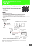
1
Machine Automation Controller NX-series Communications Interface Units User’s Manual NX-CIF Communications Interface Units W540-E1-01 NOTE All rights reserved. No part of this publication may be reproduced, stored in a retrieval system, or transmitted, in any form, or by any means, mechanical, electronic, photocopying, recording, or otherwise, without the prior written permission of OMRON. No patent liability is assumed with respect to the use of the information contained herein. Moreover, because OMRON is constantly striving to improve its high-quality products, the information contained in this manual is subject to change without notice. Every precaution has been taken in the preparation of this manual. Nevertheless, OMRON assumes no responsibility for errors or omissions. Neither is any liability assumed for damages resulting from the use of the information contained in this publication. Trademarks • Sysmac and SYSMAC are trademarks or registered trademarks of OMRON Corporation in Japan and other countries for OMRON factory automation products. • Microsoft, Windows, Windows Vista, Excel, and Visual Basic are either registered trademarks or trademarks of Microsoft Corporation in the United States and other countries. • EtherCAT® is registered trademark and patented technology, licensed by Beckhoff Automation GmbH, Germany. • Safety over EtherCAT® is registered trademark and patented technology, licensed by Beckhoff Automation GmbH, Germany. • ODVA, CIP, CompoNet, DeviceNet, and EtherNet/IP are trademarks of ODVA. • The SD and SDHC logos are trademarks of SD-3C, LLC. Other company names and product names in this document are the trademarks or registered trademarks of their respective companies. Copyrights Microsoft product screen shots reprinted with permission from Microsoft Corporation. Introduction Introduction Thank you for purchasing an NX-series Communications Interface Unit. This manual contains information that is necessary to use the NX-series Communications Interface Units. Please read this manual and make sure you understand the functionality and performance of the NX-series Communications Interface Unit before you attempt to use it in a control system. Keep this manual in a safe place where it will be available for reference during operation. Intended Audience This manual is intended for the following personnel, who must also have knowledge of electrical systems (an electrical engineer or the equivalent). • Personnel in charge of introducing FA systems. • Personnel in charge of designing FA systems. • Personnel in charge of installing and maintaining FA systems. • Personnel in charge of managing FA systems and facilities. For programming, this manual is intended for personnel who understand the programming language specifications in international standard IEC 61131-3 or Japanese standard JIS B 3503. Applicable Products This manual covers the following products. • NX-series Communications Interface Units NX-CIF Part of the specifications and restrictions for the CPU Units are given in other manuals. Refer to Relevant Manuals on page 6 and Related Manuals on page 26. NX-series Communications Interface Units User’s Manual (W540) 1 CONTENTS CONTENTS Introduction .............................................................................................................. 1 Intended Audience....................................................................................................................................... 1 Applicable Products ..................................................................................................................................... 1 Relevant Manuals ..................................................................................................... 6 Manual Structure ...................................................................................................... 7 Page Structure and Icons ............................................................................................................................ 7 Special Information ...................................................................................................................................... 8 Precautions on Terminology ........................................................................................................................ 8 Terms and Conditions Agreement .......................................................................... 9 Warranty, Limitations of Liability .................................................................................................................. 9 Application Considerations ........................................................................................................................ 10 Disclaimers ................................................................................................................................................ 10 Safety Precautions ................................................................................................. 11 Precautions for Safe Use ....................................................................................... 15 Precautions for Correct Use.................................................................................. 19 Regulations and Standards ................................................................................... 21 Conformance to EC Directives .................................................................................................................. 21 Conformance to UL and CSA Standards ................................................................................................... 22 Conformance to Shipbuilding Standards ................................................................................................... 22 Conformance to KC Standards .................................................................................................................. 22 Software Licenses and Copyrights ............................................................................................................ 22 Unit Versions .......................................................................................................... 23 Unit Versions.............................................................................................................................................. 23 Unit Versions and Sysmac Studio Versions ............................................................................................... 25 Related Manuals ..................................................................................................... 26 Revision History ..................................................................................................... 29 Sections in this Manual ......................................................................................... 31 Section 1 Features and System Configuration 1-1 Features of Communications Interface Units ..................................................................... 1-2 1-2 System Configuration ........................................................................................................... 1-3 1-3 Unit Models, Functions, and Support Software.................................................................. 1-5 1-3-1 1-3-2 1-3-3 2 Unit Model Numbers ................................................................................................................... 1-5 Functions..................................................................................................................................... 1-5 Support Software ........................................................................................................................ 1-5 NX-series Communications Interface Units User’s Manual (W540) CONTENTS Section 2 2-1 Specifications and Application Procedures Specifications ........................................................................................................................ 2-2 2-1-1 2-1-2 2-2 Application Procedures ........................................................................................................ 2-5 Section 3 3-1 Part Names and Functions Part Names............................................................................................................................. 3-2 3-1-1 3-1-2 3-2 General Specifications ................................................................................................................ 2-2 Specifications of Individual Units................................................................................................. 2-3 NX-CIF101 and NX-CIF105 ........................................................................................................ 3-2 NX-CIF210 .................................................................................................................................. 3-4 Indicators ............................................................................................................................... 3-5 3-2-1 3-2-2 Section 4 TS Indicator................................................................................................................................. 3-5 Send/Receive Indicators ............................................................................................................. 3-6 Installation and Wiring 4-1 Installing NX Units ................................................................................................................. 4-2 4-2 Wiring the Power Supply and Ground to the Slave Terminal ............................................ 4-3 4-3 Wiring the Terminals ............................................................................................................. 4-4 4-3-1 4-3-2 4-4 Wiring the Screwless Clamping Terminal Blocks ........................................................................ 4-4 Wiring the D-Sub Connector ....................................................................................................... 4-5 Wiring Communications ....................................................................................................... 4-6 4-4-1 4-4-2 4-4-3 Section 5 Terminal Arrangement................................................................................................................. 4-6 Connecting to Serial Communications Devices .......................................................................... 4-9 Examples of Recommended RS-232C and RS-422A/485 Wiring ............................................ 4-13 I/O Data Specifications 5-1 I/O Data Specifications for NX-CIF101 and NX-CIF105....................................................... 5-2 5-2 I/O Data Specifications for NX-CIF210 ................................................................................. 5-3 Section 6 6-1 Unit Settings Unit Operation Settings ........................................................................................................ 6-2 6-1-1 6-1-2 6-1-3 Communications Specifications .................................................................................................. 6-2 Transmission Buffering................................................................................................................ 6-2 Event Levels................................................................................................................................ 6-4 6-2 Unit Operation Setting Procedure........................................................................................ 6-5 6-3 Setting the PDO Sizes ........................................................................................................... 6-6 Section 7 Serial Communications 7-1 No-protocol Communications .............................................................................................. 7-3 7-2 How Data Is Sent and Received ........................................................................................... 7-4 7-2-1 7-2-2 How Data Is Sent ........................................................................................................................ 7-4 How Data Is Received................................................................................................................. 7-5 NX-series Communications Interface Units User’s Manual (W540) 3 CONTENTS 7-3 Data Used in PDO Communications .................................................................................... 7-6 7-3-1 7-3-2 7-3-3 7-3-4 7-4 PDO Communications Examples ....................................................................................... 7-12 7-4-1 7-4-2 7-4-3 7-4-4 7-4-5 7-5 7-6-4 Section 8 How the Serial Line Monitor Works ..................................................................................... 8-2 Monitor Data Contents ................................................................................................................ 8-2 CIF Serial Line Monitor Tab Page ............................................................................................... 8-3 Processing When a Buffer Becomes Full.................................................................................... 8-4 Importing and Exporting Monitor Data ........................................................................................ 8-4 Searching for Text Strings in Monitor Data.................................................................................. 8-4 Creating CSV Files of Monitor Data ............................................................................................ 8-5 Processing for Multiple Units and Ports ...................................................................................... 8-5 Operation with the Sysmac Studio ...................................................................................... 8-6 8-2-1 8-2-2 Section 9 Displaying the CIF Serial Line Monitor Tab Page........................................................................ 8-6 Starting and Stopping Monitoring and Displaying Monitor Data .................................................. 8-8 Troubleshooting 9-1 How to Check for Errors ....................................................................................................... 9-2 9-2 Checking for Errors with the Indicators .............................................................................. 9-3 9-3 Checking for Errors and Troubleshooting on the Sysmac Studio.................................... 9-4 9-3-1 9-3-2 4 Calculating the Communications Performance ......................................................................... 7-30 Adjusting PDO Sizes to Improve Communications Performance ............................................. 7-34 Processing When the Send Buffer or Receive Buffer Becomes Full ........................................ 7-36 Serial Line Monitor 8-1-1 8-1-2 8-1-3 8-1-4 8-1-5 8-1-6 8-1-7 8-2 Mismatched Values for the Input SID and Output SID .............................................................. 7-29 User Program Processing ......................................................................................................... 7-29 Communications Performance .......................................................................................... 7-30 7-8-1 7-8-2 7-8-3 8-1 Checking Input Notification Data............................................................................................... 7-27 Creating and Outputting Output Notification Data..................................................................... 7-27 Determining Conditions to Start Reception and Conditions for the Completion of the Reception.......................................................................................... 7-27 Precautions for Writing User Programming to Receive Data .................................................... 7-27 User Programming to Restart a Port ................................................................................. 7-29 7-7-1 7-7-2 7-8 Creating and Outputting Output Notification Data..................................................................... 7-26 Checking Input Notification Data............................................................................................... 7-26 Processing Send Data .............................................................................................................. 7-26 User Programming to Receive Data................................................................................... 7-27 7-6-1 7-6-2 7-6-3 7-7 Example of Sending Data ......................................................................................................... 7-12 Example of Receiving Data....................................................................................................... 7-15 Simultaneously Sending and Receiving Data ........................................................................... 7-18 Example for a Parity Error during Data Reception .................................................................... 7-20 Example of Control Command Execution ................................................................................. 7-22 User Programming to Send Data ....................................................................................... 7-26 7-5-1 7-5-2 7-5-3 7-6 Input Notification Data and Output Notification Data................................................................... 7-6 SIDs and SID Responses ........................................................................................................... 7-6 Input Data Type and Output Data Type....................................................................................... 7-9 Send Completed Toggle Bit......................................................................................................... 7-9 Checking for Errors from the Sysmac Studio .............................................................................. 9-4 Event Codes for Errors and Troubleshooting Procedures .......................................................... 9-5 9-4 Resetting Errors .................................................................................................................. 9-18 9-5 Troubleshooting Flow ......................................................................................................... 9-19 NX-series Communications Interface Units User’s Manual (W540) CONTENTS Section 10 Maintenance and Inspections 10-1 Cleaning and Inspections ................................................................................................... 10-2 10-1-1 Cleaning .................................................................................................................................... 10-2 10-1-2 Periodic Inspection.................................................................................................................... 10-2 10-2 Maintenance Procedures .................................................................................................... 10-5 Appendices A-1 Dimensions ............................................................................................................................A-2 A-1-1 A-1-2 NX-CIF101 and NX-CIF105 ........................................................................................................A-2 NX-CIF210 ..................................................................................................................................A-2 A-2 Changing NX Objects from a User Program .......................................................................A-4 A-2-1 A-2-2 NX Objects That You Can Change .............................................................................................A-4 Procedure to Change NX Objects...............................................................................................A-4 A-3 List of NX Objects..................................................................................................................A-5 A-3-1 A-3-2 A-3-3 Format of NX Object Descriptions...............................................................................................A-5 NX Objects for the NX-CIF101 and NX-CIF105..........................................................................A-6 NX Objects for the NX-CIF210..................................................................................................A-17 A-4 Programming Samples .......................................................................................................A-29 A-4-1 A-4-2 A-4-3 A-4-4 Items Common to all Programming Samples............................................................................A-29 Programming Sample 1: Restarting CIF Unit Ports ..................................................................A-32 Programming Sample 2: Sending Data.....................................................................................A-35 Programming Sample 3: Receiving Data ..................................................................................A-38 A-5 Version Information.............................................................................................................A-42 Index NX-series Communications Interface Units User’s Manual (W540) 5 Relevant Manuals Relevant Manuals The table below provides the relevant manuals for the NX-series Communications Interface Units. Read all of the manuals that are relevant to your system configuration and application to make the most of the NX-series Communications Interface Units. Other manuals, such as related product manuals, are necessary for specific system configurations and applications. Refer to Related Manuals on page 26 for the related manuals. Manual name NX-series Communications Interface Units User's Manual NX-series Data Reference Manual 6 Application Learning how to use NX-series Communications Interface Units Referencing lists of the data that is required to configure systems with NX-series Units NX-series Communications Interface Units User’s Manual (W540) Manual Structure Manual Structure Page Structure and Icons The following page structure and icons are used in this manual. Mounting Units Level 1 heading Level 2 heading Level 3 heading Connecting Controller Components Gives the current headings. 4 Installation and Wiring Level 2 heading Level 3 heading 4-3 4-3-1 The Units that make up an NJ-series Controller can be connected simply by pressing the Units together and locking the sliders by moving them toward the back of the Units. The End Cover is connected in the same way to the Unit on the far right side of the Controller. A step in a procedure 1 Join the Units so that the connectors fit exactly. Hook Indicates a procedure. Hook holes Connector 4-3 Mounting Units 4 The yellow sliders at the top and bottom of each Unit lock the Units together. Move the sliders toward the back of the Units as shown below until they click into place. Move the sliders toward the back until they lock into place. Lock Release Slider Special information Icons indicate precautions, additional information, or reference information. Manual name 4-3-1 Connecting Controller Components 2 Page tab Gives the number of the main section. Precautions for Correct Use The sliders on the tops and bottoms of the Power Supply Unit, CPU Unit, I/O Units, Special I/O Units, and CPU Bus Units must be completely locked (until they click into place) after connecting the adjacent Unit connectors. NJ-series CPU Unit Hardware User’s Manual (W500) 4-9 Note This illustration is provided only as a sample. It may not literally appear in this manual. NX-series Communications Interface Units User’s Manual (W540) 7 Manual Structure Special Information Special information in this manual is classified as follows: Precautions for Safe Use Precautions on what to do and what not to do to ensure safe usage of the product. Precautions for Correct Use Precautions on what to do and what not to do to ensure proper operation and performance. Additional Information Additional information to read as required. This information is provided to increase understanding or make operation easier. Version Information Information on differences in specifications and functionality for CPU Units and Communications Coupler Units with different unit versions and for different versions of the Sysmac Studio is given. Note References are provided to more detailed or related information. Precautions on Terminology • In this manual, “download” refers to transferring data from the Sysmac Studio to the physical Controller and “upload” refers to transferring data from the physical Controller to the Sysmac Studio. For the Sysmac Studio, synchronization is used to both upload and download data. Here, “synchronize” means to automatically compare the data for the Sysmac Studio on the computer with the data in the physical Controller and transfer the data in the direction that is specified by the user. • In this manual, the directions in relation to the Units are given in the following figure, which shows upright installation. Up Left Right Down 8 NX-series Communications Interface Units User’s Manual (W540) Terms and Conditions Agreement Terms and Conditions Agreement Warranty, Limitations of Liability Warranties Exclusive Warranty Omron’s exclusive warranty is that the Products will be free from defects in materials and workmanship for a period of twelve months from the date of sale by Omron (or such other period expressed in writing by Omron). Omron disclaims all other warranties, express or implied. Limitations OMRON MAKES NO WARRANTY OR REPRESENTATION, EXPRESS OR IMPLIED, ABOUT NON-INFRINGEMENT, MERCHANTABILITY OR FITNESS FOR A PARTICULAR PURPOSE OF THE PRODUCTS. BUYER ACKNOWLEDGES THAT IT ALONE HAS DETERMINED THAT THE PRODUCTS WILL SUITABLY MEET THE REQUIREMENTS OF THEIR INTENDED USE. Omron further disclaims all warranties and responsibility of any type for claims or expenses based on infringement by the Products or otherwise of any intellectual property right. Buyer Remedy Omron’s sole obligation hereunder shall be, at Omron’s election, to (i) replace (in the form originally shipped with Buyer responsible for labor charges for removal or replacement thereof) the non-complying Product, (ii) repair the non-complying Product, or (iii) repay or credit Buyer an amount equal to the purchase price of the non-complying Product; provided that in no event shall Omron be responsible for warranty, repair, indemnity or any other claims or expenses regarding the Products unless Omron’s analysis confirms that the Products were properly handled, stored, installed and maintained and not subject to contamination, abuse, misuse or inappropriate modification. Return of any Products by Buyer must be approved in writing by Omron before shipment. Omron Companies shall not be liable for the suitability or unsuitability or the results from the use of Products in combination with any electrical or electronic components, circuits, system assemblies or any other materials or substances or environments. Any advice, recommendations or information given orally or in writing, are not to be construed as an amendment or addition to the above warranty. See http://www.omron.com/global/ or contact your Omron representative for published information. Limitation on Liability; Etc OMRON COMPANIES SHALL NOT BE LIABLE FOR SPECIAL, INDIRECT, INCIDENTAL, OR CONSEQUENTIAL DAMAGES, LOSS OF PROFITS OR PRODUCTION OR COMMERCIAL LOSS IN ANY WAY CONNECTED WITH THE PRODUCTS, WHETHER SUCH CLAIM IS BASED IN CONTRACT, WARRANTY, NEGLIGENCE OR STRICT LIABILITY. Further, in no event shall liability of Omron Companies exceed the individual price of the Product on which liability is asserted. NX-series Communications Interface Units User’s Manual (W540) 9 Terms and Conditions Agreement Application Considerations Suitability of Use Omron Companies shall not be responsible for conformity with any standards, codes or regulations which apply to the combination of the Product in the Buyer’s application or use of the Product. At Buyer’s request, Omron will provide applicable third party certification documents identifying ratings and limitations of use which apply to the Product. This information by itself is not sufficient for a complete determination of the suitability of the Product in combination with the end product, machine, system, or other application or use. Buyer shall be solely responsible for determining appropriateness of the particular Product with respect to Buyer’s application, product or system. Buyer shall take application responsibility in all cases. NEVER USE THE PRODUCT FOR AN APPLICATION INVOLVING SERIOUS RISK TO LIFE OR PROPERTY WITHOUT ENSURING THAT THE SYSTEM AS A WHOLE HAS BEEN DESIGNED TO ADDRESS THE RISKS, AND THAT THE OMRON PRODUCT(S) IS PROPERLY RATED AND INSTALLED FOR THE INTENDED USE WITHIN THE OVERALL EQUIPMENT OR SYSTEM. Programmable Products Omron Companies shall not be responsible for the user’s programming of a programmable Product, or any consequence thereof. Disclaimers Performance Data Data presented in Omron Company websites, catalogs and other materials is provided as a guide for the user in determining suitability and does not constitute a warranty. It may represent the result of Omron’s test conditions, and the user must correlate it to actual application requirements. Actual performance is subject to the Omron’s Warranty and Limitations of Liability. Change in Specifications Product specifications and accessories may be changed at any time based on improvements and other reasons. It is our practice to change part numbers when published ratings or features are changed, or when significant construction changes are made. However, some specifications of the Product may be changed without any notice. When in doubt, special part numbers may be assigned to fix or establish key specifications for your application. Please consult with your Omron’s representative at any time to confirm actual specifications of purchased Product. Errors and Omissions Information presented by Omron Companies has been checked and is believed to be accurate; however, no responsibility is assumed for clerical, typographical or proofreading errors or omissions. 10 NX-series Communications Interface Units User’s Manual (W540) Safety Precautions Safety Precautions Definition of Precautionary Information The following notation is used in this manual to provide precautions required to ensure safe usage of an NX-series Communications Interface Unit. The safety precautions that are provided are extremely important to safety. Always read and heed the information provided in all safety precautions. The following notation is used. WARNING Caution Indicates a potentially hazardous situation which, if not avoided, could result in death or serious injury. Additionally, there may be severe property damage. Indicates a potentially hazardous situation which, if not avoided, may result in minor or moderate injury, or property damage. Symbols The circle and slash symbol indicates operations that you must not do. The specific operation is shown in the circle and explained in text. This example indicates prohibiting disassembly. The triangle symbol indicates precautions (including warnings). The specific operation is shown in the triangle and explained in text. This example indicates a precaution for electric shock. The triangle symbol indicates precautions (including warnings). The specific operation is shown in the triangle and explained in text. This example indicates a general precaution. The filled circle symbol indicates operations that you must do. The specific operation is shown in the circle and explained in text. This example shows a general precaution for something that you must do. NX-series Communications Interface Units User’s Manual (W540) 11 Safety Precautions Warning WARNING During Power Supply Do not touch the terminal section while power is ON. Electric shock may occur. Do not attempt to take any Unit apart. In particular, high-voltage parts are present in Units that supply power while power is supplied or immediately after power is turned OFF. Touching any of these parts may result in electric shock. There are sharp parts inside the Unit that may cause injury. Do not place heavy objects on top of the cables. Doing so may break the cables. Fail-safe Measures Provide safety measures in external circuits to ensure safety in the system if an abnormality occurs due to malfunction of the CPU Unit, other Units, or slaves or due to other external factors affecting operation. Not doing so may result in serious accidents due to incorrect operation. Emergency stop circuits, interlock circuits, limit circuits, and similar safety measures must be provided in external control circuits. The CPU Unit will turn OFF all outputs from Basic Output Units in the following cases. The remote I/O slaves will operate according to the settings in the slaves. • If a power supply error occurs. • If the power supply connection becomes faulty. • If a CPU watchdog timer error or CPU reset occurs. • If a Controller error in the major fault level occurs. • While the CPU Unit is on standby until RUN mode is entered after the power is turned ON External safety measures must be provided to ensure safe operation of the system in such cases. The outputs may remain ON or OFF due to deposition or burning of the output relays or destruction of the output transistors. As a countermeasure for such problems, external safety measures must be provided to ensure safe operation of the system. If external power supplies for slaves or other devices are overloaded or short-circuited, the voltage will drop, outputs will turn OFF, and the system may be unable to read inputs. Provide external safety measures in controls with monitoring of external power supply voltage as required so that the system operates safely in such a case. You must take fail-safe measures to ensure safety in the event of incorrect, missing, or abnormal signals caused by broken signal lines, momentary power interruptions, or other causes. Not doing so may result in serious accidents due to incorrect operation. 12 NX-series Communications Interface Units User’s Manual (W540) Safety Precautions Voltage and Current Inputs Make sure that the voltages and currents that are input to the Units and slaves are within the specified ranges. Inputting voltages or currents that are outside of the specified ranges may cause accidents or fire. Transferring Always confirm safety at the destination node before you transfer Unit configuration information, parameters, settings, or other data from tools such as the Sysmac Studio. The devices or machines may operate unexpectedly, regardless of the operating mode of the Controller. Cautions Caution Wiring When you connect a computer or other peripheral device to a Communications Coupler Unit or Communications Interface Unit that has a non-isolated DC power supply, either ground the 0-V side of the external power supply (i.e. Unit power supply) or do not ground it at all. If the peripheral devices are grounded incorrectly, the external power supply (i.e. Unit power supply) may be short-circuited. Never ground the 24-V side of the power supply, as shown in the following figure. NX Unit power supply Communications Coupler Unit Non-isolated DC power supply (internal power supply circuit) Peripheral device (e.g., computer) Peripheral device cable 24 V 0V Ground terminal Unit power supply Tighten cable screws to the specified torque. Loose screws may result in fire or malfunction. Ask the cable manufacturer for the specified torque for the screws. NX-series Communications Interface Units User’s Manual (W540) 13 Safety Precautions Online Editing Execute online editing only after confirming that no adverse effects will be caused by deviations in the timing of I/O. If you perform online editing, the task execution time may exceed the task period, I/O may not be refreshed with external devices, input signals may not be read, and output timing may change. 14 NX-series Communications Interface Units User’s Manual (W540) Precautions for Safe Use Precautions for Safe Use Transporting • When transporting any Unit, use the special packing box for it. Also, do not subject the Unit to excessive vibration or shock during transportation. • Do not drop any Unit or subject it to abnormal vibration or shock. Doing so may result in Unit malfunction or burning. Mounting • Mount terminal blocks and connectors only after checking the mounting location carefully. • Be sure that the terminal blocks, expansion cables, and other items with locking devices are properly locked into place. Installation • Do not apply labels or tape to the Unit. When the Units are installed or removed, adhesive or scraps may adhere to the pins in the NX bus connector, which may result in malfunctions. • Do not touch the pins in the NX bus connector on the Unit. Dirt may adhere to the pins in the NX bus connector, which may result in malfunctions. NG NG Example: NX Unit (12 mm width) NX-series Communications Interface Units User’s Manual (W540) 15 Precautions for Safe Use • Do not write on the Communications Coupler Unit or an NX Unit with ink within the restricted region that is shown in the following figure. Also do not get this area dirty. When the Unit is installed or removed, ink or dirt may adhere to the pins in the NX bus connector, which may result in malfunctions in the Slave Terminal. Restricted region (shaded portion) Communications Coupler Unit or NX Unit NX Unit • For the installation orientations in the following figure, support the cables, e.g., with a duct, so that the End Plate on the bottom is not subjected to the weight of the cables. The weight of the cables may cause the bottom End Plate to slide downward so that the Slave Terminal is no longer secured to the DIN Track, which may result in malfunctions. Up Down Wiring • Double-check all switches and other settings and double-check all wiring to make sure that they are correct before turning ON the power supply. Use the correct wiring parts and tools when you wire the system. • Observe the following precautions when you wire communications cables. The communications cables may be broken or the Units may malfunction. a) Do not fold communications cables. b) Do not pull on communications cables with excessive force. Secure communications cables so that they are not pulled on excessively. c) Do not place heavy objects on top of communications cables. For a terminal block, cable ties can be used to secure the communications cable. • When wiring or installing the Units, do not allow metal fragments to enter the Units. 16 NX-series Communications Interface Units User’s Manual (W540) Precautions for Safe Use • Do not press the flat-blade screwdriver straight into the release holes on a screwless clamping terminal block. Doing so may break the terminal block. NG OK • When you insert a flat-blade screwdriver into a release hole on a screwless clamping terminal block, press it down with a force of 30N or less. Applying excessive force may damage the terminal block. • Do not incline or twist the flat-blade screwdriver while it is in a release hole on a screwless clamping terminal block. Doing so may damage the terminal block. NG NG • If you use reed switches for the input contacts for AC Input Units, use switches with an allowable current of 1 A or greater. If the capacity of the reed switches is too low, inrush current may fuse the contacts. Power Supply Design • Use all Units within the I/O power supply ranges that are given in the specifications. • Supply sufficient power according to the contents of this manual. • Use the power supply voltage that is specified in this manual. • Do not apply voltages that exceed the rated value to any Input Unit. • Do not apply voltages or connect loads to the Output Units or slaves in excess of the maximum ratings. • Inrush current occurs when the power supply is turned ON. When selecting fuses or breakers for external circuits, consider their fusing and detection characteristics as well as the above precautions and allow sufficient margin in shut-off performance. • Install external breakers and take other safety measures against short-circuiting and overcurrents in external wiring. Turning ON the Power Supply • When you set the Operating Mode at Startup, confirm that no adverse effect will occur in the system. Actual Operation • Before you start operation, always register the NX Units that are connected to the Communications Coupler Unit in the host communications master as the Unit configuration information. • Check the user program, data, and parameter settings for proper execution before you use them for actual operation. • If you change the fail-soft operation setting, the output status when the error occurs may also change. Confirm safety before you change the fail-soft operation setting. NX-series Communications Interface Units User’s Manual (W540) 17 Precautions for Safe Use • If you use fail-soft operation, write programming to determine whether Unit I/O data is valid. Without such programming, the user program cannot distinguish between Units for which I/O refreshing is continued and Units for which I/O refreshing is stopped. • Before you operate the controlled system with the user program, make sure that doing so will not adversely affect the controlled system. Turning OFF the Power Supply • Do not disconnect the cable or turn OFF the power supply to the Controller or a Slave Terminal when downloading data or the user program from Sysmac Studio. • Always turn OFF the external power supply to the Units before attempting any of the following. Mounting or removing an NX Unit, Communications Coupler Unit, or CPU Unit Assembling Units Setting DIP switches or rotary switches Connecting or wiring cables Attaching or removing terminal blocks or connectors Units that supply power continue to supply power to the Units for up to several seconds after the power supply is turned OFF. The PWR indicator remains lit as long as power is supplied. Confirm that the PWR indicator is not lit before you perform any of the above. Operation • Confirm that the controlled system will not be adversely affected before you perform any of the following operations. Changing the operating mode of the CPU Unit (including changing the setting of the Operating Mode at Startup) Changing the user program or settings Changing set values or present values. Forced Refreshing • Always sufficiently check the safety at the connected devices before you change the settings of a slave or Unit. General Communications • Do not exceed the ranges that are given in the specifications for the communications distance and number of connected Units. • Refer to the user’s manual for the Communications Coupler Unit for precautions for the safe use of communications with the connected Communications Coupler Unit. Disposal • Dispose of the product according to local ordinances as they apply. Using Communications Interface Units • Always check polarity before connecting RS-422A/485 cables. The polarity of the SDA/SDB and RDA/RDB terminals and signals are reversed for some remote devices. 18 NX-series Communications Interface Units User’s Manual (W540) Precautions for Correct Use Precautions for Correct Use Storage, Mounting, and Wiring • Follow the instructions in this manual to correctly perform installation and wiring. • Do not operate or store the Units in the following locations. Doing so may result in malfunction, in operation stopping, or in burning. Locations subject to direct sunlight Locations subject to temperatures or humidity outside the range specified in the specifications Locations subject to condensation as the result of severe changes in temperature Locations subject to corrosive or flammable gases Locations subject to dust (especially iron dust) or salts Locations subject to exposure to water, oil, or chemicals Locations subject to shock or vibration • Take appropriate and sufficient countermeasures during installation in the following locations. Locations subject to strong, high-frequency noise Locations subject to static electricity or other forms of noise Locations subject to strong electromagnetic fields Locations subject to possible exposure to radioactivity Locations close to power lines • Before touching a Unit, be sure to first touch a grounded metallic object in order to discharge any static build-up. • Use the rated power supply voltage for the Units that supply power. Take appropriate measures to ensure that the specified power with the rated voltage and frequency is supplied in places where the power supply is unstable. • Install the Units away from sources of heat and ensure proper ventilation. Not doing so may result in malfunction, in operation stopping, or in burning. • Do not allow foreign matter to enter the openings in the Unit. Doing so may result in Unit burning, electric shock, or failure. • Always mount an End Cover to the end of the EtherCAT Slave Terminal to protect the last NX Unit in the EtherCAT Slave Terminal. Not attaching the End Cover may result in malfunction or failure of the EtherCAT Slave Terminal. • After you mount the Slave Terminal, always install an End Plate on each side of the Slave Terminal to secure the Slave Terminal. If you do not secure it, the Slave Terminal may be damaged or malfunction. • Check the connector orientation and the socket and plug shapes before you connect the D-Sub connector. If the connector is not connected correctly, malfunctions may occur. • If you use the RS-422A/485 port, check the polarity before you connect the cable. The polarity of the SDA/SDB and RDA/RDB terminals and signals are reversed for some remote devices. If the polarity is not correct, malfunctions may occur. • If you use the RS-422A/485 port, use either two-wire or four-wire connections. Do not use both of them at the same time. If you use two-wire and four-wire connections at the same time, malfunctions may occur. • If you use the RS-422A/485 port, ground the shield only at the CIF Unit. Do not ground it at the other end of the cable. If you ground both ends of the cable, a difference in electrical potential between the two grounds may damage the equipment. NX-series Communications Interface Units User’s Manual (W540) 19 Precautions for Correct Use Transferring Data Before you transfer the communications settings to the Unit, confirm that the controlled system will not be adversely affected. Actual Operation • If you change the event level of an error, the output status when the error occurs may also change. Confirm safety before you change an event level. • Do not exceed the NX Unit power supply capacity. If you exceed the NX Unit power supply capacity, failure or malfunction may occur. • Use CPU Unit, Communications Coupler Unit, and Sysmac Studio versions that support the CIF Unit. If you use versions that do not support the CIF Unit, malfunctions may occur. Turning OFF the Power Supply • Do not turn OFF the power supply while data is being transferred. • Do not turn OFF the power supply while parameters are being written to the Communications Coupler Unit or NX Units. General Communications • Refer to the user’s manual for the Communications Coupler Unit for precautions for the correct use of communications with the connected Communications Coupler Unit. Unit Replacement • When removing an NX Unit, remove multiple Units together which include the one you want to remove. If you attempt to remove only one Unit, it is stuck and hard to pull out. 20 NX-series Communications Interface Units User’s Manual (W540) Regulations and Standards Regulations and Standards Conformance to EC Directives Applicable Directives • EMC Directives • Low Voltage Directive Concepts EMC Directives OMRON devices that comply with EC Directives also conform to the related EMC standards so that they can be more easily built into other devices or the overall machine. The actual products have been checked for conformity to EMC standards.*1 Whether the products conform to the standards in the system used by the customer, however, must be checked by the customer. EMC-related performance of the OMRON devices that comply with EC Directives will vary depending on the configuration, wiring, and other conditions of the equipment or control panel on which the OMRON devices are installed. The customer must, therefore, perform the final check to confirm that devices and the overall machine conform to EMC standards. *1. Applicable EMC (Electromagnetic Compatibility) standards are as follows: EMS (Electromagnetic Susceptibility): EN 61131-2 EMI (Electromagnetic Interference): EN 61131-2 (Radiated emission: 10-m regulations). Low Voltage Directive Always ensure that devices operating at voltages of 50 to 1,000 VAC and 75 to 1,500 VDC meet the required safety standards. The applicable directive is EN 61131-2. Conformance to EC Directives The NX-series Units comply with EC Directives. To ensure that the machine or device in which the NX-series Units are used complies with EC Directives, the following precautions must be observed. • The NX-series Units must be installed within a control panel. • The SELV requirements must be satisfied for the DC power supplies that are connected as the Unit power supplies and I/O power supplies for the NX-series Units. We recommend that you use the OMRON S8JX-series Power Supplies. EMC standard compliance was confirmed for the recommended Power Supplies. • NX-series Units that comply with EC Directives also conform to the Common Emission Standard (EN 61131-2). Radiated Emission characteristics (10-m regulations) may vary depending on the configuration of the control panel used, other devices connected to the control panel, wiring, and other conditions. You must therefore confirm that the overall machine or equipment in which the NX-series Units are used complies with EC Directives. • You must use power supplies with an output hold time of 10 ms or longer for the DC power supplies that are connected as the Unit power supplies and I/O power supplies for the NX-series Units. • This is a Class A product (for industrial environments). In a residential environment, it may cause radio interference. If radio interference occurs, the user may be required to take appropriate measures. NX-series Communications Interface Units User’s Manual (W540) 21 Regulations and Standards Conformance to UL and CSA Standards Some NX-series products comply with UL and CSA standards. If you use an NX-series product that complies with UL or CSA standards and the machinery or system in which you use the NX-series product must also comply with the standards, refer to the Instruction Sheet that is provided with the product. The Instruction Sheet provides the application conditions for complying with the standards. Conformance to Shipbuilding Standards Some NX-series products comply with shipbuilding standards. If you use an NX-series product that complies with shipbuilding standards and the machinery or system in which you use the NX-series product must also comply with the standards, consult with your OMRON representative. Application conditions are defined according to the installation location. Application may not be possible for some installation locations. Usage Conditions for NK and LR Shipbuilding Standards • A Communications Interface Unit must be installed within a control panel. • Gaps in the door to the control panel must be completely filled or covered with gaskets or other material. • The following noise filter must be connected to the power supply line. Name Noise Filter Manufacturer Cosel Co., Ltd. Model number TAH-06-683 Conformance to KC Standards Observe the following precaution if you use NX-series Units in Korea. Class A Device (Broadcasting Communications Device for Office Use) This device obtained EMC registration for office use (Class A), and it is intended to be used in places other than homes. Sellers and/or users need to take note of this. Software Licenses and Copyrights This product incorporates certain third party software. The license and copyright information associated with this software is available at http://www.fa.omron.co.jp/nj_info_e/. 22 NX-series Communications Interface Units User’s Manual (W540) Unit Versions Unit Versions This section describes the notation that is used for unit versions, the confirmation method for unit versions, and the relationship between unit versions and Sysmac Studio versions. Unit Versions A “unit version” has been introduced to manage the Units in the NX Series according to differences in functionality accompanying Unit upgrades. Notation of Unit Versions on Products The unit version is given with the Unit specifications on the side of the Unit or in the notched area. Notched area Unit specifications Lot number and unit version Unit model number LOT No. Lot number Unit version NX-series Communications Interface Units User’s Manual (W540) 23 Unit Versions The following information is provided in the Unit specifications on the Unit. Name Unit model number Unit version Lot number Function Gives the model of the Unit. Gives the unit version of the Unit. Gives the lot number of the Unit. DDMYY: Lot number, : Used by OMRON. “M” gives the month (1 to 9: January to September, X: October, Y: November, Z: December) The following information is provided in the notched area on the Unit. Name Lot number and unit version Functions Gives the lot number and unit version of the Unit. • DDMYY: Lot number, : Used by OMRON. “M” gives the month (1 to 9: January to September, X: October, Y: November, Z: December) • 1: Unit version The decimal portion of the unit version is omitted. (It is provided in the Unit specifications.) Confirming Unit Versions with the Sysmac Studio You can use the Display Production Information menu command on the Sysmac Studio to check the unit versions of Communications Coupler Units and NX Units. An example for an EtherCAT Slave Terminal is given below. Refer to the user's manual for the connected Communications Coupler Unit for the procedure to confirm the unit versions of the Units on any other type of Slave Terminal. 1 Double-click EtherCAT under Configurations and Setup in the Multiview Explorer, and then double-click the EtherCAT Coupler Unit. Or, right-click the EtherCAT Coupler Unit and select Edit from the menu. The Slave Terminal tab page is displayed. You can also display the Slave Terminal tab page with any of the following operations. Double-click EtherCAT under Configurations and Setup in the Multiview Explorer, right-click the EtherCAT Coupler Unit in the EtherCAT tab page, and select Edit Slave Terminal Configuration. Or, select the EtherCAT Coupler Unit on the EtherCAT tab page and click the Edit Slave Terminal Configuration button. 2 3 Go online. Right-click the EtherCAT Coupler Unit on the Slave Terminal tab page and select Display Production Information from the menu. The Production Information dialog box is displayed. 24 NX-series Communications Interface Units User’s Manual (W540) Unit Versions Simple Display Detailed Display In this example, “Ver.1.0” is displayed next to the Unit model. The following items are displayed. • Slot number • Unit model number • Unit version • Serial number • Lot number • Hardware version • Software version • Total power-ON time The software version is displayed only for Units that contain software. Version Information The total power-ON time is provided by function to monitor the total power-ON time. The function to monitor the total power-ON time was added for a Communications Coupler Unit version upgrade. Refer to the user’s manual for the Communications Coupler Unit for the versions that support monitoring total power-ON time. Unit Versions and Sysmac Studio Versions The functions that are supported depend on the unit version of the Unit. The version of Sysmac Studio that supports the functions that were added for an upgrade is required to use those functions. Refer to A-5 Version Information on page A-42 for the functions that are supported by each unit version. NX-series Communications Interface Units User’s Manual (W540) 25 Related Manuals Related Manuals The following manuals are related. Use these manuals for reference. Manual name NX-series Communications Interface Units User's Manual Cat. No. W540 Model numbers NX-CIF NX-series Data Reference Manual W525 NX- NX-series Digital I/O Units User′s Manual W521 NX-ID NX-IA NX-OC Application Learning how to use NX-series Communications Interface Units Referencing lists of the data that is required to configure systems with NX-series Units Learning how to use NX-series Digital I/O Units Description The hardware, setup methods, and functions of the NX-series Communications Interface Unit are described. Learning how to use NX-series Analog I/O Units and Temperature Input Units Learning how to use NX-series System Units The hardware, setup methods, and functions of the NX-series Analog I/O Units and Temperature Input Units are described. Learning how to use NX-series Position Interface Units The hardware, setup methods, and functions of the NX-series Incremental Encoder Input Units, SSI Input Units, and Pulse Output Unit are described. The hardware, setup methods, and functions of the NX-series Safety Control Unit are described. Lists of the power consumptions, weights, and other NX Unit data that is required to configure systems with NX-series Units are provided. The hardware, setup methods, and functions of the NX-series Digital I/O Units are described. NX-OD NX-series Analog I/O Units User's Manual W522 NX-MD NX-AD NX-DA NX-TS NX-series System Units User's Manual W523 NX-PD1 NX-PF0 NX-PC0 NX-series Position Interface Units User's Manual W524 NX-series Safety Control Unit User’s Manual Z930 NX-TBX01 NX-EC0 NX-ECS NX-PG0 NX-SL NX-SI NX-SO NX-series Safety Control Unit Instruction Reference Manual Z931 Sysmac Studio Version 1 Operation Manual W504 26 NX-SL SYSMACSE2 Learning how to use NX-series Safety Control Units Learning about the specifications of instructions for the Safety CPU Unit. Learning about the operating procedures and functions of the Sysmac Studio. The hardware and functions of the NX-series System Units are described. The instructions for the Safety CPU Unit are described. When programming, use this manual together with the NX-series Safety Control Units User’s Manual (Cat. No. Z930). Describes the operating procedures of the Sysmac Studio. NX-series Communications Interface Units User’s Manual (W540) Related Manuals Manual name NJ-series Troubleshooting Manual Cat. No. W503 Model numbers NJ501- NJ301- Application Learning about the errors that may be detected in an NJ-series Controller. NX-series EtherCAT Coupler Unit User’s Manual W519 NX-ECC20 Leaning how to use an NX-series EtherCAT Coupler Unit and EtherCAT Slave Terminals NX-series EtherNet/IP Coupler Unit User's Manual W536 NX-EIC202 Leaning how to use an NX-series EtherNet/IP Coupler Unit and EtherNet/IP Slave Terminals NJ-series CPU Unit Hardware User’s Manual W500 NJ501- Learning the basic specifications of the NJ-series CPU Units, including introductory information, designing, installation, and maintenance. NJ301- Mainly hardware information is provided. NJ-series CPU Unit Software User’s Manual W501 NJ501- NJ301- Learning how to program and set up an NJ-series CPU Unit. Mainly software information is provided. Description Concepts on managing errors that may be detected in an NJ-series Controller and information on individual errors are described. Use these manuals together with the NJ-series CPU Unit Hardware User's Manual (Cat. No. W500) and NJ-series CPU Unit Software User's Manual (Cat. No. W501). The following items are described: the overall system and configuration methods of an EtherCAT Slave Terminal (which consists of an NX-series EtherCAT Coupler Unit and NX Units), and information on hardware, setup, and functions to set up, control, and monitor NX Units through EtherCAT. The following items are described: the overall system and configuration methods of an EtherNet/IP Slave Terminal (which consists of an NX-series EtherNet/IP Coupler Unit and NX Units), and information on hardware, setup, and functions to set up, control, and monitor NX Units through EtherNet/IP. An introduction to the entire NJ-series system is provided along with the following information on the CPU Unit. • Features and system configuration • Overview • Part names and functions • General specifications • Installation and wiring • Maintenance and inspection Use this manual together with the NJ-series CPU Unit Software User’s Manual (Cat. No. W501). The following information is provided on a Controller built with an NJ501 CPU Unit. • CPU Unit operation • CPU Unit features • Initial settings • Programming based on IEC 61131-3 language specifications Use this manual together with the NJ-series CPU Unit Hardware User's Manual (Cat. No. W500). NX-series Communications Interface Units User’s Manual (W540) 27 Related Manuals Manual name NJ-series CPU Unit Built-in EtherCAT Port User’s Manual NJ-series CPU Unit Motion Control User’s Manual NJ-series Instructions Reference Manual NJ-series Motion Control Instructions Reference Manual 28 Cat. No. W505 Model numbers NJ501- NJ301- W507 NJ501- NJ301- W502 NJ501- NJ301- W508 NJ501- NJ301- Application Using the built-in EtherCAT port on an NJ-series CPU Unit. Description Information on the built-in EtherCAT port is provided. This manual provides an introduction and information on the configuration, features, and setup. Use this manual together with the NJ-series CPU Unit Hardware User's Manual (Cat. No. W500) and NJ-series CPU Unit Software User's Manual (Cat. No. W501). The settings and operation of the Learning about motion control set- CPU Unit and programming contings and program- cepts for motion control are ming concepts. described. Learning detailed specifications on the basic instructions of an NJ-series CPU Unit. Learning about the specifications of the motion control instructions. When programming, use this manual together with the NJ-series CPU Unit Hardware User’s Manual (Cat. No. W500) and NJ-series CPU Unit Software User’s Manual (Cat. No. W501). The instructions in the instruction set (IEC 61131-3 specifications) are described. When programming, use this manual together with the NJ-series CPU Unit Hardware User's Manual (Cat. No. W500) and NJ-series CPU Unit Software User's Manual (Cat. No. W501). The motion control instructions are described. When programming, use this manual together with the NJ-series CPU Unit Hardware User’s Manual (Cat. No. W500), NJ-series CPU Unit Software User’s Manual (Cat. No. W501) and NJ-series CPU Unit Motion Control User’s Manual (Cat. No. W507). NX-series Communications Interface Units User’s Manual (W540) Revision History Revision History A manual revision code appears as a suffix to the catalog number on the front and back covers of the manual. Cat. No. W540-E1-01 Revision code Revision code Date 01 February 2015 Revised content Original production NX-series Communications Interface Units User’s Manual (W540) 29 Revision History 30 NX-series Communications Interface Units User’s Manual (W540) Sections in this Manual Sections in this Manual 1 Features and System Configuration 2 Specifications and Application Procedures 3 Part Names and Functions 4 Installation and Wiring 5 I/O Data Specifications 6 10 A I Maintenance and Inspections 1 10 2 A 3 I Appendices 4 Index 5 6 7 I 8 Unit Settings 9 7 Serial Communications 8 Serial Line Monitor 9 Troubleshooting NX-series Communications Interface Units User’s Manual (W540) 31 Sections in this Manual 32 NX-series Communications Interface Units User’s Manual (W540) 1 Features and System Configuration This section describes the features of the Communications Interface Units and the system configuration in which the Communications Interface Units are used. 1-1 Features of Communications Interface Units . . . . . . . . . . . . . . . . . . . . . . . 1-2 1-2 System Configuration . . . . . . . . . . . . . . . . . . . . . . . . . . . . . . . . . . . . . . . . . . 1-3 1-3 Unit Models, Functions, and Support Software . . . . . . . . . . . . . . . . . . . . . 1-5 1-3-1 1-3-2 1-3-3 Unit Model Numbers . . . . . . . . . . . . . . . . . . . . . . . . . . . . . . . . . . . . . . . . . . . . . 1-5 Functions . . . . . . . . . . . . . . . . . . . . . . . . . . . . . . . . . . . . . . . . . . . . . . . . . . . . . 1-5 Support Software . . . . . . . . . . . . . . . . . . . . . . . . . . . . . . . . . . . . . . . . . . . . . . . 1-5 NX-series Communications Interface Units User’s Manual (W540) 1-1 1 Features and System Configuration 1-1 Features of Communications Interface Units The NX-series Communications Interface Units (hereafter called CIF Units) provide the following features. Features as Sysmac Devices The CIF Units are classified as Sysmac devices. Sysmac device is a generic name for EtherCAT slaves, EtherNet/IP slaves, and other OMRON control components that were designed with the same communications and user interface specifications. You can use Sysmac devices together with NJ-series Machine Automation Controllers and the Sysmac Studio Automation Software to achieve optimum functionality and ease of operation. Features as NX Units The CIF Units are classified as NX Units and are used in Slave Terminals. A Slave Terminal is a building-block remote I/O slave that is created by mounting a group of NX Units to an NX-series Communications Coupler Unit. The NX Units can be flexibly combined with an Communications Coupler Unit to achieve the optimum remote I/O slave for the application with less wiring, less work, and less space. Features as Serial Communications Devices The CIF Units are also classified as serial communications devices. Both RS-232C and RS-422A/485 are supported as the serial interface. No-protocol communications are supported as the communications protocol. Other convenient functions include logging send/receive data and a serial line monitor that you can use to display and save line data. 1-2 NX-series Communications Interface Units User’s Manual (W540) 1 Features and System Configuration System Configuration CIF Units are connected to EtherCAT Slave Terminals in EtherCAT networks. You can use an NJ-series CPU Unit or a master that you create inhouse as the EtherCAT master. The elements in the system configuration are described in the following system configuration diagram. (E) Support Software Sysmac Studio (A) EtherCAT Master NJ-series CPU Unit or a master that you create inhouse Connection to the peripheral USB port or built-in EtherNet/IP port on an NJ-series CPU Unit .xml Built-in EtherCAT port (F) ESI Files EtherCAT (E) Support Software (G) Communications Cable Sysmac Studio Ethernet cable ●EtherCAT Slave Terminal Peripheral USB Port (B) NX-series EtherCAT Coupler Unit Connection to the peripheral USB port on an EtherCAT Coupler Unit .xml (D) End Cover (F) ESI Files (C) NX Units (H) CIF Unit Serial line (I) Serial Communications Device Letter Item (A) EtherCAT master *1 (B) EtherCAT Coupler Unit Description The EtherCAT master manages the network, monitors the status of the slaves, and exchanges I/O data with the slaves. The EtherCAT Coupler Unit is an interface that performs process data communications over an EtherCAT network between the NX Units and the EtherCAT master. The I/O data for the NX Units is accumulated in the EtherCAT Coupler Unit and then all of the data is exchanged with the EtherCAT master at the same time. (C) (D) NX Units The EtherCAT Coupler Unit can also perform message communications (SDO communications) with the EtherCAT master. The NX Units perform I/O processing with connected external devices. End Cover Process data communications (PDO communications) with the EtherCAT master are performed through the EtherCAT Coupler Unit. The End Cover is attached to the end of the Slave Terminal. NX-series Communications Interface Units User’s Manual (W540) 1-3 1-2 System Configuration 1-2 1 1 Features and System Configuration Letter Item (E) Support Software (Sysmac Studio) (F) ESI (EtherCAT Slave Information) files (G) Communications cable (H) CIF Unit (I) Serial communications device Description The Sysmac Studio runs on a personal computer and it is used to configure the EtherCAT network and EtherCAT Slave Terminals, and to program, monitor, and troubleshoot the Controller. You can connect the computer in which the Sysmac Studio is installed to the peripheral USB port or built-in EtherNet/IP port on an NJ-series CPU Unit. Or you can connect it to the peripheral USB port on the EtherCAT Coupler Unit to set up the EtherCAT Slave Terminal. The ESI files contain information that is unique to the EtherCAT Slave Terminals in XML format. You can load an ESI file into the Sysmac Studio to easily allocate Slave Terminal process data and make other settings. The ESI files for OMRON EtherCAT slaves are installed in the Sysmac Studio. You can obtain the ESI files for the latest models through the Sysmac Studio’s automatic update function. Use double-shielded cables with aluminum tape and braiding of Ethernet category 5 (100BASE-TX) or higher, and use straight wiring. A CIF Unit is a type of NX Unit that performs serial communications with an external serial communications device. This external device performs serial communications for the application. *1. An EtherCAT Slave Terminal cannot be connected to any of the OMRON CJ1W-NC81 or CJ1W-NC82 Position Control Units even though they can operate as EtherCAT masters. 1-4 NX-series Communications Interface Units User’s Manual (W540) 1 Features and System Configuration Unit Models, Functions, and Support Software The following three models of CIF Units are available. They have different serial interfaces, connections, and numbers of serial ports. 1-3-1 1 Unit Model Numbers NX-CIF101 NX-CIF105 NX-CIF210 1-3-2 Serial interface RS-232C RS-422A/485 RS-232C Number of serial ports Screwless Clamping Terminal Block 1 Screwless Clamping Terminal Block 1 D-Sub 2 External connection terminals Functions All models of the CIF Units provide the following functions. Function No-protocol serial communications Serial line monitor 1-3-3 Description Data is sent to and received from external serial communications devices without a specific protocol or data conversion. You can display and save the log of the data that has been sent or received by the CIF Unit. Support Software The Sysmac Studio Support Software is used to make settings for the CIF Units. Refer to A-5 Version Information on page A-42 for details. NX-series Communications Interface Units User’s Manual (W540) 1-5 1-3-1 Unit Model Numbers The following three models of CIF Unit are available. They have different serial interfaces, connections, and numbers of serial ports. Model number 1-3 Unit Models, Functions, and Support Software 1-3 1 Features and System Configuration 1-6 NX-series Communications Interface Units User’s Manual (W540) Specifications and Application Procedures 2 This section provides the general specifications and individual Unit specifications, and describes how to use the CIF Units. 2-1 Specifications . . . . . . . . . . . . . . . . . . . . . . . . . . . . . . . . . . . . . . . . . . . . . . . . . 2-2 2-1-1 2-1-2 General Specifications . . . . . . . . . . . . . . . . . . . . . . . . . . . . . . . . . . . . . . . . . . . 2-2 Specifications of Individual Units . . . . . . . . . . . . . . . . . . . . . . . . . . . . . . . . . . . . 2-3 2-2 Application Procedures . . . . . . . . . . . . . . . . . . . . . . . . . . . . . . . . . . . . . . . . . 2-5 NX-series Communications Interface Units User’s Manual (W540) 2-1 2 Specifications and Application Procedures 2-1 Specifications This section gives the general specifications and individual Unit specifications of the CIF Units. 2-1-1 General Specifications The following table gives the general specifications of the CIF Units. Item Enclosure Grounding method Operating environment Ambient operating temperature Ambient operating humidity Atmosphere Ambient storage temperature Altitude Pollution degree Noise immunity Overvoltage category EMC immunity level Vibration resistance Specification Mounted in a panel. Ground of 100 Ω or less. If a conductive DIN Track is used, a CIF Unit is grounded through the DIN Track from the System Power Supply Unit. If a non-conductive DIN Track is used, a CIF Unit is grounded from the FG terminal. 0 to 55°C 10% to 95% (with no condensation or icing) Must be free from corrosive gases. -25 to 70°C (with no condensation or icing) 2,000 m max. 2 or less: Conforms to JIS B 3502 and IEC 61131-2. 2 kV on power supply line (Conforms to IEC 61000-4-4.) Category II: Conforms to JIS B 3502 and IEC 61131-2. Zone B Conforms to IEC 60068-2-6. 5 to 8.4 Hz with 3.5-mm amplitude, 8.4 to 150 Hz, Acceleration of 9.8 m/s2, 100 min in X, Y, and Z directions (10 sweeps of 10 min each = 100 min total) Shock resistance*1 Insulation resistance Dielectric strength Applicable standards*1 Conforms to IEC 60068-2-27. 147 m/s2, 3 times each in X, Y, and Z directions 20 MΩ min. between isolated circuits (at 100 VDC) 510 VAC between isolated circuits for 1 minute with leakage current of 5 mA max. cULus: Listed (UL508), ANSI/ISA 12.12.01, EC: EN 61131-2, RCM, and KC: KC Registration *1. Refer to the OMRON website (http://www.ia.omron.com/) or consult your OMRON representative for the most recent applicable standards for each model. 2-2 NX-series Communications Interface Units User’s Manual (W540) 2 Specifications and Application Procedures 2-1-2 Specifications of Individual Units The following table gives the specifications of individual CIF Units. Signal lines*1 Data length [bits]*1 Parity*1 Start bits [bits] Stop bits [bits]*1 Flow control*1 Flow control target*1 Initial RS signal value*1*3 Number of characters to determine the end*1*4 Maximum communications distance [m] Connection configuration NX-CIF105 1 RS-422A/485 NX-CIF210 2 RS-232C Full duplex Half duplex for two-wire connection, Full duplex for four-wire connection --Two lines or four --lines 1,200, 2,400, 4,800, 9,600, 19,200, 38,400, 57,600, 115,200, or 230,400 7 or 8 2 2-1-2 Specifications of Individual Units Baud rate [bps]*1 NX-CIF101 1 RS-232C No-protocol Full duplex 2-1 Specifications Item Number of ports Communications ports Communications protocol Communi- Communications method cations specifications Even, odd, or none Always 1. 1 or 2 None, RS/CS flow control,*2 or Xon/Xoff control Send/receive, send only, or receive only ON or OFF 0 to 10,000 (in increments of 0.1 character)) 0: The end is not detected. 15*5 1,200*6 15*5 1:1 1:N Maximum value of N is 32. You can change between two-wire and four-wire connections. I/O refreshing method Free-Run refreshing only Inputs or outputs: 4, 8, 12, 16, 20, 24, 28, 32, 36, 40, 44, 48, 52, 56, PDO data size [bytes]*1 60, 64, 68, 72, 76, or 80 Transmission buffering enable/disable set- Enabled or disabled ting*1 Functions to back up data Terminating resistance setting Isolation method Power consumption Weight 1:1 Provided.*7 --No isolation 900 mW max. 66 g max. Possible Power supply: transformer and photocoupler Signals: Digital isolators 1,450 mW max. 69 g max. -No isolation 950 mW max. 91 g max. *1. Setting is possible in the Unit operation settings of the Sysmac Studio. *2. You cannot set RS/CS flow control for the NX-CIF105. *3. This is the value of the RS signal when the port enters the Operational state or immediately after the port is restarted. The initial value is disabled when RS/CS flow control is set. It is also disabled for the NX-CIF105. NX-series Communications Interface Units User’s Manual (W540) 2-3 2 Specifications and Application Procedures *4. This setting is provided for communications protocols that assume the end of the data if data is not received for a specific period of time. For example, if the number of characters to determine the end is set to 35, the end of the data will be assumed if data is not received for the time required to receive 3.5 characters. *5. If the baud rate is set to higher than 19,200 bps, refer to the manual for the remote communications device. *6. The maximum total cable length for multidrop connections is 1,200 m. *7. The settings that are backed up are saved in memory in the Communications Coupler Unit. The settings that are backed up are not saved in the CIF Unit. 2-4 NX-series Communications Interface Units User’s Manual (W540) 2 Specifications and Application Procedures Application Procedures The following table gives the application procedures of the CIF Units. Procedure 1 Item Creating the Unit Settings Writing the User Program Installing Units Description The CIF Unit is registered on the Sysmac Studio. The Unit settings of the CIF Unit are made offline. The user program is created in the communications master. If the communications master is an NJ-series CPU Unit, the user program is created on the Sysmac Studio. The CIF Unit is installed on the Slave Terminal Wiring the Unit The CIF Unit is wired. Transferring Unit Settings and the User Program The Unit settings that were created on the Sysmac Studio are transferred to the CIF Unit. If the communications master is an NJ-series CPU Unit, the user program is also transferred. Section 7 Serial The serial line monitor is used to check the communications status with the external serial commu- Communications nications device. 2 3 4 5 6 Checking Operation NX-series Communications Interface Units User’s Manual (W540) Reference Section 5 I/O Data Specifications NJ-series CPU Unit Software User’s Manual (Cat No. W501) Section 4 Installation and Wiring Section 4 Installation and Wiring Section 5 I/O Data Specifications 2-5 2-2 Application Procedures 2-2 2 2 Specifications and Application Procedures 2-6 NX-series Communications Interface Units User’s Manual (W540) Part Names and Functions 3 This section gives the names of the parts of the CIF Units and describes the functions of the parts. 3-1 Part Names . . . . . . . . . . . . . . . . . . . . . . . . . . . . . . . . . . . . . . . . . . . . . . . . . . . 3-2 3-1-1 3-1-2 NX-CIF101 and NX-CIF105 . . . . . . . . . . . . . . . . . . . . . . . . . . . . . . . . . . . . . . . 3-2 NX-CIF210 . . . . . . . . . . . . . . . . . . . . . . . . . . . . . . . . . . . . . . . . . . . . . . . . . . . . 3-4 3-2 Indicators . . . . . . . . . . . . . . . . . . . . . . . . . . . . . . . . . . . . . . . . . . . . . . . . . . . . 3-5 3-2-1 3-2-2 TS Indicator . . . . . . . . . . . . . . . . . . . . . . . . . . . . . . . . . . . . . . . . . . . . . . . . . . . 3-5 Send/Receive Indicators . . . . . . . . . . . . . . . . . . . . . . . . . . . . . . . . . . . . . . . . . . 3-6 NX-series Communications Interface Units User’s Manual (W540) 3-1 3 Part Names and Functions 3-1 Part Names This section gives the names of the parts of the CIF Units and describes the functions of the parts. 3-1-1 NX-CIF101 and NX-CIF105 This section gives the names of the parts of the NX-CIF101 and NX-CIF105, and describes the functions of the parts. Unit Parts (B) (C) (D) (E) (B) (C) (F) (A) (G) (H) Letter (A) (B) (C) (D) (E) (F) 3-2 Name Marker attachment location NX bus connector Unit hookup guides DIN Track mounting hooks Protrusions for removing the Unit Indicators (G) Terminal block (H) (I) Unit specifications DIN Track contact plate (C) (E) (C) (I) Description This is where the markers are attached. OMRON markers are pre-installed at the factory. You can also install commercially available markers. This connector is used to connect each Unit. These guides are used to connect two Units. These hooks are used to mount the NX Unit to a DIN Track. These protrusions are to hold onto when you need to pull out the Unit. The indicators show the current operating status of the Unit. Refer to 3-2 Indicators on page 3-5. This terminal block is used to connect the external serial communications device. The specifications of the Unit are given here. This plate is connected internally to the functional ground terminal on the terminal block. NX-series Communications Interface Units User’s Manual (W540) 3 Part Names and Functions Terminal Block The model number of the Screwless Clamping Terminal Block is NX-TBC162. (A) (B) A2 B2 A3 B3 A4 B4 A5 B5 A6 B6 A7 B7 A8 B8 Letter (A) (B) (C) (D) (C) 3 (D) Name Terminal number indication Release hole Terminal hole Ground terminal mark Description The terminal numbers are given by column letters A and B, and row numbers 1 to 8. The combination of the column and row gives the terminal numbers from A1 to A8 and B1 to B8. Insert a flat-blade screwdriver into this hole to connect and remove the wire. The wire is inserted into this hole. This mark indicates the ground terminals. NX-series Communications Interface Units User’s Manual (W540) 3-3 3-1-1 NX-CIF101 and NX-CIF105 B1 3-1 Part Names A1 3 Part Names and Functions 3-1-2 NX-CIF210 This section gives the names of the parts of the NX-CIF210, and describes the functions of the parts. (B) (C) (D) (E) (C) (A) (B) (F) (G) (I) Letter (A) (C) (E) (C) (J) (F) Description This is where the markers are attached. OMRON markers are pre-installed at the factory. You can also install commercially available markers. NX bus connector This connector is used to connect each Unit. Unit hookup guides These guides are used to connect two Units. DIN Track mounting hooks These hooks are used to mount the NX Unit to a DIN Track. Protrusions for removing These protrusions are to hold onto when you need to pull out the Unit. the Unit Indicators The indicators show the current operating status of the Unit. (G) D-Sub connector (H) FG terminal (I) (J) Unit specifications DIN Track contact plate (B) (C) (D) (E) 3-4 (H) Name Marker attachment location Refer to 3-2 Indicators on page 3-5. This connector is used to connect the external serial communications device. This is the D-Sub connector plug. This is the external ground connection terminal. It is a screwless clamping terminal. The specifications of the Unit are given here. This plate is connected internally to the functional ground terminal on the terminal block. NX-series Communications Interface Units User’s Manual (W540) 3 Part Names and Functions 3-2 Indicators A CIF Unit has indicators that show information such as the current operating status of the Unit or signal I/O status. This section gives the names of the parts of the indicators, and describes the functions of the indicators. (A) (B) (B) NX-CIF101 NX-CIF105 3 NX-CIF210 Name Model number indication (B) Indicators Description Gives the model number of the Unit, without the prefix. For example, “CIF210” is given for the NX-CIF210. The TS indicator shows the current operating status of the Unit. The other indicators show the send/receive status of the communications data. TS Indicator The TS indicator shows the current status of the CIF Unit and the communications status with the Communications Coupler Unit. The following table lists the possible states for this indicator and what they mean. Color Green Status Lit Description • The Unit is operating normally. • The Unit is ready for I/O refreshing. Flashing at 2-s intervals Flashing at 0.5-s intervals Red --- Initializing • Automatic creation of the Unit configuration is in progress. Lit • I/O checking is in progress. A hardware error, WDT error, or other critical error that is common to all Units occurred. Flashing at 1-s intervals A communications error or other NX bus-related error that is common to all Units occurred. Not lit • There is insufficient or no Unit power supply. • Restarting is in progress for the Slave Terminal. • Waiting for initialization to start. • Unit failure NX-series Communications Interface Units User’s Manual (W540) 3-5 3-2-1 TS Indicator Letter (A) 3-2-1 3-2 Indicators (A) 3 Part Names and Functions 3-2-2 Send/Receive Indicators These indicators show the communications status with the serial communications device. The following table lists the possible states for these indicators and what they mean. Indicator*1 SD RD Color Status Send/receive status Yellow Lit Sending data --- Not lit Waiting to send data Yellow Lit Receiving data --- Not lit Waiting to receive data *1. The NX-CIF210 has the following four indicators: SD1, RD1, SD2, and RD2. The SD1 and RD1 indicators show the send and receive status for port 1. The SD2 and RD2 indicators show the send and receive status for port 2. 3-6 NX-series Communications Interface Units User’s Manual (W540) Installation and Wiring This section describes how to install the CIF Units, how to wire the power supplies used in the Slave Terminal, and how to wire the CIF Units. 4 4-1 Installing NX Units . . . . . . . . . . . . . . . . . . . . . . . . . . . . . . . . . . . . . . . . . . . . . 4-2 4-2 Wiring the Power Supply and Ground to the Slave Terminal . . . . . . . . . . . 4-3 4-3 Wiring the Terminals . . . . . . . . . . . . . . . . . . . . . . . . . . . . . . . . . . . . . . . . . . . 4-4 4-3-1 4-3-2 Wiring the Screwless Clamping Terminal Blocks . . . . . . . . . . . . . . . . . . . . . . . 4-4 Wiring the D-Sub Connector . . . . . . . . . . . . . . . . . . . . . . . . . . . . . . . . . . . . . . . 4-5 4-4 Wiring Communications . . . . . . . . . . . . . . . . . . . . . . . . . . . . . . . . . . . . . . . . 4-6 4-4-1 4-4-2 4-4-3 Terminal Arrangement . . . . . . . . . . . . . . . . . . . . . . . . . . . . . . . . . . . . . . . . . . . 4-6 Connecting to Serial Communications Devices . . . . . . . . . . . . . . . . . . . . . . . . 4-9 Examples of Recommended RS-232C and RS-422A/485 Wiring . . . . . . . . . 4-13 NX-series Communications Interface Units User’s Manual (W540) 4-1 4 Installation and Wiring 4-1 Installing NX Units Refer to the section on installation in the user’s manual for the connected Communications Coupler Unit for information on installing NX Units, including CIF Units. 4-2 NX-series Communications Interface Units User’s Manual (W540) 4 Installation and Wiring Wiring the Power Supply and Ground to the Slave Terminal Refer to the section on wiring in the user’s manual for the connected Communications Coupler Unit for information on wiring the power supply and ground to the Slave Terminal to which the CIF Unit is connected. Additional Information • An I/O power supply is not required for a CIF Unit. An I/O power supply is wired only when there is an NX Unit that requires an I/O power supply in the Slave Terminal. • Normally, the FG terminal on a CIF Unit must be grounded. However, if the DIN Track to which the Slave Terminal is installed is conductive, the FG terminal on the CIF Unit will be electrically in contact with the DIN Track, so wiring the FG terminal is not necessary. 4-2 Wiring the Power Supply and Ground to the Slave Terminal 4-2 4 NX-series Communications Interface Units User’s Manual (W540) 4-3 4 Installation and Wiring 4-3 Wiring the Terminals This section describes how to wire the terminals on the CIF Units. \ WARNING Make sure that the voltages and currents that are input to the Units and slaves are within the specified ranges. Inputting voltages or currents that are outside of the specified ranges may cause accidents or fire. Precautions for Safe Use • Do not apply voltages that exceed the rated value to any Input Unit. • Do not apply voltages or connect loads to the Output Units or slaves in excess of the maximum ratings. • Turn ON the power after checking the connector wiring. • Observe the following precautions when you wire communications cables. The communications cables may be broken or the Units may malfunction. Do not fold communications cables. Do not pull on communications cables with excessive force. Secure communications cables so that they are not pulled on excessively. Do not place heavy objects on top of communications cables. For a terminal block, cable ties can be used to secure the communications cable. 4-3-1 Wiring the Screwless Clamping Terminal Blocks Refer to the user’s manual for the connected Communications Coupler Unit for information on wiring the Screwless Clamping Terminal Block. The following table gives the recommended ferrules and wires. Unit model number NX-CIF101 NX-CIF105 4-4 Wiring part Wires Shielded twisted-pair cable Ferrules Wires Size: AWG28 to AWG16 (0.08 to 1.5 mm2) Refer to the user's manual for the connected Communications Coupler Unit. Shielded twisted-pair cable Ferrules Size: AWG28 to AWG16 (0.08 to 1.5 mm2) Characteristic impedance (1 MHz): 100 Ω standard Static capacity (1 kHz): 64 pF/m standard Attenuation (1 MHz): 30 dB/km max. Refer to the user's manual for the connected Communications Coupler Unit. Specifications NX-series Communications Interface Units User’s Manual (W540) 4 Installation and Wiring 4-3-2 Wiring the D-Sub Connector Connect the D-Sub connector to the external serial communications device with a Cable with a D-Sub Connector (socket). Use #4-40UNC inch screws for the connector lock screws. The following table gives the recommended wires and D-Sub connectors. D-Sub connector Specifications Shielded twisted-pair cable Size: AWG28 to AWG22 (0.08 to 0.34 mm2) 9-pin socket Recommended products --- 4-3 Wiring the Terminals Wiring part Wires OMRON Hood: XM2S-0913 (9-pin, inch screws) Socket: XM3D-0921 (9-pin) 4 4-3-2 Wiring the D-Sub Connector NX-series Communications Interface Units User’s Manual (W540) 4-5 4 Installation and Wiring 4-4 Wiring Communications This section describes how to wire a CIF Unit to perform communications with an external serial communications device. 4-4-1 Terminal Arrangement NX-CIF101 Terminal Arrangement The terminal arrangement of the NX-CIF101 is given below. A1 B1 A2 B2 A3 B3 A4 B4 A5 B5 A6 B6 A7 B7 A8 B8 Terminal No. A1 A2 A3 A4 A5 A6 A7 A8 4-6 Abbrev. SD RS ER SG NC SHLD NC FG Signal name I/O Send data Request to send Data terminal ready Signal ground Not used. Shield Not used. Frame ground Output Output Input ------ Terminal No. B1 B2 B3 B4 B5 B6 B7 B8 Abbrev. RD CS DR SG NC SHLD NC FG Signal name Receive data Clear to send Data set ready Signal ground Not used. Shield Not used. Frame ground I/O Input Input Output ----------- NX-series Communications Interface Units User’s Manual (W540) 4 Installation and Wiring NX-CIF105 Terminal Arrangement The terminal arrangement of the NX-CIF105 is given below. B1 A2 B2 A3 B3 A4 B4 A5 B5 A6 B6 A7 B7 A8 B8 4 Abbrev. Send data Send data - I/O Terminal send data -*1 Output Output --- RDARDATER RDA- Receive data Receive data Terminal receive data Input Input --- A7 SG A8 FG Signal ground*3 Frame ground A4 A5 A6 SDASDATER SDA- Signal name Terminal No. B1 B2 B3 B4 B5 B6 -*2 Abbrev. SDB+ SDB+ TER SDB+ RDB+ RDB+ TER RDB+ Signal name I/O Send data + Send data + Terminal send data Output Output --- +*1 Receive data + Receive data + Terminal receive Input Input ------- --- B7 SG data +*2 Signal ground --- B8 FG Frame ground *1. For a two-wire connection, terminating resistance is turned ON when TERSDA- is connected to TERSDB+. *2. For a four-wire connection, terminating resistance is turned ON when TERRDA- is connected to TERRDB+. *3. The SG terminals are internally connected to the 0-V line inside the Unit. It is normally not necessary to connect the SG terminals. However, it may be possible to increase noise immunity by connecting the communications cables to the SG terminals. Precautions for Correct Use If you use the RS-422A/485 port, check the polarity before you connect the cable. The polarity of the SDA/SDB and RDA/RDB terminals and signals are reversed for some remote devices. If the polarity is not correct, malfunctions may occur. NX-series Communications Interface Units User’s Manual (W540) 4-7 4-4-1 Terminal Arrangement Terminal No. A1 A2 A3 4-4 Wiring Communications A1 4 Installation and Wiring Arrangement of D-sub Connector Pins on NX-CIF210 The arrangement of the D-sub connector pins on the NX-CIF210 are given in the following table. 5 9 1 6 Pin No. 1 2 3 4 5 6 7 8 9 Shell 4-8 Abbrev. --RD SD ER SG DR RS CS --SHLD Signal name Not used. Receive data Send data Data terminal ready Signal ground Data set ready Request to send Clear to send Not used. Shield I/O --Input Output Output --Input Output Input ----- NX-series Communications Interface Units User’s Manual (W540) 4 Installation and Wiring 4-4-2 Connecting to Serial Communications Devices You can use the following connection forms to connect a CIF Unit to one or more serial communications devices. Model number NX-CIF101 or NX-CIF210 Connection form 1:1 RS-232C NX-CIF105 Serial communications device 4-4 Wiring Communications CIF Unit 1:1 Serial communications device CIF Unit RS-422A/485 1:N CIF Unit RS-422A/485 Serial communications device 4 Turn ON the terminating resistance. Examples of 1:1 Connections to an RS-232 Port Connection Examples for E5CK Digital Controllers RS-232C terminal block on E5CK NX-CIF101 Terminal No. Signal RS-232C terminal block on E5CK NX-CIF210 Shield Terminal No. Signal Pin No. Signal Shield Terminal No. Signal B1 RD 14 RD 2 RD 14 RD A1 SD 13 SD 3 SD 13 SD A3 ER 1 SG 4 ER 1 SG B3 DR 6 DR A2 RS 7 RS B2 CS 8 CS A4 SG 5 SG A6 SHLD Shell SHLD A8 FG NX-CIF101 NX-series Communications Interface Units User’s Manual (W540) NX-CIF210 4-9 4-4-2 Connecting to Serial Communications Devices Turn ON the terminating resistance. 4 Installation and Wiring Connection Examples to a Host Computer RS-232C connector on host computer NX-CIF101 Terminal No. Signal Shield RS-232C connector on host computer NX-CIF210 Pin No. Signal Pin No. Signal Shield Pin No. Signal B1 RD 3 RD 2 RD 3 RD A1 SD 2 SD 3 SD 2 SD A3 ER 20 ER 4 ER 20 ER B3 DR 6 DR 6 DR 6 DR A2 RS 4 RS 7 RS 4 RS B2 CS 5 CS 8 CS 5 CS A4 SG 7 SG 5 SG 7 SG A6 SHLD 8 CD Shell SHLD 8 CD A8 FG 15 ST2 15 ST2 17 RT 17 RT 22 CI 22 CI 24 ST1 24 ST1 1 FG 1 FG NX-CIF101 NX-CIF210 Connection Examples to a Host Computer with RS-CS Flow Control RS-232C 25-pin connector on host computer NX-CIF101 Terminal No. Signal Shield Pin No. Signal RS-232C 9-pin connector on host computer NX-CIF101 Terminal No. Signal Shield Pin No. Signal B1 RD 3 RD B1 RD 2 RD A1 SD 2 SD A1 SD 3 SD A3 ER 20 ER A3 ER 4 ER B3 DR 6 DR B3 DR 6 DR A2 RS 4 RS A2 RS 7 RS B2 CS 5 CS B2 CS 8 CS A4 SG 7 SG A4 SG 5 SG A6 SHLD 8 CD A6 SHLD A8 FG 15 ST2 A8 FG 17 RT 22 CI 24 ST1 1 FG NX-CIF101 4 - 10 NX-series Communications Interface Units User’s Manual (W540) 4 Installation and Wiring RS-232C 25-pin connector on host computer NX-CIF210 Pin No. Signal 2 RS-232C 9-pin connector on host computer NX-CIF210 Pin No. Signal Pin No. Signal RD 3 RD 2 3 SD 2 SD 4 ER 20 6 DR 7 8 Shield Shield Signal RD 2 RD 3 SD 3 SD ER 4 ER 4 ER 6 DR 6 DR 6 DR RS 4 RS 7 RS 7 RS CS 5 CS 8 CS 8 CS 5 SG 7 SG 5 SG 5 SG Shell SHLD 8 CD Shell SHLD 15 ST2 17 RT 22 CI 24 ST1 1 FG 4-4 Wiring Communications Pin No. 4 NX-CIF210 NX-CIF101 Terminal No. Signal Modem Shield NX-CIF210 Pin No. Signal Pin No. Signal Modem Shield Pin No. Signal B1 RD 3 RD 2 RD 3 RD A1 SD 2 SD 3 SD 2 SD A3 ER 20 ER 4 ER 20 ER B3 DR 6 DR 6 DR 6 DR A2 RS 4 RS 7 RS 4 RS B2 CS 5 CS 8 CS 5 CS A4 SG 7 SG 5 SG 7 SG A6 SHLD 8 CD Shell SHLD 8 CD A8 FG 15 ST2 15 ST2 17 RT 17 RT 22 CI 22 CI 24 ST1 24 ST1 1 FG 1 FG NX-CIF101 NX-series Communications Interface Units User’s Manual (W540) NX-CIF210 4 - 11 4-4-2 Connecting to Serial Communications Devices Connection Examples to Modems 4 Installation and Wiring Examples of 1:1 Connections to an RS-422A/485 Port NX-CIF105 Two-wire serial communications device NX-CIF105 Shield Signal Terminal No. Signal Terminal No. Signal A1 SDA- A(-) B1 SDB+ B(+) A4 Four-wire serial communications device Shield Signal SDA- RDA(-) B1 SDB+ RDB(+) RDA- A4 RDA- SDA(-) B4 RDB+ B4 RDB+ SDB(+) A3 TERSDA- A3 TERSDA- B3 TERSDB+ B3 TERSDB+ A6 TERRDA- A6 TERRDA- B6 TERRDB+ B6 TERRDB+ A8 FG A8 FG B8 FG B8 FG A1 Examples of 1:N Connections to an RS-422A/485 Port NX-CIF105 Shield Two-wire serial communications device NX-CIF105 Shield Four-wire serial communications device Signal Signal Terminal No. Signal SDA- A(-) A1 SDA- RDA(-) B1 SDB+ B(+) B1 SDB+ RDB(+) A4 RDA- A4 RDA- SDA(-) B4 RDB+ B4 RDB+ SDB(+) A3 TERSDA- A3 TERSDA- B3 TERSDB+ B3 TERSDB+ A6 TERRDA- B6 TERRDB+ A8 FG B8 FG Terminal No. Signal A1 A6 B6 TERRDATERRDB+ A8 FG B8 FG Two-wire serial communications device Signal A(-) B(+) Four-wire serial communications device Signal RDA(-) RDB(+) SDA(-) SDB(+) 4 - 12 NX-series Communications Interface Units User’s Manual (W540) 4 Installation and Wiring 4-4-3 Examples of Recommended RS-232C and RS-422A/485 Wiring This section provides examples of the recommended RS-232C and RS-422A/485 wiring. Examples of Recommended RS-232C Wiring • Use shielded, twisted-pair cable for the communications cable. • Pair the SD (send data) line with the SG (signal ground) line as one twisted pair and the RD (receive data) line with the SG (signal ground) line as a separate twisted pair. • For the NX-CIF210, connect the shield on the communications cable to the shell (SHLD) on the D-Sub connector on the NX-CIF210. Also, ground the ground terminal (GR) on the Power Supply Unit to 100 Ω or less. • For the NX-CIF101, connect the shield on the communications cable to A6 (SHLD) on the NX-CIF101. Also, ground the A8 (FG) on the NX-CIF101 to 100 Ω or less. 4 Connection examples are given in the following figure. Terminal No. Signal Serial communications device NX-CIF210 Signal Pin No. Signal Signal B1 RD SD 2 RD SD A1 SD RD 3 SD RD A3 ER DR 4 ER DR B3 DR ER 6 DR ER A2 RS CS 7 RS CS CS RS B2 CS RS 8 A4 SG SG 5 SG SG A6 SHLD FG Shell SHLD FG A8 FG Shield Shield Ground the ground terminal (GR) on the Power Supply Unit to 100 Ω or less. NX-CIF101 NX-CIF210 Examples of Recommended RS-422A/485 Wiring For RS-422A/485, we recommended that you use the following wiring method to ensure transmission quality. • Use shielded, twisted-pair cable for the communications cable. • Connect the shield on the communications cable to A8 or B8 (FG) on the NX-CIF105. Also, ground the A8 or B8 (FG) on the NX-CIF101 to 100 Ω or less. • Always turn ON the terminating resistance at the end nodes for RS-422A/485 communications. To turn ON the terminating resistance, connect TERSDA- and TERSDB+ for a two-wire connection and connect TERRDA- and TERRDB+ for a four-wire connection. Precautions for Correct Use Ground the shield only at the CIF Unit. Do not ground it at the other end of the cable. If you ground both ends of the cable, a difference in electrical potential between the two grounds may damage the equipment. NX-series Communications Interface Units User’s Manual (W540) 4 - 13 4-4-3 Examples of Recommended RS-232C and RS-422A/485 Wiring Serial communications device NX-CIF101 4-4 Wiring Communications We recommend the following wiring for RS-232C communications, particularly in environments where noise is common. 4 Installation and Wiring Connection examples are given in the following figures. Two-wire Connections Signal Terminal No. Signal Signal A(-) A1 SDA- A(-) B(+) B1 SDB+ B(+) FG A4 RDA- FG B4 RDB+ A3 TERSDA- B3 TERSDB+ A6 TERRDA- B6 TERRDB+ A8 FG B8 FG Shield Terminating resistance Shield Terminating resistance Serial communications device Serial communications device NX-CIF105 4 - 14 Serial communications device NX-CIF105 Serial communications device Terminal No. Signal Signal Signal A1 SDA- A(-) A(-) B1 SDB+ B(+) B(+) A4 RDA- FG FG B4 RDB+ A3 TERSDA- B3 TERSDB+ A6 TERRDA- B6 TERRDB+ A8 FG B8 FG Shield Shield Terminating resistance NX-series Communications Interface Units User’s Manual (W540) 4 Installation and Wiring Four-wire Connections with One Transmitting Node and N Receiving Nodes Terminating resistance Serial communications device Terminating resistance Serial communications device NX-CIF105 Terminal No. Signal Signal RDA(-) A1 SDA- RDA(-) RDB(+) B1 SDB+ RDB(+) SDA(-) A4 RDA- SDA(-) SDB(+) B4 RDB+ SDB(+) A3 TERSDA- FG Shield Terminating resistance B3 TERSDB+ A6 TERRDA- B6 TERRDB+ A8 FG B8 FG FG Shield Terminating resistance 4 Signal Signal Terminal No. Signal A1 SDA- RDA(-) RDA(-) B1 SDB+ RDB(+) RDB(+) A4 RDA- SDA(-) SDA(-) B4 RDB+ SDB(+) SDB(+) A3 TERSDA- B3 TERSDB+ A6 TERRDA- B6 TERRDB+ A8 FG B8 FG FG Shield NX-series Communications Interface Units User’s Manual (W540) FG Shield Terminating resistance 4 - 15 4-4-3 Examples of Recommended RS-232C and RS-422A/485 Wiring Terminating resistance Serial communications device Serial communications device NX-CIF105 4-4 Wiring Communications Signal 4 Installation and Wiring 4 - 16 NX-series Communications Interface Units User’s Manual (W540) I/O Data Specifications This section describes the data that you can set for I/O allocations. 5-1 I/O Data Specifications for NX-CIF101 and NX-CIF105 . . . . . . . . . . . . . . . . 5-2 5-2 I/O Data Specifications for NX-CIF210 . . . . . . . . . . . . . . . . . . . . . . . . . . . . . 5-3 NX-series Communications Interface Units User’s Manual (W540) 5-1 5 5 I/O Data Specifications 5-1 I/O Data Specifications for NX-CIF101 and NX-CIF105 All of the data that you can set for the I/O allocations of the NX-CIF101 and NX-CIF105 on the Sysmac Studio correspond to NX objects. The following table shows the correspondence between I/O entry names and NX object names. Refer to I/O Allocation Objects on page A-7 for details on the NX objects. Refer to the user’s manual for the connected Communications Coupler Unit for details on setting I/O allocations from the Sysmac Studio. Index (hex) 6000 7000 5-2 Subindex (hex) 01 02 03 04 05 06 07 to 1A 01 02 03 04 05 06 to 19 I/O entry name Ch1 Port Status Ch1 Input SID Ch1 Output SID Response Ch1 Input Data Type Ch1 Input Sub Info Ch1 Input Data Length Ch1 Input Data 1 to 20 Ch1 Output SID Ch1 Input SID Response Ch1 Output Data Type Ch1 Output Sub Info Ch1 Output Data Length Ch1 Output Data 1 to 20 NX object name Port Status Input SID Output SID Response Input Data Type Input Sub Info Input Data Length Input Data 01 to 20 Output SID Input SID Response Output Data Type Output Sub Info Output Data Length Output Data 01 to 20 NX-series Communications Interface Units User’s Manual (W540) 5 I/O Data Specifications 5-2 I/O Data Specifications for NX-CIF210 Index (hex) 6000 6001 7000 7001 Subindex (hex) 01 02 03 04 05 06 07 to 1A 01 02 03 04 05 06 07 to 1A 01 02 03 04 05 06 to 19 01 02 03 04 05 06 to 19 NX-series Communications Interface Units User’s Manual (W540) I/O entry name Ch1 Port Status Ch1 Input SID Ch1 Output SID Response Ch1 Input Data Type Ch1 Input Sub Info Ch1 Input Data Length Ch1 Input Data 1 to 20 Ch2 Port Status Ch2 Input SID Ch2 Output SID Response Ch2 Input Data Type Ch2 Input Sub Info Ch2 Input Data Length Ch2 Input Data 1 to 20 Ch1 Output SID Ch1 Input SID Response Ch1 Output Data Type Ch1 Output Sub Info Ch1 Output Data Length Ch1 Output Data 1 to 20 Ch2 Output SID Ch2 Input SID Response Ch2 Output Data Type Ch2 Output Sub Info Ch2 Output Data Length Ch2 Output Data 1 to 20 NX object name Port Status Input SID Output SID Response Input Data Type Input Sub Info Input Data Length Input Data 01 to 20 Port Status Input SID Output SID Response Input Data Type Input Sub Info Input Data Length Input Data 01 to 20 Output SID Input SID Response Output Data Type Output Sub Info Output Data Length Output Data 01 to 20 Output SID Input SID Response Output Data Type Output Sub Info Output Data Length Output Data 01 to 20 5-3 5-2 I/O Data Specifications for NX-CIF210 All of the data that you can set for the I/O allocations of the NX-CIF201 on the Sysmac Studio correspond to NX objects. The following table shows the correspondence between I/O entry names and NX object names. Refer to I/O Allocation Objects on page A-7 for details on the NX objects. Refer to the user’s manual for the connected Communications Coupler Unit for details on setting I/O allocations from the Sysmac Studio. 5 5 I/O Data Specifications 5-4 NX-series Communications Interface Units User’s Manual (W540) Unit Settings This section describes the Unit operation settings and how to set PDO sizes for CIF Units. 6-1 Unit Operation Settings . . . . . . . . . . . . . . . . . . . . . . . . . . . . . . . . . . . . . . . . . 6-2 6-1-1 6-1-2 6-1-3 Communications Specifications . . . . . . . . . . . . . . . . . . . . . . . . . . . . . . . . . . . . 6-2 Transmission Buffering . . . . . . . . . . . . . . . . . . . . . . . . . . . . . . . . . . . . . . . . . . . 6-2 Event Levels . . . . . . . . . . . . . . . . . . . . . . . . . . . . . . . . . . . . . . . . . . . . . . . . . . . 6-4 6-2 Unit Operation Setting Procedure . . . . . . . . . . . . . . . . . . . . . . . . . . . . . . . . 6-5 6-3 Setting the PDO Sizes . . . . . . . . . . . . . . . . . . . . . . . . . . . . . . . . . . . . . . . . . . 6-6 NX-series Communications Interface Units User’s Manual (W540) 6-1 6 6 Unit Settings 6-1 Unit Operation Settings The following operation settings are made for a CIF Unit from the Sysmac Studio. • Communications specifications • Transmission buffering • Event levels 6-1-1 Communications Specifications You must set the communications specifications for the ports on the CIF Units. Refer to 2-1-2 Specifications of Individual Units on page 2-3 for the items to set and the setting ranges. 6-1-2 Transmission Buffering The send data from the communications master to a CIF Unit may sometimes be divided into pieces and sent over multiple PDO communications cycles. With transmission buffering, CIF Unit first stores the divided send data in a send buffer inside the CIF Unit. When all of the send data has been received, the CIF Unit sends all of it at the same time on the serial line. When transmission buffering is not used, each piece of the send data sent separately from the communications master to the CIF Unit is immediately sent to the serial line. Therefore, in this case, the data sent from the CIF Unit to the serial line may also be divided into pieces. You can enable or disable transmission buffering with a setting on the Sysmac Studio. Differences between When Transmission Buffering Is Enabled and Disabled The differences in how send data is sent with and without transmission buffering are described in the following table. Transmission buffering Enabled (default) Disabled Features • The send data that is sent to the serial line is never divided into pieces. • Time is required to start sending the send data to the serial line after it is sent from the communications master. • The send data that is sent to the serial line may be divided into pieces. • Little time is required to start sending the send data to the serial line after it is sent from the communications master. 6-2 NX-series Communications Interface Units User’s Manual (W540) 6 Unit Settings Timing Chart When Transmission Buffering Is Enabled Time is required to start sending the send data to the serial line after it is sent from the communications master. Send data sent from the communications master to the CIF Unit Send data on the serial line Period during which send data is stored in the send buffer in the CIF Unit Period during which send data is sent to serial line 6-1 Unit Operation Settings Timing Chart When Transmission Buffering Is Disabled Little time is required to start sending the send data to the serial line after it is sent from the communications master. Send data sent from the communications master to the CIF Unit 6 Send data on the serial line Detecting the Final Data When Transmission Buffering Is Enabled When transmission buffering is enabled, the communications master must tell the CIF Unit when all of the send data is stored in the send buffer. The Output Data Type in the output notification data that is sent from the communications master to the CIF Unit is used for this purpose. The meanings of bits 12 to 15 in the Output Data Type are given in the following table. Bits 12 to 15 in the Output Data Type 0 hex 1 hex 2 hex Description There is no send data. There is send data that is not the final send data. There is send data that is the final send data. If the value of bits 12 to 15 of the Output Data Type is 2 hex, the CIF Unit knows that all of the send data is stored in the send buffer. It sends all of the send data together to the serial line. For details on the Output Data Type, refer to 7-3-3 Input Data Type and Output Data Type on page 7-9 or to A-3 List of NX Objects on page A-5. Precautions for Correct Use Even if transmission buffering is enabled, all of the data in the send buffer is sent to the serial line if the amount of send data in the send buffer exceeds 4,096 bytes, even if all of the send data is not yet in the send buffer. NX-series Communications Interface Units User’s Manual (W540) 6-3 6-1-2 Transmission Buffering The send data that is sent to the serial line may be divided into pieces. 6 Unit Settings 6-1-3 Event Levels You can set the event levels for errors that occur in the CIF Units. 6-4 NX-series Communications Interface Units User’s Manual (W540) 6 Unit Settings 6-2 Unit Operation Setting Procedure Use the following procedure from the Sysmac Studio to set the Unit operation settings. 1 Double-click the CIF Unit in the Multiview Explorer. The following pane is displayed. The following screen capture is for the NX-CIF101. 6-2 Unit Operation Setting Procedure 6 2 3 Make all of the required settings. Transfer the Unit operation settings to the Controller. Refer to Transferring the Slave Terminal Configuration Information in the Sysmac Studio Version 1 Operation Manual (Cat. No. W504) for the procedure to transfer the Unit operation settings to the Controller. NX-series Communications Interface Units User’s Manual (W540) 6-5 6 Unit Settings 6-3 Setting the PDO Sizes You can set the PDO sizes for PDO communications between the communications master and CIF Unit. You can edit the I/O allocation settings on the Sysmac Studio to set the PDO sizes to between 4 and 80 bytes for both inputs and outputs. You can adjust the PDO sizes to improve communications performance. Refer to 7-8-2 Adjusting PDO Sizes to Improve Communications Performance on page 7-34 for information on improving communications performance. Use the following procedure to set the PDO output data size. 1 Click the CIF Unit on the Slave Terminal tab page. The following pane is displayed. The following screen capture is for the NX-CIF101. 6-6 NX-series Communications Interface Units User’s Manual (W540) 6 Unit Settings 2 Click the Edit I/O Allocation Settings button. The following tab page is displayed. Select Output Data Set n in the I/O entry mapping name column and click the Add I/O Entry button. The following dialog box is displayed. 6-3 Setting the PDO Sizes 3 6 4 Select the I/O entry to add and click the OK button. The I/O entry is added. 5 Click the OK button or Apply button in the Edit I/O Allocation Settings pane. The I/O entries will be added to the CIF Unit settings. 6 Transfer the Unit operation settings to the Controller. Refer to Transferring the Slave Terminal Configuration Information in the Sysmac Studio Version 1 Operation Manual (Cat. No. W504) for the procedure to transfer the Unit operation settings to the Controller. Each I/O entry for the output data has a size of 4 bytes. If you add I/O entries for Output Data 01 to Output Data 20, the PDO output data size will be 80 bytes. You can use the same procedure to select Input Data Set n in the I/O Entry Mapping Name column to add I/O entries and change the PDO input data size. NX-series Communications Interface Units User’s Manual (W540) 6-7 6 Unit Settings 6-8 NX-series Communications Interface Units User’s Manual (W540) Serial Communications The CIF Units support no-protocol communications as the communications protocol. This section describes the communications protocol and the serial communications specifications. 7-1 No-protocol Communications . . . . . . . . . . . . . . . . . . . . . . . . . . . . . . . . . . . . 7-3 7-2 How Data Is Sent and Received . . . . . . . . . . . . . . . . . . . . . . . . . . . . . . . . . . 7-4 7-2-1 7-2-2 How Data Is Sent . . . . . . . . . . . . . . . . . . . . . . . . . . . . . . . . . . . . . . . . . . . . . . . 7-4 How Data Is Received . . . . . . . . . . . . . . . . . . . . . . . . . . . . . . . . . . . . . . . . . . . 7-5 7-3 Data Used in PDO Communications . . . . . . . . . . . . . . . . . . . . . . . . . . . . . . 7-6 7-3-1 7-3-2 7-3-3 7-3-4 Input Notification Data and Output Notification Data . . . . . . . . . . . . . . . . . . . . SIDs and SID Responses . . . . . . . . . . . . . . . . . . . . . . . . . . . . . . . . . . . . . . . . . Input Data Type and Output Data Type . . . . . . . . . . . . . . . . . . . . . . . . . . . . . . Send Completed Toggle Bit . . . . . . . . . . . . . . . . . . . . . . . . . . . . . . . . . . . . . . . 7-6 7-6 7-9 7-9 7-4 PDO Communications Examples . . . . . . . . . . . . . . . . . . . . . . . . . . . . . . . . 7-12 7-4-1 7-4-2 7-4-3 7-4-4 7-4-5 Example of Sending Data . . . . . . . . . . . . . . . . . . . . . . . . . . . . . . . . . . . . . . . . Example of Receiving Data . . . . . . . . . . . . . . . . . . . . . . . . . . . . . . . . . . . . . . . Simultaneously Sending and Receiving Data . . . . . . . . . . . . . . . . . . . . . . . . . Example for a Parity Error during Data Reception . . . . . . . . . . . . . . . . . . . . . Example of Control Command Execution . . . . . . . . . . . . . . . . . . . . . . . . . . . . 7-12 7-15 7-18 7-20 7-22 7-5 User Programming to Send Data . . . . . . . . . . . . . . . . . . . . . . . . . . . . . . . . 7-26 7-5-1 7-5-2 7-5-3 Creating and Outputting Output Notification Data . . . . . . . . . . . . . . . . . . . . . . 7-26 Checking Input Notification Data . . . . . . . . . . . . . . . . . . . . . . . . . . . . . . . . . . . 7-26 Processing Send Data . . . . . . . . . . . . . . . . . . . . . . . . . . . . . . . . . . . . . . . . . . 7-26 7-6 User Programming to Receive Data . . . . . . . . . . . . . . . . . . . . . . . . . . . . . . 7-27 7-6-1 7-6-2 7-6-3 7-6-4 Checking Input Notification Data . . . . . . . . . . . . . . . . . . . . . . . . . . . . . . . . . . . 7-27 Creating and Outputting Output Notification Data . . . . . . . . . . . . . . . . . . . . . . 7-27 Determining Conditions to Start Reception and Conditions for the Completion of the Reception . . . . . . . . . . . . . . . . . . . . . . . . . . . . . . . . . . . . . . . . . . . . . . . . . 7-27 Precautions for Writing User Programming to Receive Data . . . . . . . . . . . . . 7-27 7-7 User Programming to Restart a Port . . . . . . . . . . . . . . . . . . . . . . . . . . . . . 7-29 7-7-1 7-7-2 Mismatched Values for the Input SID and Output SID . . . . . . . . . . . . . . . . . . 7-29 User Program Processing . . . . . . . . . . . . . . . . . . . . . . . . . . . . . . . . . . . . . . . . 7-29 NX-series Communications Interface Units User’s Manual (W540) 7-1 7 7 Serial Communications 7-8 Communications Performance . . . . . . . . . . . . . . . . . . . . . . . . . . . . . . . . . . 7-30 7-8-1 7-8-2 7-8-3 7-2 Calculating the Communications Performance . . . . . . . . . . . . . . . . . . . . . . . . 7-30 Adjusting PDO Sizes to Improve Communications Performance . . . . . . . . . . . 7-34 Processing When the Send Buffer or Receive Buffer Becomes Full . . . . . . . . 7-36 NX-series Communications Interface Units User’s Manual (W540) 7 Serial Communications 7-1 No-protocol Communications With no-protocol communications, data is sent and received without any conversions. Communications protocols to perform retry processing, data type conversion processing, branch processing according to the receive data, and other processing are not used. You can use no-protocol communications to send data to and receive data from serial communications devices that have an RS-232C or RS-422A/485 port. For example, you can use it for simple no-protocol data transfers, such as inputting data from a barcode reader or outputting data to a printer. Controlling the RS and CS signals and other control signals is also possible. Precautions for Correct Use EtherCAT communications must be in the Operational state to perform PDO communications between the communications master and CIF Units. Confirm that EtherCAT communications are in the Operational state before you perform serial communications. 7-1 No-protocol Communications Precaution for EtherCAT Communications State 7 NX-series Communications Interface Units User’s Manual (W540) 7-3 7 Serial Communications 7-2 How Data Is Sent and Received This section describes how the send and receive buffers in a CIF Unit are used to send and receive data. The definitions of the terms used for sending and receiving data are described in the following table. Term Sending data Receiving data Send data Receive data 7-2-1 Meaning Sending data from the Controller to the serial line. Although data is sent and received between the communications master and CIF Unit within a Controller, the device sending the data, such as the communications master or CIF Unit, is specified in that case and the wording “data is sent” is used. Receiving data from the serial line at the Controller. Although data is sent and received between the communications master and a CIF Unit within a Controller, the device receiving the data, such as the communications master or CIF Unit, is specified in that case and the wording “data is received” is used. The data that is sent from the Controller to the serial line. Although data is sent and received between the communications master and a CIF Unit within a Controller, “send data” is used only for the data that is finally sent from the Controller to the serial line. The data that is received by the Controller from the serial line. Although data is sent and received between the communications master and a CIF Unit within a Controller, “receive data” is used only for the data that is initially received by the Controller from the serial line. How Data Is Sent When data is sent, the send data is first stored in the send buffer in the CIF Unit, as shown in the following figure, before the data is sent to the serial line. The send buffer size is 5,120 bytes per port. CIF Unit Communications master Ethernet line Serial communications device Send buffer Serial line PDO communications Receive buffer The following procedure is used to send data. 1 In each process data communications cycle, the send data from the communications master is sent in order to the send buffer in the CIF Unit. The size of send data that is transferred each time depends on the PDO settings. You can change the PDO size to between 4 and 80 bytes. The default setting is 20 bytes. 2 The send data in the send buffer in the CIF Unit is sent to the serial line. You can change the baud rate in the Unit operation settings for the CIF Unit. 7-4 NX-series Communications Interface Units User’s Manual (W540) 7 Serial Communications 7-2-2 How Data Is Received When data is received, the receive data is first stored in the receive buffer in the CIF Unit, as shown in the following figure, before the data is sent to the communications master. The receive buffer size is 5,120 bytes per port. CIF Unit Communications master Serial communications device Send buffer Receive buffer Ethernet line Serial line The following procedure is used to receive data. 1 2 The receive data on the serial line is stored in the receive buffer in the CIF Unit. In each process data communications cycle, the receive data in the receive buffer in the CIF Unit is sent in order to the communications master. The size of receive data that is transferred each time depends on the PDO settings. You can change the PDO size to between 4 and 80 bytes. The default setting is 20 bytes. 7-2 How Data Is Sent and Received PDO communications 7 Precautions for Correct Use NX-series Communications Interface Units User’s Manual (W540) 7-5 7-2-2 How Data Is Received The CIF Unit may not store receive data that is on the serial line in the receive buffer when the Controller power supply is turned ON or during initialization processing immediately after the CIF Unit is restarted. A parity or framing error may occur. 7 Serial Communications 7-3 Data Used in PDO Communications This section describes the data that is used in PDO communications between the communications master and a CIF Unit. 7-3-1 Input Notification Data and Output Notification Data The data that is sent from a CIF Unit to the communications master is called the input notification data. The data that is sent from the communications master to a CIF Unit is called the output notification data. All of the input notification data and output notification data can be set in the I/O allocations on the Sysmac Studio. Refer to Section 5 I/O Data Specifications for details on the data that you can set in the I/O allocations. The following table gives the data indices for I/O allocation of the input notification and output notification data. Data Input Notification Data Output Notification Data Index (hex) 6000 and 6001 7000 and 7001 In each process data communications cycle, the communications master and CIF Unit exchange input notification data and output notification data. 7-3-2 SIDs and SID Responses It is necessary to confirm that the input notification data and output notification data that are sent between the communications master and CIF Unit are received normally. The following data is used for that purpose: Input SID and Output SID Response in the input notification data and Output SID and Input SID Response in the output notification data. The default values for all of these is 00 hex. Input SID and Input SID Response The Input SID and Input SID Response are used as described in the following table when the CIF Unit inputs receive data to the communications master. Step Process Communications master processing Communications CIF Unit processing direction*1 1 No data reception • The Input SID is 00 hex, so the master knows that there is no input data included in the input notification data that was received. 7-6 • The CIF Unit inputs the following input notification data. • The communications master receives the input notification data given on the right. • The CIF Unit sets the Input SID to 00 hex to tell the communications master that no input data is included in the input notification data. ← Port Status Input SID Output SID Response Input Data Type Input Sub Info Input Data Length Input Data 00 hex None NX-series Communications Interface Units User’s Manual (W540) 7 Serial Communications Step Process Communications master processing Communications CIF Unit processing direction*1 2 Input response when there is no input data • The communications master outputs the following output notification data. • The communications master has not yet received input data, so the Input SID Response remains at 00 hex. Output SID 00 hex Input SID Response Output Data Type Output Sub Info Output Data Length Output Data 4 Data reception Inputting the first data → --- The CIF Unit receives data from the serial line. • The CIF Unit inputs the following input notification data. • The communications master receives the input notification data given on the right. • The CIF Unit sets the Input SID to 01 hex to tell the communications master that the first input data is included in the input notification data. • The Input SID is 01 hex, so the master knows that the first input data is included in the input notification data that was received. • The input data is stored in the receive buffer. First input response Port Status Input SID Output SID Response Input Data Type Input Sub Info Input Data Length Input Data 01 hex The first data received from the serial line 7 • The communications master outputs the following output notification data. • The CIF Unit receives the output notification data given on the left. • The communications master sets the Input SID Response to the value of the Input SID (01 hex) to tell the CIF Unit that the communications master has normally received the first input data. • The CIF Unit knows that the communications master has normally received the first input data because the Input SID Response in the output notification data is 01 hex. → Output SID 01 hex Input SID Response Output Data Type Output Sub Info Output Data Length Output Data NX-series Communications Interface Units User’s Manual (W540) 7-7 7-3-2 SIDs and SID Responses 5 ← 7-3 Data Used in PDO Communications 3 The CIF Unit receives the output notification data given on the left. 7 Serial Communications Step Process Communications master processing Communications CIF Unit processing direction*1 6 Inputting the second data • The communications master receives the input notification data given on the right. • The CIF Unit inputs the following input notification data. • The CIF Unit sets the Input SID to 02 hex to tell the communications master that the second input data is included in the input notification data. • The communications master checks the Input SID. • The Input SID is 02 hex, so the master knows that the second input data is included in the input notification data that was received. ← • The input data is stored in the receive buffer. 7 Second input response Port Status Input SID Output SID Response Input Data Type Input Sub Info Input Data Length Input Data 02 hex The second data received from the serial line • The communications master outputs the following output notification data. • The CIF Unit receives the output notification data given on the left. • The communications master sets the Input SID Response to the value of the Input SID (02 hex) to tell the CIF Unit that the communications master has normally received the second input data. • The CIF Unit knows that the communications master has normally received the second input data because the Input SID Response in the output notification data is 02 hex. → Output SID 02 hex Input SID Response Output Data Type Output Sub Info Output Data Length Output Data 8 Completion of data input • The CIF Unit inputs the following input notification data. • The communications master receives the input notification data given on the right. • The CIF Unit leaves the Input SID set to 02 hex to tell the communications master that no input data is included in the input notification data. • The communications master checks the Input SID. • The Input SID is still 02 hex, so the master knows that there is no new input data included in the input notification data that was received. ← Port Status Input SID Output SID Response Input Data Type Input Sub Info Input Data Length Input Data 02 hex None *1. →: Output notification data is output from communications master to CIF Unit. ←: Input notification data is input from CIF Unit to communications master. 7-8 NX-series Communications Interface Units User’s Manual (W540) 7 Serial Communications Output SID and Output SID Response The Output SID and Output SID Response are used when the communications master outputs send data to the CIF Unit. They are used in the same way as the Input SID and Input SID Response. 7-3-3 Input Data Type and Output Data Type If the send data size is larger than the PDO size, the send data is separated into more than one PDO and sent from the communications master to the CIF Unit. If the receive data size is larger than the PDO size, the receive data is separated into more than one PDO and sent from the CIF Unit to the communications master. It is therefore necessary for the communications master to tell the CIF Unit whether the sent output data is final or if other data will follow. The same thing is true when the CIF Unit sends input data to the communications master. The following data is used for that purpose: Input Data Type in the input notification data and Output Data Type in the output notification data. Data Bits 12 to 14 in the Input Data Type Description Presence of receive data received by the CIF Unit from the serial line 0 hex: No data received, and the end not detected. 1 hex: Data received, and the end not detected. 2 hex: The end detected. Whether there is data received depends on cases. *1*2 Bits 12 to 15 in the Output Data Type Presence of send data sent by the CIF Unit to the serial line 0 hex: No data sent. 1 hex: Data sent but not the last. 2 hex: Last data sent. *1. The value will be 2 hex only when the Number of Characters to Determine the End is set to a value other than 0. If the Number of Characters to Determine the End is set to 0 and there is receive data, the value will be 1 hex. 7-3-4 Send Completed Toggle Bit The send data that the communications master sends to the CIF Unit is then sent to the serial line. The Send Completed Toggle Bit in the Port Status in the input notification data tells whether the final send data has been sent to the serial line. The Send Completed Toggle Bit changes between TRUE and FALSE each time the send data is sent to the serial line until the final data is sent. The default value of the Send Completed Toggle Bit is FALSE. The following table gives an operation example for the Send Completed Toggle Bit. NX-series Communications Interface Units User’s Manual (W540) 7-9 7 7-3-3 Input Data Type and Output Data Type *2. If the Number of Characters to Determine the End is not set to 0, the value will be 1 hex when the last data is received. The value will then change to 2 hex when the end is detected. 7-3 Data Used in PDO Communications The following table gives the meanings of bits 12 to 14 of the Input Data Type and bits 12 to 15 of the Output Data Type. 7 Serial Communications Step Process Communications master processing Communications CIF Unit processing direction*1 1 2 3 4 Outputting send data that is not the final send data Output response for send data that is not the final send data Sending send data that is not the final send data Outputting the final send data • The communications master outputs the following output notification data to pass the send data that is not the final send data to the CIF Unit. Output SID Input SID Response Output Data 1000 hex Type Output Sub Info Output Data Length Send Output Data data that is not the final send data There is send data that is not the final send data. → • The CIF Unit inputs the following input notification data. The communications master receives the input notification data given on the right. • The CIF Unit changes the Send Data Exist in the Port Status to TRUE (there is data in the send buffer). ← --- Port Status Input SID Output SID Response Input Data Type Input Sub Info Input Data Length Input Data 0011 hex - There is data in the send buffer. - The CIF Unit sends send data that is not the final send data to the serial line. *2 The communications master outputs the following output notification data to pass the final send data to the CIF Unit. Output SID Input SID Response Output Data 2000 hex Final send Type data Output Sub Info Output Data Length Final Output Data send data 7 - 10 The CIF Unit receives the output notification data given on the left. The CIF Unit receives the output notification data given on the left. → NX-series Communications Interface Units User’s Manual (W540) 7 Serial Communications Step Process Communications master processing Communications CIF Unit processing direction*1 5 Output response for the final send data • The CIF Unit inputs the following input notification data. The communications master receives the input notification data given on the right. • The CIF Unit tells the communications master that the final send data was received normally. ← 6 0011 hex There is data in the send buffer. - --- The CIF Unit sends the final send data to the serial line. • The communications master outputs the following output notification data. --- • There is no new output data. Output SID Input SID Response Output Data 0000 hex There is no send data. Type Output Sub Info Output Data Length None Output Data 8 Checking sending of the final send data → • The CIF Unit inputs the following input notification data and tells the communications master that the final send data was sent to the serial line. • The communications master receives the input notification data given on the right. • The CIF Unit changes the Send Completed Toggle Bit in the Port Status. ← Port Status Input SID Output SID Response Input Data Type Input Sub Info Input Data Length Input Data 0012 hex The Send Completed Toggle Bit changed. - *1. →: Output notification data is output from communications master to CIF Unit. ←: Input notification data is input from CIF Unit to communications master. *2. The CIF Unit sends the output data to the serial line immediately after receiving it from the communications master only when transmission buffering is disabled. If transmission buffering is enabled, all of the output data is sent at the same time after it has been received. NX-series Communications Interface Units User’s Manual (W540) 7 - 11 7 7-3-4 Send Completed Toggle Bit • The Send Completed Toggle Bit in the Port Status in the input notification data changed, so the communications master knows that the CIF Unit sent the final send data to the serial line. 7-3 Data Used in PDO Communications 7 Sending the final send data --- Port Status Input SID Output SID Response Input Data Type Input Sub Info Input Data Length Input Data 7 Serial Communications 7-4 PDO Communications Examples This section gives some examples of PDO communications between a communications master and CIF Unit. 7-4-1 Example of Sending Data In this example, the following 26-byte text string is sent: ABCDEFGHIJKLMNOPQRSTUVWXYZ. The text string is separated into the first 20 bytes (ABCDEFGHIJKLMNOPQRST) and the remaining 6 bytes (UVWXYZ) to output it from the communications master to the CIF Unit. For a programming sample for this example, refer to A-4-3 Programming Sample 2: Sending Data on page A-35. Here, we will assume that the input notification data and output notification data are in the following default status before the data is sent. The default status will exist immediately after the power supply to the Controller is turned ON or the CIF Unit is restarted. Input Notification Data NX object name Port Status Input SID Output SID Response Input Data Type Input Sub Info Input Data Length Input Data 01 Value Depends on port status. 00 hex 00 hex 0000 hex 0000 hex 0000 hex 00 hex, 00 hex, 00 hex, 00 hex Output Notification Data NX object name Output SID Input SID Response Output Data Type Output Sub Info Output Data Length Output Data 01 to 05 7 - 12 Value 00 hex 00 hex 0000 hex 0000 hex 0000 hex 00 hex, 00 hex ... NX-series Communications Interface Units User’s Manual (W540) 7 Serial Communications Step Process Communications master processing Communications CIF Unit processing direction*1 1 Outputting string from A to T Output SID Input SID Response Output Data Type Output Sub Info Output Data Length Output Data 01 to 05 01 hex 00 hex 1000 hex Incremented. There is send data that is not the final. 0000 hex 0014 hex 20 bytes 41 hex, 42 hex, : 53 hex, 54 hex A to T • The above output notification data is held until the CIF Unit sends the input notification data in which the Output SID Response is 01 hex. • The communications master receives the Output input notification data given on the right. response for A to T • The communications master knows that ABCDEFGHIJKLMNOPQRST was normally received by the CIF Unit because the Output SID Response in the input notification data is 01 hex. 4 Sending A to T --- Outputting UVWXY Z The communications master outputs the output notification data given below to pass the following part of the text string to the CIF Unit: UVWXYZ. Output SID Input SID Response Output Data Type Output Sub Info Output Data Length Output Data 01 to 05 The CIF Unit inputs the following input notification data to tell the communications master that ABCDEFGHIJKLMNOPQRST was received normally. ← Port Status Input SID Output SID Response Input Data Type Input Sub Info Input Data Length Input Data 01 There is data in 0011 hex the send buffer. 00 hex Set the Output 01 hex SID. 0000 hex 0000 hex 0000 hex 00 hex, 00 hex, 00 hex, 00 hex The CIF Unit sends ABCDEFGHIJKLM- 02 hex 00 hex Incremented. 2000 hex This is the final send data. 0000 hex 0006 hex 6 bytes 55 hex, 56 hex, 57 hex, 58 hex, 59 hex, 5A hex, 00 hex, : NOPQRST to the serial line. *2 The CIF Unit receives the output notification data given on the left. → UVWXYZ NX-series Communications Interface Units User’s Manual (W540) 7 - 13 7 7-4-1 Example of Sending Data 3 → 7-4 PDO Communications Examples 2 The CIF Unit receives the output notification data given on the left. • The communications master outputs the output notification data given below to pass the following part of the text string to the CIF Unit: ABCDEFGHIJKLMNOPQRST. 7 Serial Communications Step Process Communications master processing Communications CIF Unit processing direction*1 5 6 7 Output • The communications master receives the response input notification data given on the right. for • The communications master knows that UVWXY UVWXYZ was normally received by the Z CIF Unit because the Output SID Response in the input notification data is 01 hex. Sending UVWXY Z --- The CIF Unit inputs the following input notification data to tell the communications master that UVWXYZ was received normally. ← Port Status Input SID Output SID Response Input Data Type Input Sub Info Input Data Length Input Data 01 There is data in 0011 hex the send buffer. 00 hex Set the Output 02 hex SID. 0000 hex 0000 hex 0000 hex 00 hex, 00 hex, 00 hex, 00 hex --- The CIF Unit sends UVWXYZ to the serial line. • The communications master outputs the following output notification data. --- • There is no new output data. Output SID Input SID Response Output Data Type Output Sub Info Output Data Length Output Data 01 8 02 hex 00 hex Not incremented. 0000 hex There is no send data. 0000 hex 0000 hex → 00 hex, 00 hex, 00 hex, 00 hex Confirm- • The communications master receives the input notification data given on the right. ing sending of • The communications master knows that UVWXY the CIF Unit sent UVWXYZ to the serial Z line because the Send Completed Toggle Bit in the Port Status in the input notification data changed. The CIF Unit inputs the following input notification data and tells the communications master that UVWXYZ was sent to the serial line. ← Port Status Input SID Output SID Response Input Data Type Input Sub Info Input Data Length Input Data 01 The Send Completed 0012 hex Toggle Bit changes. 00 hex No change 02 hex 0000 hex 0000 hex 0000 hex 00 hex, 00 hex, 00 hex, 00 hex *1. →: Output notification data is output from communications master to CIF Unit. ←: Input notification data is input from CIF Unit to communications master. *2. The CIF Unit sends the output data to the serial line immediately after receiving it from the communications master only when transmission buffering is disabled. If transmission buffering is enabled, all of the output data is sent at the same time after it has been received. 7 - 14 NX-series Communications Interface Units User’s Manual (W540) 7 Serial Communications 7-4-2 Example of Receiving Data In this example, the following 26-byte text string is received: ABCDEFGHIJKLMNOPQRSTUVWXYZ. The text string is separated into the first 20 bytes (ABCDEFGHIJKLMNOPQRST) and the remaining 6 bytes (UVWXYZ) to send it from the CIF Unit to the communications master. It is assumed that the Number of Characters to Determine the End is set as the condition to determine the reception completion. For a programming sample for this example, refer to A-4-4 Programming Sample 3: Receiving Data on page A-38. Here, we will assume that the input notification data and output notification data are in the following status before the data is received. Input Notification Data Value 0010 hex 00 hex 02 hex 0000 hex 0000 hex 0000 hex 00 hex, 00 hex ... 7-4 PDO Communications Examples NX object name Port Status Input SID Output SID Response Input Data Type Input Sub Info Input Data Length Input Data 01 to 05 Output Notification Data Step Process Value 02 hex 00 hex 0000 hex 0000 hex 0000 hex 00 hex, 00 hex, 00 hex, 00 hex Communications master processing Communications 7 CIF Unit processing direction*1 1 Receiving A to Z --- NX-series Communications Interface Units User’s Manual (W540) The CIF Unit receives ABCDEFGHIJKLMNOPQRSTUVWXYZ from the serial line. 7 - 15 7-4-2 Example of Receiving Data NX object name Output SID Input SID Response Output Data Type Output Sub Info Output Data Length Output Data 01 7 Serial Communications Step Process Communications master processing Communications CIF Unit processing direction*1 2 Inputting string from A to T • The CIF Unit inputs the following input notification data to pass ABCDEFGHIJKLMNOPQRST to the communications master. The communications master receives the input notification data given on the right. ← 3 Input response for A to T 4 • Inputting string UVWXY Z • Notification of end detection 7 - 16 02 hex 01 hex Set the Input SID. 0000 hex 0010 hex Incremented. 01 hex There is receive 02 hex data that is not 1000 hex the final receive 0000 hex data. 0014 hex 20 bytes 41 hex, A to T 42 hex, : 53 hex, 54 hex • The above input notification data is held until the communications master sends output notification data in which the Input SID Response is 01 hex. • The CIF Unit receives the output notification data given on the left. The communications master outputs the following output notification data to tell the CIF Unit that ABCDEFGHIJKLMNOPQRST was received normally. Output SID Input SID Response Output Data Type Output Sub Info Output Data Length Output Data 01 Port Status Input SID Output SID Response Input Data Type Input Sub Info Input Data Length Input Data 01 to 05 • The CIF Unit knows that ABCDEFGHIJKLMNOPQRST was normally received by the communications master because the Input SID Response in the output notification data is 01 hex. → 0000 hex 0000 hex 00 hex, 00 hex, 00 hex, 00 hex • The communications master receives the input notification data given on the right. • The CIF Unit inputs the following input notification data to pass UVWXYZ to the communications master. • The communications master knows that the CIF Unit detected the end of the receive data because the End Detected in the Port Status in the input notification data is TRUE. • At the same time, the CIF Unit tells the communications master that the end of the receive data was detected. ← Port Status Input SID Output SID Response Input Data Type Input Sub Info Input Data Length Input Data 01 to 05 8010 hex End was detected. Incremented. 02 hex 02 hex 2000 hex 0000 hex 0006 hex 55 hex, 56 hex, 57 hex, 58 hex, 59 hex, 5A hex, 00 hex : This is the final receive data. 6 bytes "UVWXYZ" NX-series Communications Interface Units User’s Manual (W540) 7 Serial Communications Step Process Communications master processing Communications CIF Unit processing direction*1 5 Input response for UVWXYZ The communications master outputs the following output notification data to tell the CIF Unit that UVWXYZ was received normally. Output SID Input SID Response Output Data Type Output Sub Info Output Data Length Output Data 01 02 hex 02 hex Set the Input SID. 0000 hex • The CIF Unit receives the output notification data given on the left. • The CIF Unit knows that UVWXYZ was normally received by the communications master because the Input SID Response in the output notification data is 02 hex. → 0000 hex 0000 hex 00 hex, 00 hex, 00 hex, 00 hex 7-4 PDO Communications Examples *1. →: Output notification data is output from communications master to CIF Unit. ←: Input notification data is input from CIF Unit to communications master. 7 7-4-2 Example of Receiving Data NX-series Communications Interface Units User’s Manual (W540) 7 - 17 7 Serial Communications 7-4-3 Simultaneously Sending and Receiving Data In this example, a 4-byte text string (ABCD) is sent and a 4-byte text string (1234) is received at the same time. It is assumed that the Number of Characters to Determine the End is set. Here, we will assume that the input notification data and output notification data are in the following status before the data is sent and received. Input Notification Data NX object name Port Status Input SID Output SID Response Input Data Type Input Sub Info Input Data Length Input Data 01 Value 8010 hex 02 hex 02 hex 2000 hex 0000 hex 0006 hex 55 hex, 56 hex, 57 hex, 58 hex Output Notification Data NX object name Output SID Input SID Response Output Data Type Output Sub Info Output Data Length Output Data 01 Step Process Value 02 hex 02 hex 0000 hex 0000 hex 0000 hex 00 hex, 00 hex, 00 hex, 00 hex Communications master processing Communications CIF Unit processing direction*1 1 Outputting ABCD • The communications master outputs the following output notification data to pass ABCD to the CIF Unit. Output SID Input SID Response Output Data Type Output Sub Info Output Data Length Output Data 01 2 7 - 18 Receiving 1234 03 hex 02 hex Incremented. 2000 hex This is the final send data. 0000 hex 0004 hex 4 bytes 41 hex, 42 hex, 43 hex, 44 hex The CIF Unit receives the output notification data given on the left. → ABCD • The above output notification data is held until the CIF Unit sends input notification data in which the Output SID Response is 03 hex. --- The CIF Unit receives 1234 from the serial line. *2 NX-series Communications Interface Units User’s Manual (W540) 7 Serial Communications Step Process Communications master processing Communications CIF Unit processing direction*1 3 • Output response for ABCD • Inputting 1234 5 Sending ABCD Input response for 1234 • The communications master knows that ABCD was normally received by the CIF Unit because the Output SID Response in the input notification data is 03 hex. Port Status Input SID Output SID Response Input Data Type Input Sub Info Input Data Length Input Data 01 0010 hex Incremented. Set the Output 03 hex SID. 03 hex There is receive data 1000 hex that is not the final 0000 hex receive data. 0004 hex 4 bytes 31 hex, 1234 32 hex, 33 hex, 34 hex The CIF Unit sends ABCD to the serial line. • The communications master outputs the following output notification data to tell the CIF Unit that 1234 was received normally. • The CIF Unit receives the output notification data given on the left. 03 hex 03 hex • The CIF Unit knows that 1234 was normally received by the communications master because the Input SID Response in the output notification data is 03 hex. Set the Input SID. 0000 hex → 0000 hex 0000 hex 7 00 hex, 00 hex, 00 hex, 00 hex --- NX-series Communications Interface Units User’s Manual (W540) The CIF Unit detects the end of the receive data. 7 - 19 7-4-3 Simultaneously Sending and Receiving Data Detecting the end of the receive data ← --- Output SID Input SID Response Output Data Type Output Sub Info Output Data Length Output Data 01 6 • At the same time, it passes 1234 to the communications master. 7-4 PDO Communications Examples 4 • The CIF Unit inputs the following input notification data to tell the communications master that ABCD was received normally. • The communications master receives the input notification data given on the right. 7 Serial Communications Step Process Communications Communications master processing CIF Unit processing direction*1 7 • Confirm- • The communications master receives the input notification data given on the ing sending right. of • The communications master knows ABCD that the CIF Unit sent ABCD to the • Notificaserial line because the Send Comtion of pleted Toggle Bit in the Port Status in end the input notification data changed. detec• The communications master knows tion that the CIF Unit detected the end of • The CIF Unit inputs the following input notification data and tells the communications master that ABCD was sent to the serial line. • At the same time, the CIF Unit tells the communications master that the end of the receive data was detected. ← Port Status Input SID Output SID Response Input Data Type Input Sub Info Input Data Length Input Data 01 the receive data because the End Detected in the Port Status in the input notification data is TRUE. 8 Input response for end detection The communications master outputs the following output notification data to tell the CIF Unit that notification of the detection of the end of the receive data was received normally. Output SID Input SID Response Output Data Type Output Sub Info Output Data Length Output Data 01 03 hex 04 hex The Send Completed Toggle Bit changed. 8012 hex End was detected. Incremented. 04 hex 03 hex 2000 hex This is the final 0000 hex receive data. 0000 hex 0 bytes 00 hex, 00 hex, 00 hex, 00 hex • The CIF Unit receives the output notification data given on the left. Set the Input SID. → 0000 hex • The CIF Unit knows that the communications master has normally received the notification of the detection of the end of the receive data because the Input SID Response in the output notification data is 04 hex. 0000 hex 0000 hex 00 hex, 00 hex, 00 hex, 00 hex *1. →: Output notification data is output from communications master to CIF Unit. ←: Input notification data is input from CIF Unit to communications master. *2. In this example, the end is not detected when the CIF Unit receives ABCD. 7-4-4 Example for a Parity Error during Data Reception This section gives an example of a parity error in the third character when a 6-byte string (123456) was received. Here, we will assume that the input notification data and output notification data are in the following status before the data is received. Input Notification Data NX object name Port Status Input SID Output SID Response Input Data Type Input Sub Info 7 - 20 Value 8012 hex 04 hex 03 hex 2000 hex 0000 hex NX-series Communications Interface Units User’s Manual (W540) 7 Serial Communications NX object name Input Data Length Input Data 01 Value 0000 hex 00 hex, 00 hex, 00 hex, 00 hex Output Notification Data NX object name Output SID Input SID Response Output Data Type Output Sub Info Output Data Length Output Data 01 Process Communications master processing Communications CIF Unit processing direction*1 1 Receiving 123456 2 • Inputting 12 -- • The CIF Unit receives 123456 from the serial line. • A parity error is detected. • The CIF Unit inputs the following input notification data to pass 12 to the communications master. • The communications master receives the input notification data given on the right. • Discarding 12 • The communications master knows that there is a parity error because the Parity Error in the Port Status in the input notification data is TRUE. • At the same time, the CIF Unit tells the communications master that there is a parity error. • The communications master discards 12. ← Input response for 12 • The above input notification data is held until the communications master sends output notification data in which the Input SID Response is 05 hex. • The CIF Unit receives the output notification data given on the left. The communications master outputs the following output notification data to tell the CIF Unit that 12 was received normally. Output SID Input SID Response Output Data Type Output Sub Info Output Data Length Output Data 01 03 hex 05 hex Set the Input SID. 0000 hex There is a parity 1012 hex error. Incremented. 05 hex 03 hex There is an 9000 hex error in the 0000 hex receive data. 0002 hex 2 bytes 31 hex, 12 32 hex, 00 hex, 00 hex • The CIF Unit knows that 12 was normally received by the communications master because the Input SID Response in the output notification data is 05 hex. → 0000 hex 0000 hex 00 hex, 00 hex, 00 hex, 00 hex NX-series Communications Interface Units User’s Manual (W540) 7 - 21 7 7-4-4 Example for a Parity Error during Data Reception 3 Port Status Input SID Output SID Response Input Data Type Input Sub Info Input Data Length Input Data 01 7-4 PDO Communications Examples Step Value 03 hex 04 hex 0000 hex 0000 hex 0000 hex 00 hex, 00 hex, 00 hex, 00 hex 7 Serial Communications Step Process Communications master processing Communications CIF Unit processing direction*1 4 • Inputting 456 • The communications master receives the input notification data given on the right. • Discard- • The communications master knows ing 456 that the CIF Unit detected the end of the receive data because the End Detected in the Port Status in the input notification data is TRUE. • The CIF Unit inputs the following input notification data to pass 456 to the communications master. • At the same time, the CIF Unit tells the communications master that the end of the receive data was detected. ← • The communications master discards 456 because it is part of the receive data for which a parity error occurred. 5 Input response for 456 The communications master outputs the following output notification data to tell the CIF Unit that 456 was received normally. Output SID Input SID Response Output Data Type Output Sub Info Output Data Length Output Data 01 03 hex 06 hex Set the Input SID. 0000 hex Port Status Input SID Output SID Response Input Data Type Input Sub Info Input Data Length Input Data 01 8012 hex End was detected. Incremented. 06 hex 03 hex 2000 hex 0000 hex 0003 hex 34 hex, 35 hex, 36 hex, 00 hex This is the final receive data. 3 bytes 456 • The CIF Unit receives the output notification data given on the left. • The CIF Unit knows that 456 was normally received by the communications master because the Input SID Response in the output notification data is 06 hex. → 0000 hex 0000 hex 00 hex, 00 hex, 00 hex, 00 hex *1. →: Output notification data is output from communications master to CIF Unit. ←: Input notification data is input from CIF Unit to communications master. 7-4-5 Example of Control Command Execution This example executes a control command to restart a port. When the port is restarted, the value of the Input SID is initialized to 00 hex. In response to this, the communications master must initialize the value of the Output SID. In this example, the value of the Output SID is initialized before the Restart Port control command is executed in case an unexpected error, such as a communications error, occurs. For a programming sample for this example, refer to A-4-2 Programming Sample 1: Restarting CIF Unit Ports on page A-32. Here, we will assume that the input notification data and output notification data are in the following status before the control command is executed. Input Notification Data NX object name Port Status Input SID Output SID Response Input Data Type 7 - 22 Value 0010 hex 05 hex 03 hex 2000 hex NX-series Communications Interface Units User’s Manual (W540) 7 Serial Communications NX object name Input Sub Info Input Data Length Input Data 01 Value 0000 hex 0000 hex 00 hex, 00 hex, 00 hex, 00 hex Output Notification Data NX object name Output SID Input SID Response Output Data Type Output Sub Info Output Data Length Output Data 01 Process Communications master processing Communications CIF Unit processing direction*1 1 • The communications master initializes Output the value of the Output SID to 00 hex SID initialization and outputs the following output notification data. Output SID Input SID Response Output Data Type Output Sub Info Output Data Length Output Data 01 Response to initialized Output SID Initialization 0000 hex 0000 hex 0000 hex → 7 00 hex, 00 hex, 00 hex, 00 hex • The above output notification data is held until the CIF Unit sends the input notification data in which the Output SID Response is 00 hex. • The communications master receives the input notification data given on the right. • The communications master knows that initialized Output SID was normally received by the CIF Unit because the Output SID Response in the input notification data is 00 hex. NX-series Communications Interface Units User’s Manual (W540) The CIF Unit inputs the following input notification data to tell the communications master that the initialized Output SID was received normally. ← Port Status Input SID Output SID Response Input Data Type Input Sub Info Input Data Length Input Data 01 0010 hex 05 hex 00 hex Set the Output SID. 2000 hex 0000 hex 0000 hex 00 hex, 00 hex, 00 hex, 00 hex 7 - 23 7-4-5 Example of Control Command Execution 2 00 hex 05 hex The CIF Unit receives the output notification data given on the left. 7-4 PDO Communications Examples Step Value 03 hex 05 hex 0000 hex 0000 hex 0000 hex 00 hex, 00 hex, 00 hex, 00 hex 7 Serial Communications Step Process Communications master processing Communications CIF Unit processing direction*1 3 Request to restart the port The communications master outputs the following output notification data to execute the Restart Port control command. Output SID Input SID Response Output Data Type Output Sub Info Output Data Length Output Data 01 4 5 Confirmation of reception of the port restart request --- Response reception Incremented. 0101 hex Restart Port 0000 hex 0000 hex 00 hex, 00 hex, 00 hex, 00 hex • The communications master knows that the control command was normally received by the CIF Unit because the Output SID Response in the input notification data is 01 hex. • The CIF Unit restarts the port. • The value of the Input SID is initialized to 00 hex. ← The communications master outputs the following empty output notification data. 01 hex 00 hex Port Status Input SID Output SID Response Input Data Type Input Sub Info Input Data Length Input Data 01 0010 hex Initialization 00 hex Set the Output 01 hex SID. 0000 hex 0000 hex 0000 hex 00 hex, 00 hex, 00 hex, 00 hex The CIF Unit receives the output notification data given on the left. Not incremented. 0000 hex → 0000 hex 0000 hex 00 hex, 00 hex, 00 hex, 00 hex • The CIF Unit inputs the following input notification data to notify the communications master of the response. • The communications master receives the input notification data given on the right. • The communications master knows that the port was restarted normally because the Input Data Type in the input notification data is 0201 hex. 7 - 24 → • The communications master receives the input notification data given on the right. Output SID Input SID Response Output Data Type Output Sub Info Output Data Length Output Data 01 6 01 hex 05 hex • The CIF Unit receives the output notification data given on the left. ← Port Status Input SID Output SID Response Input Data Type Input Sub Info Input Data Length Input Data 01 0010 hex Incremented. 01 hex Set the Output 01 hex SID. 0201 hex Response 0000 hex 0000 hex 00 hex, 00 hex, 00 hex, 00 hex NX-series Communications Interface Units User’s Manual (W540) 7 Serial Communications Step Process Communications master processing Communications CIF Unit processing direction*1 7 Checking response reception • The communications master outputs the following output notification data to notify the CIF Unit that the response was received. • The CIF Unit receives the output notification data given on the left. • The CIF Unit knows that the response was normally received by the communications master because the Input SID Response in the output notification data is 01 hex. • When the port is restarted, the value of the Output SID is initialized to 00 hex. Output SID Input SID Response Output Data Type Output Sub Info Output Data Length Output Data 01 Response to initialized Output SID Initialization Set the Input SID. → 0000 hex 0000 hex 0000 hex 00 hex, 00 hex, 00 hex, 00 hex The CIF Unit inputs the following input notification data to tell the communications master that the initialized Output SID was received normally. • The communications master receives the input notification data given on the right. • The communications master knows that initialized Output SID was normally received by the CIF Unit because the Output SID Response in the input notification data is 00 hex. ← Port Status Input SID Output SID Response Input Data Type Input Sub Info Input Data Length Input Data 01 0010 hex 05 hex Set the Output 00 hex SID. 2000 hex 0000 hex 0000 hex 00 hex, 00 hex, 00 hex, 00 hex NX-series Communications Interface Units User’s Manual (W540) 7 7-4-5 Example of Control Command Execution *1. →: Output notification data is output from communications master to CIF Unit. ←: Input notification data is input from CIF Unit to communications master. 7-4 PDO Communications Examples 8 00 hex 01 hex 7 - 25 7 Serial Communications 7-5 User Programming to Send Data To send data, user programming in the communications master must include the following processing. 7-5-1 Creating and Outputting Output Notification Data The output notification data is created using the send data as the output data and the output notification data is output to the CIF Unit. If the send data size is larger than the PDO size, the send data must be divided into pieces and multiple output notification data must be created. 7-5-2 Checking Input Notification Data User programming must check the contents of the input notification data that is input from the CIF Unit to confirm that the output notification data was correctly received by the CIF Unit. 7-5-3 Processing Send Data Depending on the communications protocol of the serial communications device that is the destination of the send data, it may be necessary to perform the following processing on the send data. • Adding the start code • Adding the end code • Adding a CRC For a programming sample to send data, refer to A-4-3 Programming Sample 2: Sending Data on page A-35. 7 - 26 NX-series Communications Interface Units User’s Manual (W540) 7 Serial Communications 7-6 User Programming to Receive Data To receive data, user programming in the communications master must include the following processing. 7-6-1 Checking Input Notification Data User programming must check the contents of the input notification data that was input from the CIF Unit. If there is input data, the user programming must store it in the receive buffer. If the receive data size is larger than the PDO size, the receive data is divided into pieces and sent in multiple input data. In that case, the multiple input data must be rejoined to restore the receive data. You can also use the input notification data to see if a communications error has occurred. Creating and Outputting Output Notification Data User programming must create the output notification data and output it to the CIF Unit. By outputting the output notification data, the communications master tells the CIF Unit whether it received the input notification data normally. 7-6-3 Determining Conditions to Start Reception and Conditions for the Completion of the Reception Depending on the communications protocol of the serial communications device that is the source of the receive data, there may be settings made for the reception start condition and reception completion condition for the receive data. The user programming in the communications master must interpret the contents of the receive data and determine when the reception start condition and reception completion condition are met. For protocols in which the receive data contains a CRC or other check code, the user programming must perform processing to confirm the check codes. 7-6-4 Precautions for Writing User Programming to Receive Data Observe the following precautions when you write the user programming to receive data from the serial line. Operation When the Size of Receive Data in the Receive Buffer Is Less Than the PDO Size In each PDO communications cycle, the CIF Unit sends the receive data in the receive buffer to the communications master. Therefore, even if the size of receive data in the receive buffer is less than the PDO size, the receive data is sent to the communications master at the send timing in PDO communications. For example, if the PDO size is 20 bytes, there are 10 bytes of receive data in the receive buffer, and the data is not the final receive data, the 10 bytes of receive data in the receive buffer is sent to the communications master as input data at the send timing in PDO communications. In this case, the user programming would have to get the 10 bytes of input data from the 20-byte PDO that was received. You can determine the size of the input data from the Input Data Length given in the input notification data. NX-series Communications Interface Units User’s Manual (W540) 7 - 27 7 7-6-1 Checking Input Notification Data However, if Number of Characters to Determine the End is set as the reception completion condition, you can check the End Detected in the Port Status in the input notification data to see if the reception completion condition is met. 7-6 User Programming to Receive Data 7-6-2 7 Serial Communications Communications master CIF Unit Receive buffer PDO size: 20 bytes User programming must perform processing to get only 10 bytes. Even if there are only 10 bytes, the data is sent at the send timing in PDO communications. The value of the Input Data Length is 0A hex. Receive data: 10 bytes (not the final receive data) Operation When More Than One End Is Detected in the Receive Data in the Receive Buffer If the Number of Characters to Determine the End is set and more than one end is detected in the receive data in the receive buffer, the receive data is separated into the different sets of input data and sent to the communications master. For example, if the receive data in the receive buffer is ABCDEFGH and ends are detected between D and E and after H, the receive data is divided into ABCD and EFGH input data and sent to the communications master separately. Therefore, if you set the Number of Characters to Determine the End, it is not necessary to divide input data with user programming. Communications master CIF Unit "ABCD" An end was detected. Receive buffer It is not necessary to divide the input data with user programming. "EFGH" An end was detected. The data is divided into ABCD and EFGH and sent separately. "ABCD" An end was detected. "EFGH" An end was detected. For a programming sample to receive data, refer to A-4-4 Programming Sample 3: Receiving Data on page A-38. 7 - 28 NX-series Communications Interface Units User’s Manual (W540) 7 Serial Communications 7-7 User Programming to Restart a Port The communications master and CIF Unit exchange input notification data and output notification data in each PDO communications cycle. The Input SID in the input notification data and the Output SID in the output notification data must match. Refer to 7-3-2 SIDs and SID Responses on page 7-6 for detailed specifications for the Input SID and Output SID. If the values of the Input SID and Output SID do not match, the port on the CIF Unit must be restarted to initialize the values so that they match again. Place processing to restart the CIF Unit port in the user programming that is executed in the communications master. 7-7-1 Mismatched Values for the Input SID and Output SID • A power interruption occurs only in the communications master. • A power interruption occurs only in the Slave Terminal or CIF Unit. • An EtherCAT error occurs and is then reset. 7-7-2 User Program Processing Use the NX Unit I/O Data Active Status in the I/O data of the Communications Coupler Unit to detect when the values of the Input SID and Output SID do not match. The value of NX Unit I/O Data Active Status changes to TRUE when the values become unmatched. Therefore, assign a variable to NX Unit I/O Data Active Status in the I/O map as shown below. In this example, the Communications Coupler Unit is the NX-ECC201 and NX Unit I/O Data Active Status 125 is used as the port. Unit NX-ECC201 Description NX Unit I/O Data Active Status Name E001_NX_Unit_IO_Data_Active _Status_125 When you detect a change to TRUE in the NX Unit I/O Data Active Status, execute the Restart Port control command. When restarting the port is completed, execute the user programing to send and receive data. For a programming sample for restarting a port, refer to A-4-2 Programming Sample 1: Restarting CIF Unit Ports on page A-32. NX-series Communications Interface Units User’s Manual (W540) 7 - 29 7 7-7-1 Mismatched Values for the Input SID and Output SID Port NX Unit I/O Data Active Status 125 7-7 User Programming to Restart a Port The values for the Input SID and Output SID may become mismatched in the following cases. 7 Serial Communications 7-8 Communications Performance This section describes how to calculate the communications performance of the CIF Unit. You can adjust the PDO sizes to improve communications performance. 7-8-1 Calculating the Communications Performance The communications performance is determined by the transfer time between the communications master and CIF Unit and the transfer time between the CIF Unit and serial line. The calculation formulas for the transfer time between the communications master and CIF Unit and the transfer time between the CIF Unit and serial line are given for the following three cases. • Data send times when transmission buffering is enabled • Data send times when transmission buffering is disabled • Data reception time CIF Unit Communications master Serial communications device Send buffer Serial line Ethernet line Receive buffer The communications performance is determined by these two transfer times. Precautions for Correct Use The values found with the calculation formulas for the communications performance are only guidelines. Actual transfer times will vary. Always test performance with the actual equipment before you use the system. 7 - 30 NX-series Communications Interface Units User’s Manual (W540) 7 Serial Communications Data Send Times When Transmission Buffering Is Enabled If transmission buffering is enabled, the send data is sent to the serial line only after all of the send data is passed from the communications master to the CIF Unit. Therefore, the data send time will be the total of time A and time B in the following diagram. The send data is sent to the serial line only after all of the send data is passed from the communications master to the CIF Unit. Send data sent from the communications master to the CIF Unit Send data on the serial line A Letter B Definition The time from when the communications master starts sending the data to the CIF Unit until the CIF Unit starts sending the data to the serial line The time from when the CIF Unit starts sending the data to the serial line until sending is completed Data send time [ms] = A [ms] + B [ms] A [ms] = B [ms] = Process data communications cycle [ms] × Number of I/O refreshes × Output data size [bytes] PDO size [bytes] Bits per character Baud rate [bps] × Number of characters × 1,000 For example, the data send times for various baud rate and process data communications cycles are given in the following table for these parameter values. PDO size [bytes]*1 Value Always 3 10 256 20 *1. Refer to 6-3 Setting the PDO Sizes on page 6-6 for the procedure to set PDO sizes. Data Send Times [ms] Baud rate [bps] 1,200 2,400 4,800 9,600 19,200 38,400 57,600 115,200 230,400 Process data communications cycle [ms] 0.5 1 2 4 2,153 2,172 2,211 2,287 1,086 1,106 1,144 1,221 553 572 611 687 286 306 344 421 153 172 211 287 86 106 144 221 64 83 122 199 42 61 100 176 31 50 88 165 NX-series Communications Interface Units User’s Manual (W540) 7 7-8-1 Calculating the Communications Performance Parameter Number of I/O refreshes Bits per character Output data size [bytes] 7-8 Communications Performance A B 7 - 31 7 Serial Communications Data Send Times When Transmission Buffering Is Disabled If transmission buffering is disabled, the first send data is immediately sent to the serial line after it is passed from the communications master to the CIF Unit. Therefore, the data send time will be the total of time C and time D in the following diagram. The first send data is immediately sent to the serial line after it is passed from the communications master to the CIF Unit. Send data sent from the communications master to the CIF Unit Send data on the serial line C Letter C D Definition The time from when the communications master starts sending the data to the CIF Unit until the CIF Unit starts sending the data to the serial line The time from when the CIF Unit starts sending the data to the serial line until sending is completed D Data send time [ms] = C [ms] + D [ms] C [ms] = Process data communications cycle [ms] × Number of I/O refreshes D [ms] = Bits per character Baud rate [bps] × Number of characters × 1,000 For example, the data send times for various baud rate and process data communications cycles are given in the following table for these parameter values. Parameter Number of I/O refreshes Bits per character Output data size [bytes] Value Always 3 10 256 Data Send Times [ms] Baud rate [bps] 1,200 2,400 4,800 9,600 19,200 38,400 57,600 115,200 230,400 7 - 32 Process data communications cycle [ms] 0.5 1 2 4 2,135 2,137 2,140 2,146 1,069 1,070 1,073 1,079 535 537 540 546 269 270 273 279 135 137 140 146 69 70 73 79 46 48 51 57 24 26 29 35 13 15 18 24 NX-series Communications Interface Units User’s Manual (W540) 7 Serial Communications Data Reception Times The data reception time is the total of time E and time F in the following diagram. The first receive data is immediately sent to the communications master after it is passed from the serial line to the CIF Unit. Receive data on the serial line Receive data sent from the CIF Unit to the communications master E Letter E F F The data reception times are the same as the data send times when transmission buffering is disabled. 7-8 Communications Performance Definition The time from when the CIF Unit starts receiving data from the serial line until receiving is completed The time from when the CIF Unit finishes receiving data from the serial line until transferring the data to the communications master is completed For example, the data reception times for various baud rates and process data communications cycles are given in the following table for these parameter values. 7 Data reception time [ms] = E [ms] + F [ms] E [ms] = Bits per character Baud rate [bps] × Number of characters × 1,000 F [ms] = Process data communications cycle [ms] × Number of I/O refreshes Value 2 10 256 7-8-1 Calculating the Communications Performance Parameter Number of I/O refreshes Bits per character Input data size [bytes] Data Reception Times [ms] Baud rate [bps] 1,200 2,400 4,800 9,600 19,200 38,400 57,600 115,200 230,400 Process data communications cycle [ms] 0.5 1 2 4 2,135 2,136 2,138 2,141 1,068 1,069 1,071 1,075 535 536 538 542 268 269 271 275 135 136 138 142 68 69 71 75 46 47 49 53 24 25 27 31 13 14 16 20 NX-series Communications Interface Units User’s Manual (W540) 7 - 33 7 Serial Communications 7-8-2 Adjusting PDO Sizes to Improve Communications Performance The communications performance is determined by the transfer time between the communications master and CIF Unit and the transfer time between the CIF Unit and serial line. Therefore, you can achieve efficient communications if you optimize the PDO sizes for the process data communications cycle between the communications master and CIF Unit and the baud rate between the CIF Unit and serial line. You can use the following formula to calculate the optimum PDO size. Optimum PDO sizes [bytes] = × Process data commu- × Number of I/O refreshes Bits per character × 1,000 nications cycle [ms] Baud rate [bps] However, the PDO sizes must be set in increments of 4 bytes, so use the next higher multiple of 4 bytes from the value found with the above formula. Also, the smallest PDO size that you can set is 4 bytes, so if the result of the above formula is less than 4 bytes, set the PDO size to 4 bytes. Also, the largest PDO size that you can set is 80 bytes, so if the result of the above formula is greater than 80 bytes, set the PDO size to 80 bytes. For example, the data send times for various baud rates and process data communications cycles are given in the following table for these parameter values. Parameter Number of I/O refreshes Bits per character Value 3 10 Optimum PDO Sizes [bytes] Baud rate [bps] 1,200 2,400 4,800 9,600 19,200 38,400 57,600 115,200 230,400 7 - 34 Process data communications cycle [ms] 0.5 1 2 4 4 4 4 4 4 4 4 4 4 4 4 8 4 4 8 12 4 8 12 24 8 12 24 48 12 20 36 72 20 36 72 80 36 72 80 80 NX-series Communications Interface Units User’s Manual (W540) 7 Serial Communications Precautions for Correct Use PDO Size Limits for EtherCAT The following restrictions apply to the PDO sizes when you use EtherCAT. When you adjust the PDO sizes to improve communications performance, consider these restrictions as well. Item Maximum total PDO size that you can use for EtherCAT Maximum total PDO size that you can use for PDO communications for one EtherCAT slave Specification [bytes] 5,736 1,024 Additional Information Optimizing PDO Sizes When Transmission Buffering Is Enabled The optimum PDO size is determined by the send data size as given in the following table. Send data size 80 bytes or more Less than 80 bytes Optimum PDO size 80 bytes A size that is larger than the send data size 7-8 Communications Performance If transmission buffering is enabled, the send data is sent to the serial line only after all of the send data is passed from the communications master to the CIF Unit. Therefore, to improve communications performance, you can adjust the PDO sizes to minimize divisions of send data that is sent from the communications master to the CIF Unit. 7 7-8-2 Adjusting PDO Sizes to Improve Communications Performance NX-series Communications Interface Units User’s Manual (W540) 7 - 35 7 Serial Communications 7-8-3 Processing When the Send Buffer or Receive Buffer Becomes Full If the transfer time from the communications master to the CIF Unit is shorter than the transfer time from the CIF Unit to the serial line when data is sent, the send data may accumulate in the send buffer. If the transfer time from the serial line to the CIF Unit is shorter than the transfer time from the CIF Unit to the communications master when data is received, the receive data may accumulate in the receive buffer. The send buffer and receive buffer each has a capacity of 5,120 bytes. The CIF Unit performs the following processing if the send buffer or receive buffer becomes full. Problem Send buffer becomes full. Processing • Any new send data from the communications master is discarded until the data in the send buffer goes below 5,120 bytes. Receive buffer becomes full. • When send data is discarded, a Data Discarded Due to Full Internal Buffer event (event code 85400000 hex) is recorded in the event log. • Any new receive data from the serial line is discarded until the data in the receive buffer goes below 5,120 bytes. • When receive data is discarded, a Data Discarded Due to Full Internal Buffer event (event code 85400000 hex) is recorded in the event log. Send Buffer Full Flag and Receive Buffer Full Flag If more than 4,097 bytes accumulate in the send or receive buffer (capacity of 5,120 bytes each) when data is sent or received, the Send Buffer Full Flag or the Receive Buffer Full Flag in the Port Status for the relevant port changes to TRUE. Monitor the Send Buffer Full Flag and Receive Buffer Full Flag in user programming and do not allow the buffers to become full. Or, adjust the PDO sizes so that the buffers do not become full. After the Send Buffer Full Flag or Receive Buffer Full Flag changes to TRUE, it will return to FALSE when the amount of data in the send or receive buffer declines to 511 bytes or less. Refer to A-3 List of NX Objects on page A-5 for details on the Send Buffer Full Flag and Receive Buffer Full Flag. The following figure illustrates the relationship between the amount of data in the send buffer or receive buffer and the value of the Send Buffer Full Flag or Receive Buffer Full Flag. A Data Discarded Due to Full Internal Buffer event is registered in event log. New data is discarded until the amount of data is reduced to less than 5,120 bytes. Send Buffer Full Flag and Receive Buffer Full Flag TRUE FALSE 0 511 The Send Buffer Full Flag or Receive Buffer Full Flag returns to FALSE. 7 - 36 4,097 5,120 Amount of data in the send buffer or receive buffer [bytes] The Send Buffer Full Flag or Receive Buffer Full Flag changes to TRUE. NX-series Communications Interface Units User’s Manual (W540) Serial Line Monitor With the serial line monitor, you can display and save the log of the data that has been sent or received by the CIF Unit. This section describes the serial line monitor in detail. 8-1 How the Serial Line Monitor Works . . . . . . . . . . . . . . . . . . . . . . . . . . . . . . . 8-2 8-1-1 8-1-2 8-1-3 8-1-4 8-1-5 8-1-6 8-1-7 Monitor Data Contents . . . . . . . . . . . . . . . . . . . . . . . . . . . . . . . . . . . . . . . . . . . CIF Serial Line Monitor Tab Page . . . . . . . . . . . . . . . . . . . . . . . . . . . . . . . . . . . Processing When a Buffer Becomes Full . . . . . . . . . . . . . . . . . . . . . . . . . . . . . Importing and Exporting Monitor Data . . . . . . . . . . . . . . . . . . . . . . . . . . . . . . . Searching for Text Strings in Monitor Data . . . . . . . . . . . . . . . . . . . . . . . . . . . . Creating CSV Files of Monitor Data . . . . . . . . . . . . . . . . . . . . . . . . . . . . . . . . . Processing for Multiple Units and Ports . . . . . . . . . . . . . . . . . . . . . . . . . . . . . . 8-2 8-3 8-4 8-4 8-4 8-5 8-5 8-2 Operation with the Sysmac Studio . . . . . . . . . . . . . . . . . . . . . . . . . . . . . . . . 8-6 8-2-1 8-2-2 Displaying the CIF Serial Line Monitor Tab Page . . . . . . . . . . . . . . . . . . . . . . . 8-6 Starting and Stopping Monitoring and Displaying Monitor Data . . . . . . . . . . . . 8-8 NX-series Communications Interface Units User’s Manual (W540) 8-1 8 8 Serial Line Monitor 8-1 How the Serial Line Monitor Works "Monitor" in the serial line monitor means to store a log of the data that is sent and received by the CIF Unit in a buffer inside the CIF Unit. The data stored in this buffer is called the monitor data. You can check the monitor data to see when and which data was sent and received. You can use this to confirm whether data is sent and received according to the system design. You can use the serial line monitor to start and stop monitoring and to display monitor data on the Sysmac Studio. There is a different buffer for each port. You can therefore monitor the line data and display the monitor data for a specific port. 8-1-1 Monitor Data Contents The contents of the monitor data are given in the following table. Category Sent or received messages Control signals Communications error flags Data SD RD RS CS ER DR Parity Error Flag Framing Error Flag Overrun Error Flag Description Sent message Received message Request to send Clear to send Data terminal ready Data set ready These flags indicate when errors occur. Precautions for Correct Use The monitor data is not included in the Sysmac Studio project. To save the monitor data, use the monitor data export operation and save it in a separate file from the Sysmac Studio project file. 8-2 NX-series Communications Interface Units User’s Manual (W540) 8 Serial Line Monitor 8-1-2 CIF Serial Line Monitor Tab Page On the Sysmac Studio, the monitor data is displayed in the CIF Serial Line Monitor tab page. The configuration of the CIF Serial Line Monitor tab page is shown below. The data values are shown from left to right along a time scale. The left edge is the starting point of the monitor. Sent message (ASCII) Description A serial number is given for each segment of 10 trace numbers. Trace numbers are assigned to sent or received messages by character. The idle time is the number of characters between two sent or received messages when nothing is sent or received for more than the time required for two characters. The maximum value is 6,553.5 characters. The top row gives the sent messages in hexadecimal. The bottom row gives the sent messages in ASCII characters. Periods are displayed RS, CS, ER, and DR*2 ters. *1 The ON/OFF values of the RS, CS, ER, and DR control signals are displayed. ON: A red line is displayed above the base line. OFF: A blue line is displayed below the base line. Comm error*2 Abbreviations are displayed for communications errors that occur. *3 P: Parity error F: Framing error O: Overrun error *1. You can show or hide the characters with the Display the characters button in the CIF Serial Line Monitor tab page. *2. You can show or hide the signals with the Display the details button in the CIF Serial Line Monitor tab page. *3. If more than one type of communications error occur at the same time, the priority of the error display from the highest priority is as follows: parity error, framing error, and overrun error. Precautions for Correct Use The control signals are recorded from when one character of a message is sent or received. Therefore, changes in the control signals are not shown in the CIF Serial Line Monitor tab page even when they change unless a message is sent or received. Also, changes in the control signals may not be shown in the CIF Serial Line Monitor tab page if the signals change for periods shorter than the time to send or receive one character. NX-series Communications Interface Units User’s Manual (W540) 8-3 8 8-1-2 CIF Serial Line Monitor Tab Page Received message (ASCII) when the actual characters cannot be displayed, such as for control characters. *1 The top row gives the received messages in hexadecimal. The bottom row gives the received messages in ASCII characters. Periods are displayed when the actual characters cannot be displayed, such as for control charac- 8-1 How the Serial Line Monitor Works Display item Data segment (characters) Trace No. Idle time (characters) 8 Serial Line Monitor 8-1-3 Processing When a Buffer Becomes Full The buffer size for each port is 4,096 characters. The processing that is performed when a buffer becomes full depends on the monitor type, as described in the following table. The monitor type is set with the Monitor type button in the CIF Serial Line Monitor tab page. Monitor type Processing Continuous After the buffer becomes full, the data is discarded from the oldest and monitoring continues. One shot Monitoring automatically stops when the buffer becomes full. 8-1-4 Importing and Exporting Monitor Data You can export the monitor data that is displayed in the CIF Serial Line Monitor tab page to a binary file on your computer. You can also import monitor data and display it in the CIF Serial Line Monitor tab page. However, importing and exporting monitor data is not possible while monitoring is in progress. Also, exporting monitor data is not possible unless the monitor data is displayed in the CIF Serial Line Monitor tab page. Use the Import button and Export button in the CIF Serial Line Monitor tab page to import and export monitor data. Precautions for Correct Use You cannot import or export monitor data when the CIF Unit is monitoring data or reading monitor data from the buffer. However, if more than one CIF Unit is connected, you can import or export monitor data for a CIF Unit that is not monitoring data or reading monitor data even when another CIF Unit is monitoring data or reading monitor data. 8-1-5 Searching for Text Strings in Monitor Data You can search for a specified text string in the monitor data that is currently displayed in the CIF Serial Line Monitor tab page. If the text string is found, it is highlighted in blue. The search string can contain up to 16 characters. You can set any of the following three search types. The search type is set with the Search type button in the CIF Serial Line Monitor tab page. Search type Processing ASCII The ASCII characters that are displayed for the sent or received messages are searched for the text HEX Comm error string that you specified for the search string. *1 The hexadecimal values that are displayed for the sent/received messages are searched for the hexadecimal conversion of the text string that you specified for the search string. The communications errors are searched for the characters that you specify for the search string. *2 The following letters are used to indicate the communications errors. P: Parity error F: Framing error O: Overrun error *1. The characters must be displayed in the CIF Serial Line Monitor tab page with the Display the characters button to perform this type of search. *2. The hexadecimal values must be displayed in the CIF Serial Line Monitor tab page with the Display the details button to perform this type of search. 8-4 NX-series Communications Interface Units User’s Manual (W540) 8 Serial Line Monitor 8-1-6 Creating CSV Files of Monitor Data You can save the monitor data that is displayed in the CIF Serial Line Monitor tab page to a CSV file on your computer. However, you cannot save the monitor data if monitoring is in progress or if the monitor data is not displayed in the CIF Serial Line Monitor tab page. Use the Create CSV File button in the CIF Serial Line Monitor tab page to create a CSV file of the monitor data. The format of the CSV file that is created follows the display in the CIF Serial Line Monitor tab page as shown below. The values for each item are separated with commas for individual trace numbers. Precautions for Correct Use The CSV file cannot be read by the Sysmac Studio. If you must read the monitor data that you save on the computer with the Sysmac Studio, import and export binary monitor data. 8-1-7 Processing for Multiple Units and Ports The following table describes the CIF Serial Line Monitor tab page and starting and stopping monitoring when more than one CIF Unit is connected or when more than one port is used on the NX-CIF210. Multiple CIF Units connected Using multiple ports on one CIF Unit Processing CIF Serial Line Monitor tab page Starting or stopping monitoring You can start and stop monitoring for each You can display a different tab page for each Unit. Unit separately. You cannot display the CIF Serial Line Mon- You can start and stop monitoring for each itor tab page for more than one port at the port separately. same time. To stop or start monitoring, do so after disYou must change the Monitored port setting playing the CIF Serial Line Monitor tab page for the port you want to start or stop monitorto display the CIF Serial Line Monitor tab page for the port. ing. Precautions for Correct Use If you change the monitored port, the monitor data for the port that is not displayed is cleared from the buffer. If you must save the monitor data, export the monitor data before you change the monitored port. NX-series Communications Interface Units User’s Manual (W540) 8-5 8 8-1-6 Creating CSV Files of Monitor Data Application conditions 8-1 How the Serial Line Monitor Works Trace No.,1,2,3,4,5 Idle time (characters),20.5,,,, Sent message,31,32,,, (ASCII),A,B,,, Received message,,,,33, (ASCII),,,,C, RS,0,0,1,1,1 CS,0,0,0,0,0 ER,0,0,0,0,0 DR,0,0,0,0,0 Communications error,,,,,P 8 Serial Line Monitor 8-2 Operation with the Sysmac Studio This section describes how to use the serial line monitoring on the Sysmac Studio in the following two parts. • Displaying the CIF Serial Line Monitor tab page • Starting and stopping monitoring and displaying monitor data 8-2-1 Displaying the CIF Serial Line Monitor Tab Page You can display the CIF Serial Line Monitor tab page. Use the following procedure. 1 8-6 Right-click the target CIF Unit on the Slave Terminal tab page and select CIF Serial Line Monitor. NX-series Communications Interface Units User’s Manual (W540) 8 Serial Line Monitor The CIF Serial Line Monitor tab page is displayed. (A) (B) (C) (D) (E) (F)(G) (H) (I) (J) (K) (L) (M) (N) (O) Letter Item (A) Start monitoring (B) Stop monitoring (C) Read the monitor data Monitor type Monitored port (F) (G) (H) (I) (J) (K) (L) (M) (N) Display the characters Display the details Import Export Search type Search string Search Previous Search Next Monitor status (O) Create CSV File Starts monitoring. Stops monitoring. Reads the monitor data from the buffer and displays it.*1 Sets the monitor type. Sets the number of the port to monitor. This button is enabled for the NX-CIF210. Shows and hides the characters for the sent and received messages. Shows and hides the control signals and communications errors. Imports monitor data that was saved on the computer and displays it. Exports the monitor data that is displayed in the tab page to the computer. Sets the search type. Enter a search string. Displays the previous search result. Displays the next search result. Displays the monitoring status of the specified port on the CIF Unit. Offline: Offline Executing: Monitoring is in progress. Stopped: Monitoring is stopped. Exports the monitor data that is displayed in the tab page to a CSV file on the computer. *1. If you click the Read the monitor data button when there is no monitor data in the buffer, no monitor data is displayed and an error message is also not displayed. The CIF Serial Line Monitor tab page closes when you click the tab close button or when you right-click the tab and select Close from the menu. NX-series Communications Interface Units User’s Manual (W540) 8-7 8 8-2-1 Displaying the CIF Serial Line Monitor Tab Page (D) (E) Description 8-2 Operation with the Sysmac Studio The buttons and boxes on the CIF Serial Line Monitor tab page are described in the following table. 8 Serial Line Monitor 8-2-2 Starting and Stopping Monitoring and Displaying Monitor Data You can start monitoring, stop monitoring, and display monitor data for any CIF Unit port. Use the following procedure. 1 Make the following settings in the CIF Serial Line Monitor tab page. • Monitor type • Monitored port 2 Click the Start monitoring button. Monitoring will start. 3 Click the Stop monitoring button at any time. Monitoring stops. If the monitor type is set to One shot, monitoring will automatically stop when the buffer becomes full even if you do not click the Stop monitoring button. 4 Click the Read the monitor data button. The monitor data is displayed. Also, the following dialog box is displayed. 5 8-8 Click the OK button to export the monitor data. Click the Cancel button to not export the monitor data and only display the monitor data. NX-series Communications Interface Units User’s Manual (W540) Troubleshooting This section describes the error information and corrections for errors that can occur when the CIF Units are used. 9-1 How to Check for Errors . . . . . . . . . . . . . . . . . . . . . . . . . . . . . . . . . . . . . . . . 9-2 9-2 Checking for Errors with the Indicators . . . . . . . . . . . . . . . . . . . . . . . . . . . . 9-3 9-3 Checking for Errors and Troubleshooting on the Sysmac Studio . . . . . . 9-4 9-3-1 9-3-2 Checking for Errors from the Sysmac Studio . . . . . . . . . . . . . . . . . . . . . . . . . . 9-4 Event Codes for Errors and Troubleshooting Procedures . . . . . . . . . . . . . . . . 9-5 9-4 Resetting Errors . . . . . . . . . . . . . . . . . . . . . . . . . . . . . . . . . . . . . . . . . . . . . . 9-18 9-5 Troubleshooting Flow . . . . . . . . . . . . . . . . . . . . . . . . . . . . . . . . . . . . . . . . . 9-19 9 NX-series Communications Interface Units User’s Manual (W540) 9-1 9 Troubleshooting 9-1 How to Check for Errors Use one of the following error checking methods. • Checking the indicators. • Troubleshooting with the Sysmac Studio. 9-2 NX-series Communications Interface Units User’s Manual (W540) 9 Troubleshooting 9-2 Checking for Errors with the Indicators You can use the TS indicators on the CIF Units to check the CIF Unit status and level of errors. This section describes the meanings of errors that the TS indicator shows and the troubleshooting procedures for them. In this section, the status of the indicator is indicated with the following abbreviations. Abbrev. Lit Not Lit FS( ) --- Indicator status Lit. Not lit. Flashing. The numeric value in parentheses is the flashing interval. Undefined. The TS indicator can light either in green or red. The indicator status, CIF Unit status, and corrections are given in the following table. • The Unit is operating normally. FS (2 s) Not Lit • The Unit is ready for I/O refreshing. Initializing FS (0.5 s) Not Lit Not Lit Not Lit CIF Unit status • Automatic creation of the Unit configuration is in progress. Correction --This status does not indicate an error. Wait until processing is completed. This status does not indicate an error. Wait until processing is completed. • I/O checking is in progress. There is insufficient or no Unit power supply. Check the following items and make sure that power is correctly supplied from the Unit power supply. Make sure that the power supply cable is wired properly. Make sure that there are no breaks in the power supply cable. Make sure that the power supply voltage is within the specified range. Make sure that the power supply has enough capacity. • Restarting is in progress for the Slave Terminal. Not Lit Lit Not Lit FS (1 s) • Waiting for initialization to start. Unit failure A hardware error, WDT error, or other critical error that is common to all Units Communications error or other NX bus-related error that is common to all Units NX-series Communications Interface Units User’s Manual (W540) Make sure that the power supply has not failed. This status does not indicate an error. Wait until processing is completed. Replace the Unit. Replace the Unit. Refer to the following event on NX Unit I/O Communications Error on page 9-11. 9-3 9-2 Checking for Errors with the Indicators Indicator status Green Red Lit Not Lit 9 9 Troubleshooting 9-3 Checking for Errors and Troubleshooting on the Sysmac Studio Error management on the NX Series is based on the methods used for the NJ-series Controllers. This allows you to use the Sysmac Studio to check the meanings of errors and troubleshooting procedures. 9-3-1 Checking for Errors from the Sysmac Studio When an error occurs, you can place the Sysmac Studio online with the Controller or the Communications Coupler Unit to check current errors and the log of past errors. Refer to the user’s manual for the connected Communications Coupler Unit for information on checking errors. Current Errors Open the Sysmac Studio’s Controller Error tab page to check the current error’s level, source, source details, event name, event codes, details, attached information 1 to 4, and correction. Errors in observation level are not displayed on this tab page. Log of Past Errors Open the Sysmac Studio’s Controller Event Log tab page to check the following information on past errors: times, levels, sources, source details, event names, event codes, details, attached information 1 through 4, and corrections. Refer to the NJ-series Troubleshooting Manual (Cat. No. W503) and the Sysmac Studio Version 1 Operation Manual (Cat. No. W504) for information on the items you can check and for how to check for errors. Refer to 9-3-2 Event Codes for Errors and Troubleshooting Procedures on page 9-5 for details on event codes. 9-4 NX-series Communications Interface Units User’s Manual (W540) 9 Troubleshooting 9-3-2 Event Codes for Errors and Troubleshooting Procedures This section describes the errors (events) that can occur and how to troubleshoot them. Error Table The errors (i.e., events) that can occur in the Communications Interface Units are given on the following pages. The following abbreviations are used in the Level column. Symbol S U Meaning Major fault level Partial fault level Minor fault level Observation Information Meaning Event levels that are defined by the system. Event levels that can be changed by the user. *1 *1. This symbol appears only for events for which the user can change the event level. Refer to the NJ-series Troubleshooting Manual (Cat. No. W503) for all NJ-series event codes. Event code 0020 0000 hex 1041 0000 hex Non-volatile Memory Hardware Error Control Parameter Error in Master NX Unit Processing Error Meaning Assumed cause An error occurred in non-volatile memory. • Non-volatile memory failure An error occurred in the control parameters that are saved in the master. • There is an error in the area of the non-volatile memory in the Communications Coupler Unit in which the Unit operation settings for the NX Unit are saved. A fatal error occurred in an NX Unit. Maj Prt Level Min Obs Info Reference P. 9-8 S • The power supply to the NX Unit was turned OFF or Sysmac Studio communications were disconnected while writing the Unit operation settings was in progress. • An error occurred in the software. NX-series Communications Interface Units User’s Manual (W540) P. 9-9 9 S P. 9-10 S 9-5 9-3-2 Event Codes for Errors and Troubleshooting Procedures 4020 0000 hex Event name 9-3 Checking for Errors and Troubleshooting on the Sysmac Studio Abbreviation Maj Prt Min Obs Info 9 Troubleshooting Event code 80200000 hex Event name NX Unit I/O Communications Error Meaning Assumed cause An I/O communications error occurred between the Communications Coupler Unit and the NX Unit. • An NX Unit is not mounted properly. Maj Prt Level Min Obs Info Reference P. 9-11 • The power cable for the Unit power supply is disconnected. Or, the wiring from the Unit power supply to the NX Units is incorrect. • The power cable for the Unit power supply is broken. S • The voltage of the Unit power supply is outside the specified range. Or, the capacity of the Unit power supply is insufficient. 80240000 hex 85400000 hex 80220000 hex 85410000 hex 85420000 hex 85430000 hex 90400000 hex 9-6 NX Unit Clock Not Synchronized Error An error occurred in the clock information between the EtherCAT Coupler Unit and the NX Unit. Data DisThe internal bufcarded Due fer is full. The to Full Inter- input data is disnal Buffer carded. NX Message Communications Error Parity Error Framing Error An error was detected in message communications and the message frame was discarded. A parity error occurred. A framing error occurred. Overrun Error An overrun error occurred. Event Log Cleared The event log was cleared. • There is a hardware error in the NX Unit. • There is a hardware error in the NX Unit. • There is a hardware error in the EtherCAT Coupler Unit. • If the internal buffer for received data is full, the task period was too short to read the received data. If the internal buffer for transmission data is full, the transmission data was too large or there are too many send requests. • The message communications load is high. P. 9-12 S P. 9-13 S U P. 9-14 • The communications cable is disconnected or broken. • Message communications were cut off as the result of executing a synchronization or restoration operation on the Sysmac Studio or as the result of disconnecting an EtherCAT slave. • The communications settings and baud rate setting do not agree with those of the remote device. • Noise • The communications settings and baud rate setting do not agree with those of the remote device. • Noise • The next data was received during processing of received data because the baud rate is too high. • The event log was cleared by the user. S P. 9-15 U S P. 9-15 U S P. 9-16 U S S P. 9-17 NX-series Communications Interface Units User’s Manual (W540) 9 Troubleshooting Error Descriptions This section describes the information that is given for individual errors. Controller Error Descriptions The items that are used to describe individual errors (events) are described in the following copy of an error table. Event name Meaning Source Gives the name of the error. Gives a short description of the error. Gives the source of the error. Source details Level Effects User program Indicators System-defined variables Cause and correction Attached information Precautions/ Remarks Tells the level of influence on control. *1 Tells what will happen to execution of the Recovery Operation Gives details on the source of the error. Gives the recovery Gives the code of the error. Detection timing Tells when the error is detected. Tells which log the error is Log category method. *2 saved in. *3 Provides special information on the operation that results from the error. user program. *4 Gives the status of the built-in EtherNet/IP port and built-in EtherCAT port indicators. Indicator status is given only for errors in the EtherCAT Master Function Module and the EtherNet/IP Function Module. Variable Data type Name Lists the variable names, data types, and meanings for system-defined variables that provide direct error notification, that are directly affected by the error, or that contain settings that cause the error. Assumed cause Correction Prevention Lists the possible causes, corrections, and preventive measures for the error. This is the attached information that is displayed by the Sysmac Studio or an HMI. *5, *6 Provides precautions, restrictions, and supplemental information. If the user can set the event level, the event levels that can be set, the recovery method, operational information, and other information are also provided. *1. One of the following Major fault: Major fault level Partial fault: Partial fault level Minor fault: Minor fault level Observation Information 9 *3. One of the following: System: System event log Access: Access event log *4. One of the following: Continues: Execution of the user program will continue. Stops: Execution of the user program stops. Starts: Execution of the user program starts. *5. “System information” indicates internal system information that is used by OMRON. *6. Refer to the appendices of the NJ-series Troubleshooting Manual (Cat. No. W503) for the applicable range of the HMI Troubleshooter. 9-7 9-3-2 Event Codes for Errors and Troubleshooting Procedures *2. One of the following Automatic recovery: Normal status is restored automatically when the cause of the error is removed. Error reset: Normal status is restored when the error is reset after the cause of the error is removed. Cycle the power supply: Normal status is restored when the power supply to the Controller is turned OFF and then back ON after the cause of the error is removed. Controller reset: Normal status is restored when the Controller is reset after the cause of the error is removed. Depends on cause: The recovery method depends on the cause of the error. NX-series Communications Interface Units User’s Manual (W540) 9-3 Checking for Errors and Troubleshooting on the Sysmac Studio Error attributes Event code 9 Troubleshooting Error Descriptions Event name Meaning Source Non-volatile Memory Hardware Error An error occurred in non-volatile memory. Depends on where the Sysmac Source Studio is connected and the details system configuration. Minor fault Error attributes Level Effects System-defined variables User program Continues. Variable None Assumed cause Non-volatile memory failure None Cause and correction Attached information Precautions/ Remarks 9-8 Event code NX Unit 0020 0000 hex Detection timing When power is turned ON to the NX Unit System Restart the Slave Terminal and then reset Log category Recovery all errors in Controller. Operation Writing to non-volatile memory will not be possible. Data type Name ----Correction Prevention None Replace the NX Unit. None NX-series Communications Interface Units User’s Manual (W540) 9 Troubleshooting Event name Meaning Source Effects System-defined variables Cause and correction Recovery Log category When the fail-soft operation for the Communications Coupler Unit is set to fail-soft, restart the NX Unit and then reset errors in Communications Coupler Unit. User program Continues. Operation I/O refreshing for the NX Unit stops. Variable Data type Name None ----Assumed cause Correction Prevention Do not turn OFF the power supDownload the Unit operation There is an error in the area of ply to the NX Unit or disconnect settings of the NX Unit again the non-volatile memory in the Sysmac Studio communications Communications Coupler Unit and restart the Communicain which the Unit operation set- tions Coupler Unit. while transfer of the Unit operatings for the NX Unit are saved. If the error occurs again even tion settings for the NX Unit or execution of the NX_SaveParam The power supply to the NX Unit after you make the above coris in progress. was turned OFF or Sysmac Stu- rection, replace the Communidio communications were discations Coupler Unit. connected while writing the Unit operation settings was in progress. None None NX-series Communications Interface Units User’s Manual (W540) 9-9 9 9-3-2 Event Codes for Errors and Troubleshooting Procedures Attached information Precautions/ Remarks Level When power is turned ON to the NX Unit System 9-3 Checking for Errors and Troubleshooting on the Sysmac Studio Error attributes Control Parameter Error in Master Event code 10410000 hex An error occurred in the control parameters that are saved in the master. Depends on where the Sysmac NX Unit Source Detection Studio is connected and the details timing system configuration. Minor fault When the fail-soft operation for the Communications Coupler Unit is set to stop, restart the NX Unit and then reset all errors in Controller. 9 Troubleshooting Event name Meaning Source Error attributes Effects System-defined variables Cause and correction Attached information Precautions/ Remarks 9 - 10 NX Unit Processing Error A fatal error occurred in an NX Unit. Depends on where the Sysmac Source Studio is connected and the details system configuration. Minor fault Level Recovery Event code NX Unit 4020 0000 hex Detection timing Continuously Restart the NX System Log category Unit. I/O refreshing for the NX Unit stops. Messages canContinues. User program Operation not be sent to the NX Unit. Variable Data type Name --None --Assumed cause Correction Prevention An error occurred in the softContact your OMRON represen- None ware. tative. Attached information 1: System information Attached information 2: System information Attached information 3: System information Attached information 4: System information None NX-series Communications Interface Units User’s Manual (W540) 9 Troubleshooting Event name Meaning Source NX Unit I/O Communications Error Event code 80200000 hex An I/O communications error occurred between the Communications Coupler Unit and the NX Unit Depends on where the Sysmac NX Unit Continuously Source Detection Studio is connected and the details timing system configuration. Minor fault System When the fail-soft operation for the Communications Coupler Unit is set to stop, reset all errors in Controller. Level Recovery Effects User program System-defined variables Variable None Assumed cause The NX Unit is not mounted properly. Continues. Attached information Precautions/ Remarks Input data: Inputs are stopped. Output data: Outputs are stopped. Data type Name ----Correction Prevention Mount the NX Units and End Mount the NX Units and End Cover securely and secure them Cover securely and secure with End Plates. them with End Plates. Correctly wire the Unit power Correctly wire the Unit power supply to the NX Units. supply to the NX Units. 9 Replace the power cable between the Unit power supply and the NX Units. Correctly configure the power supply system according to the power supply design methods. The voltage of the Unit power supply is outside the specified range. Or, the capacity of the Unit power supply is insufficient. There is a hardware error in the If the error occurs again even NX Unit. after you make the above correction, replace the NX Unit. None None Correctly configure the power supply system according to the power supply design methods. None None NX-series Communications Interface Units User’s Manual (W540) 9 - 11 9-3-2 Event Codes for Errors and Troubleshooting Procedures Cause and correction The power cable for the Unit power supply is disconnected. Or, the wiring from the Unit power supply to the NX Units is incorrect. The power cable for the Unit power supply is broken. Operation When the Log category fail-soft operation for the Communications Coupler Unit is set to fail-soft, reset errors in Communications Coupler Unit and NX Unit. The NX Unit will continue to operate. 9-3 Checking for Errors and Troubleshooting on the Sysmac Studio Error attributes 9 Troubleshooting Event name Meaning Source Error attributes Effects System-defined variables Cause and correction Attached information Precautions/ Remarks 9 - 12 NX Unit Clock Not Synchronized Error Event code 8024 0000 hex An error occurred in the clock information between the EtherCAT Coupler Unit and the NX Unit. Depends on where the Sysmac NX Unit Continuously Source Detection Studio is connected and the details timing system configuration. Minor fault Restart the NX System Level Recovery Log category Unit. The NX Unit will continue to operate. Continues. User program Variable None Assumed cause There is a hardware error in the NX Unit. There is a hardware error in the EtherCAT Coupler Unit. Operation Input data: Inputs are stopped. Output data: Outputs are stopped. Data type Name ----Correction Prevention None If the error occurred in only a specific NX Unit in the Slave Terminal, replace the NX Unit. If the error occurred in all of the NX Units on the Slave Terminal except for the System Units, replace the EtherCAT Coupler Unit. None None NX-series Communications Interface Units User’s Manual (W540) 9 Troubleshooting Event name Meaning Source Error attributes Effects System-defined variables Attached information Precautions/ Remarks If the internal buffer for received data is full, the received data is discarded. User program Operation Variable None Assumed cause If the internal buffer for received data is full, the task period was too short to read the received data. If the internal buffer for transmission data is full, the transmission data is discarded. Data type Name ----Correction Prevention Reduce the amount of data sent Reduce the amount of data sent and received with serial devices and received with serial devices or increase the number of bytes or increase the number of bytes assigned to the PDOs. assigned to the PDOs. If the internal buffer for transmission data is full, the transmission data was too large or there are too many send requests. Attached information 1: Port where error occurred 0001 hex: Port 1 0010 hex: Port 2 Attached information 2: Buffer where error occurred 0001 hex: Internal buffer for transmission data 0010 hex: Internal buffer for received data You can change the event level to the observation level. 9-3 Checking for Errors and Troubleshooting on the Sysmac Studio Cause and correction Data Discarded Due to Full Internal Buffer Event code 85400000 hex An internal buffer is full. The input data is discarded. Depends on where the Sysmac NX Unit Continuously Source Detection Studio is connected and the details timing system configuration. Minor fault Reset error in System Level Recovery Log category NX Unit. Continues. The NX Unit will continue to operate. 9 9-3-2 Event Codes for Errors and Troubleshooting Procedures NX-series Communications Interface Units User’s Manual (W540) 9 - 13 9 Troubleshooting Event name Meaning Source Error attributes Effects System-defined variables Cause and correction Attached information Precautions/ Remarks 9 - 14 NX Message Communications Error Event code 8022 0000 hex An error was detected in message communications and the message frame was discarded. During NX Depends on where the Sysmac NX Unit Source Detection message comStudio is connected and the details timing system configuration. munications Level Observation Recovery --Log category System User program Continues. Operation Not affected. Variable Data type Name --None --Assumed cause Correction Prevention Reduce the number of times that The message communications Reduce the number of times instructions are used to send NX load is high. that instructions are used to send NX messages. messages. The communications cable is disconnected or broken. Refer to the appendix of the NJ-series Instructions Reference Manual (Cat. No. W502) for information on the instructions that send messages. Connect the communications cable securely. Connect the communications cable securely. This cause does not apply if attached information 2 is 0 (NX bus). Message communications were ----cut off as the result of executing a synchronization or restoration operation on the Sysmac Studio or as the result of disconnecting an EtherCAT slave. Attached information 1: System information Attached information 2: Type of communications where error occurred 0: NX bus 1: EtherCAT 2: Serial communications (USB) 3: EtherNet/IP 65535: Internal Unit communications (routing) None NX-series Communications Interface Units User’s Manual (W540) 9 Troubleshooting Event name Meaning Source Error attributes Effects System-defined variables Attached information Precautions/ Remarks Event name Meaning Source Error attributes Effects System-defined variables Cause and correction Precautions/ Remarks Source details NX Unit 85410000 hex Detection timing Continuously Recovery --Log category System The NX Unit will continue to operate. The received Operation data may not be correct. Data type Name ----Correction Prevention Use the same communications Use the same communications settings and baud rate setting settings and baud rate setting for for the remote device. the remote device. Implement noise countermeaImplement noise countermeasures. sures. Attached information 1: Port where error occurred 0001 hex: Port 1 0010 hex: Port 2 You can change the event level to the minor fault level. If you change the level to the minor fault level, the Recovery column above will be changed to “Reset error in NX Unit.” Framing Error A framing error occurred. Depends on where the Sysmac Studio is connected and the system configuration. Level Observation Continues. User program Variable None Assumed cause The communications settings and baud rate setting do not agree with those of the remote device. Noise Event code Source details NX Unit 85420000 hex Detection timing Continuously Recovery --Log category System The NX Unit will continue to operate. The received Operation data may not be correct. Data type Name ----Correction Prevention Use the same communications Use the same communications settings and baud rate setting settings and baud rate setting for for the remote device. the remote device. Implement noise countermeaImplement noise countermeasures. sures. Attached information 1: Port where error occurred 0001 hex: Port 1 0010 hex: Port 2 You can change the event level to the minor fault level. If you change the level to the minor fault level, the Recovery column above will be changed to “Reset error in NX Unit.” NX-series Communications Interface Units User’s Manual (W540) 9 - 15 9 9-3-2 Event Codes for Errors and Troubleshooting Procedures Attached information Variable None Assumed cause The communications settings and baud rate setting do not agree with those of the remote device. Noise Event code 9-3 Checking for Errors and Troubleshooting on the Sysmac Studio Cause and correction Parity Error A parity error occurred. Depends on where the Sysmac Studio is connected and the system configuration. Level Observation Continues. User program 9 Troubleshooting Event name Meaning Source Error attributes Effects System-defined variables Cause and correction Attached information Precautions/ Remarks 9 - 16 Overrun Error An overrun error occurred. Depends on where the Sysmac Studio is connected and the system configuration. Level Observation Continues. User program Event code Source details NX Unit 8543 0000 hex Detection timing Continuously Recovery --Log category System The NX Unit will continue to operate. The received Operation data may not be correct. Variable Data type Name --None --Assumed cause Correction Prevention The next data was received dur- Reduce the baud rate. Reduce the baud rate. ing processing of received data because the baud rate is too high. Attached information 1: Port where error occurred 0001 hex: Port 1 0010 hex: Port 2 You can change the event level to the minor fault level. If you change the level to the minor fault level, the Recovery column above will be changed to “Reset error in NX Unit.” NX-series Communications Interface Units User’s Manual (W540) 9 Troubleshooting Event name Meaning Source Error attributes Effects System-defined variables Cause and correction Precautions/ Remarks 90400000 hex Detection timing Log category When commanded from user Access Name --Prevention --- 9-3 Checking for Errors and Troubleshooting on the Sysmac Studio Attached information Event Log Cleared Event code The event log was cleared. Depends on where the Sysmac NX Unit Source Studio is connected and the details system configuration. Level Information Recovery --User program Continues. Operation Not affected. Variable Data type None --Assumed cause Correction The event log was cleared by --the user. Attached information 1: Events that were cleared 1: The system event log was cleared. 2: The access event log was cleared. None 9 9-3-2 Event Codes for Errors and Troubleshooting Procedures NX-series Communications Interface Units User’s Manual (W540) 9 - 17 9 Troubleshooting 9-4 Resetting Errors Refer to the user’s manual for the connected Communications Coupler Unit for information on resetting errors. 9 - 18 NX-series Communications Interface Units User’s Manual (W540) 9 Troubleshooting 9-5 Troubleshooting Flow Refer to the user’s manual for the connected Communications Coupler Unit for the standard flow for troubleshooting. 9-5 Troubleshooting Flow 9 NX-series Communications Interface Units User’s Manual (W540) 9 - 19 9 Troubleshooting 9 - 20 NX-series Communications Interface Units User’s Manual (W540) 10 Maintenance and Inspections This section describes how to clean, inspect, and maintain the CIF Units. 10-1 Cleaning and Inspections . . . . . . . . . . . . . . . . . . . . . . . . . . . . . . . . . . . . . . 10-2 10-1-1 Cleaning . . . . . . . . . . . . . . . . . . . . . . . . . . . . . . . . . . . . . . . . . . . . . . . . . . . . . 10-2 10-1-2 Periodic Inspection . . . . . . . . . . . . . . . . . . . . . . . . . . . . . . . . . . . . . . . . . . . . . 10-2 10-2 Maintenance Procedures . . . . . . . . . . . . . . . . . . . . . . . . . . . . . . . . . . . . . . . 10-5 NX-series Communications Interface Units User’s Manual (W540) 10 - 1 10 Maintenance and Inspections 10-1 Cleaning and Inspections This section describes daily maintenance and the cleaning and inspection methods. Inspect the CIF Unit daily or periodically in order to keep it in optimal operating condition. 10-1-1 Cleaning Clean the CIF Unit regularly as described below in order to keep it in optimal operating condition. • Wipe the CIF Unit over with a soft, dry cloth when doing daily cleaning. • If dirt remains even after wiping with a soft, dry cloth, wipe over with a cloth that has been wet with a sufficiently diluted detergent (2%) and wrung dry. • A smudge may remain on the NX Units from gum, vinyl, or tape that was left on for a long time. Remove the smudge when cleaning. Precautions for Correct Use • Never use volatile solvents, such as paint thinner, benzene, or chemical wipes. • Do not touch the NX bus connector. 10-1-2 Periodic Inspection Although the major components in NX Units have an extremely long life time, they can deteriorate under improper environmental conditions. Periodic inspections are thus required to ensure that the required conditions are being maintained. Inspection is recommended at least once every six months to a year, but more frequent inspections will be necessary in adverse environments. Take immediate steps to correct the situation if any of the conditions in the following table are not met. 10 - 2 NX-series Communications Interface Units User’s Manual (W540) 10 Maintenance and Inspections Item External power supplies 2 Ambient environment Inspection Measure the power supply voltage at the terminal blocks, and make sure that they are within the criteria voltage. Check that the ambient operating temperature is within the criteria. Criteria The voltage must be within the power supply voltage range. 0 to 55°C Check that the ambient oper- 10% to 95% ating humidity is within the With no condensation. criteria. 3 Installation and wiring Check that the CIF Unit is not in direct sunlight. Check for accumulation of dirt, dust, salt, or metal powder. Check for water, oil, or chemical sprays hitting the CIF Unit. Check for corrosive or flammable gases in the area of the CIF Unit. Check that the CIF Unit is not subject to direct vibration or shock. Check for noise sources nearby the CIF Unit. Check that the DIN Track mounting hooks on all NX Units are securely locked. Check that cable connectors are fully inserted and locked. Check that the screws on the End Plates (PFP-M) are tight. Check that each NX Unit is connected along the hookup guides, and fully inserted until it contacts the DIN Track. Check for damaged external wiring cables. Not in direct sunlight Correction Use a voltage tester to check the power supply at the terminals. Take necessary steps to bring voltage of the supplied power to within the power supply voltage range. Use a thermometer to check the temperature and ensure that the ambient temperature remains within the allowed range of 0 to 55°C. Use a hygrometer to check the humidity and ensure that the ambient humidity remains between 10% and 95%. Make sure that condensation does not occur due to rapid changes in temperature. Protect the CIF Unit if necessary. No accumulation Clean and protect the CIF Unit if necessary. No spray Clean and protect the CIF Unit if necessary. No corrosive or flammable gases Check by smell or use a gas sensor. Vibration and shock must be within specifications. No significant noise sources No looseness Install cushioning or shock absorbing equipment if necessary. No looseness No looseness The NX Units must be connected and securely in place on the DIN Track. No visible damage NX-series Communications Interface Units User’s Manual (W540) Either separate the CIF Unit and noise source or protect the CIF Unit. Securely lock all DIN Track mounting hooks. Correct any improperly installed connectors. Tighten loose screws with a Phillips screwdriver. Connect each NX Unit along the hookup guides, and insert each NX Unit until it contacts the DIN Track. Check visually and replace cables if necessary. 10 - 3 10 10-1-2 Periodic Inspection No. 1 10-1 Cleaning and Inspections Periodic Inspection Items 10 Maintenance and Inspections Tools Required for Inspections Required Tools • Phillips screwdriver • Flat-blade screwdriver • Voltage tester or digital voltmeter • Industrial alcohol and clean cotton cloth Tools Required Occasionally • Oscilloscope • Thermometer and hygrometer 10 - 4 NX-series Communications Interface Units User’s Manual (W540) 10 Maintenance and Inspections Refer to the section on maintenance and inspection in the user’s manual for the connected Communications Coupler Unit for the data backup procedures and replacement procedures for CIF Units. 10-2 Maintenance Procedures 10-2 Maintenance Procedures 10 NX-series Communications Interface Units User’s Manual (W540) 10 - 5 10 Maintenance and Inspections 10 - 6 NX-series Communications Interface Units User’s Manual (W540) A Appendices The appendices provide additional information for CIF Units, such as dimensions and object lists. A-1 Dimensions . . . . . . . . . . . . . . . . . . . . . . . . . . . . . . . . . . . . . . . . . . . . . . . . . . . A-2 A-1-1 A-1-2 NX-CIF101 and NX-CIF105 . . . . . . . . . . . . . . . . . . . . . . . . . . . . . . . . . . . . . . . A-2 NX-CIF210 . . . . . . . . . . . . . . . . . . . . . . . . . . . . . . . . . . . . . . . . . . . . . . . . . . . . A-2 A-2 Changing NX Objects from a User Program . . . . . . . . . . . . . . . . . . . . . . . . A-4 A-2-1 A-2-2 NX Objects That You Can Change . . . . . . . . . . . . . . . . . . . . . . . . . . . . . . . . . . A-4 Procedure to Change NX Objects . . . . . . . . . . . . . . . . . . . . . . . . . . . . . . . . . . . A-4 A-3 List of NX Objects . . . . . . . . . . . . . . . . . . . . . . . . . . . . . . . . . . . . . . . . . . . . . A-5 A-3-1 A-3-2 A-3-3 Format of NX Object Descriptions . . . . . . . . . . . . . . . . . . . . . . . . . . . . . . . . . . A-5 NX Objects for the NX-CIF101 and NX-CIF105 . . . . . . . . . . . . . . . . . . . . . . . . A-6 NX Objects for the NX-CIF210 . . . . . . . . . . . . . . . . . . . . . . . . . . . . . . . . . . . . A-17 A-4 Programming Samples . . . . . . . . . . . . . . . . . . . . . . . . . . . . . . . . . . . . . . . . A-29 A-4-1 A-4-2 A-4-3 A-4-4 Items Common to all Programming Samples . . . . . . . . . . . . . . . . . . . . . . . . . Programming Sample 1: Restarting CIF Unit Ports . . . . . . . . . . . . . . . . . . . . Programming Sample 2: Sending Data . . . . . . . . . . . . . . . . . . . . . . . . . . . . . Programming Sample 3: Receiving Data . . . . . . . . . . . . . . . . . . . . . . . . . . . . A-29 A-32 A-35 A-38 A-5 Version Information . . . . . . . . . . . . . . . . . . . . . . . . . . . . . . . . . . . . . . . . . . . A-42 NX-series Communications Interface Units User’s Manual (W540) A-1 Appendices A-1 Dimensions A-1-1 NX-CIF101 and NX-CIF105 0.55 14.1 1.5 100 104.5 1.5 12.0 65.2 71 80 77 71 9.9 (40) 16.1 1.5 21.2 61.2 100 1.5 NX-CIF210 4.5 A-1-2 (Unit: mm) 5.8 5 17.2 30 32.1 A-2 (Unit: mm) NX-series Communications Interface Units User’s Manual (W540) Appendices Installation Heights 160 129 A-1 Dimensions 77 71 A A-1-2 NX-CIF210 (Unit: mm) NX-series Communications Interface Units User’s Manual (W540) A-3 Appendices A-2 Changing NX Objects from a User Program If an NJ-series CPU Unit is used as the communications master, you can change the NX objects of a CIF Unit from a user program. A-2-1 NX Objects That You Can Change Only writable NX objects for a CIF Unit can be changed from the user program. Refer to A-3-2 NX Objects for the NX-CIF101 and NX-CIF105 on page A-6 for details on NX objects for CIF Units. Writable NX objects are indicated in the NX object lists by “RW” in the Access column. A-2-2 Procedure to Change NX Objects Use the following procedure to change an NX object. 1 2 3 4 A-4 Use the NX_ChangeWriteMode (Change to NX Unit Write Mode) instruction to change the specified CIF Unit to the mode that enables writing NX objects. Use the NX_WriteObj (Write NX Unit Object) instruction to change the value of the NX object. Use the NX_SaveParam (Save NX Unit Parameters) instruction to save the values of the NX objects of the CIF Unit. Use the RestartNXUnit (Restart NX Unit) instruction to restart the specified CIF Unit. NX-series Communications Interface Units User’s Manual (W540) Appendices A-3 List of NX Objects A-3 List of NX Objects This section describes the NX objects of the CIF Units. A-3-1 Format of NX Object Descriptions In this manual, NX objects are described with the following format. Index (hex) Subindex (hex) Unit Data type Access Default Data range Unit Data type Access I/O allocation Data attribute : : : : : This is the index of the NX object that is expressed as a four-digit hexadecimal number. This is the subindex of the NX object expressed by a two-digit hexadecimal number. This is the name of the object. For a subindex, this is the name of the subindex. This is the value that is set by default. For a read-only (RO) NX object, this is the range of the data you can read. For a read-write (RW) NX object, this is the setting range of the data. : The physical unit of the object. : This is the data type of the object. : This data tells if the object is read-only or read/write. RO: Read only I/O allocation Data attribute RW: Read/write : This tells whether I/O allocation is allowed. : This is the timing when changes to writable NX objects are enabled. Y: Enabled by restarting N: Enabled at all times ---: Write-prohibited NX-series Communications Interface Units User’s Manual (W540) A-5 A A-3-1 Format of NX Object Descriptions Index (hex) Subindex (hex) Object name Default Data range Object name Appendices A-3-2 NX Objects for the NX-CIF101 and NX-CIF105 Unit Information Object These objects are related to product information. Index (hex) Subindex (hex) 1000 --00 02 NX Bus Identity Number of Entries Model --7 04 Product Code *2 05 Vendor Code Object name Default Data range --RO RO --No No ----- --USINT ARRAY [0..11] OF BYTE UDINT UDINT Data attribute ------- RO RO No No ----- Unit --7 --- ------- --00000001 --- *1 Data type Access I/O allocation hex *3 1001 06 07 Unit Version Serial Number *4 --00 01 Production Info Number of Entries Lot Number --4 *6 02 Hardware Version *7 00000000 to FFFFFFFF hex --4 00000000 to FFFFFFFF hex --- 03 Software Version *7 --- --- --- UDINT RO No --- *5 --- UDINT RO No --- ------- --USINT UDINT --RO RO --No No ------- --- No --- --- RO ARRAY [0..19] OF BYTE RO ARRAY [0..19] OF BYTE No --- *1. This returns the model of the Unit in ASCII. If all 12 bytes are not required, the remaining bytes are filled with spaces ($20). *2. The product codes are assigned for each product model. Bits 0 to 31: Product code *3. OMRON’s vendor code. *4. Bits 24 to 31: Integer part of the unit version Bits 16 to 23: Decimal part of the unit version Bits 0 to 15: Reserved Example for version 1.0: 0100 hex *5. The unique serial number of the product is given. Bits 0 to 31: Serial number *6. The date of manufacture is given for the lot number. Bits 24 to 31: Day of month of manufacture Bits 16 to 23: Month of manufacture Bits 8 to 15: Year of manufacture Bits 0 to 7: Reserved *7. The version is returned in ASCII. It is given as follows: “V” ($56), integer part of version, period ($2E), decimal part of version. If all 20 bytes are not required, the remaining bytes are filled with spaces ($20). Example for version 1.00: $56$31$2E$30$30$20$20$20$20$20$20$20$20$20$20$20$20$20$20$20 A-6 NX-series Communications Interface Units User’s Manual (W540) Appendices I/O Allocation Objects Index (hex) Subindex (hex) 6000 --00 01 Ch1 Input Data Ch1 Number of Entries Ch1 Port Status (See below for details.) 02 Ch1 Input SID*1 Ch1 Output SID 03 05 06 07-1A --No Yes RO Yes --- Response*2 Ch1 Input Data Type (See below for details.) --- --- USINT RO Yes --- 0000 hex --- --- RO Yes --- 0000 hex --- --- WORD and BOOL WORD Ch1 Input Sub Info (See below for details.) Ch1 Input Data Length [bytes] Ch1 Input Data 01 to RO Yes --- 0 --- --- UINT RO Yes --- 20*3 00 hex ×4×20 --- --- ARRAY [0..3] OF BYTE RO Yes --- Default Data range Unit --7 0000 hex --1 to 16 --- ------- 00 hex --- 00 hex Data type Access I/O allocation *1. The Input SID is incremented each process data communications cycle from 01 hex to FF hex. It returns to 01 hex after FF hex. If the Input SID is not changed from the previous transmission, it means there is no change to the input data or that there is no input data. The Input SID immediately after the Restart Port control command is executed is 00 hex. The Input SID after the first PDO reception is then 01 hex, and the Input SID after the second PDO reception is 02 hex. *2. This is the operating status of the CIF Unit. 00 hex: Not ready to receive. Not 00 hex: Ready to receive. The value is the Output SID of the PDO that the CIF Unit received last. *3. This is the response from the CIF Unit for the receive data that the CIF Unit received from the serial line or a control command that the CIF Unit received from the communications master. You can change the number of input data in the I/O entry on the Sysmac Studio. . NX-series Communications Interface Units User’s Manual (W540) A-7 A A-3-2 NX Objects for the NX-CIF101 and NX-CIF105 04 --RO RO --- --USINT WORD and BOOL USINT Data attribute ------- Object name A-3 List of NX Objects The following table lists the objects that you can set for the I/O allocations. Appendices • The following table shows the Port Status. You can access this data as WORD data or BOOL data. Bit Status name Ch1 Send Data Exist 0 1 4 Ch1 Send Completed Toggle Bit Ch1 Send Buffer Full Flag Ch1 Receive Buffer Full Flag Ch1 RS Signal 5 Ch1 CS Signal 6 Ch1 ER Signal 7 Ch1 DR Signal 8 Ch1 Remote Unit Com- 2 3 10 munications Status*1 Ch1 Local Unit Communications Status Ch1 Line Monitoring Flag 11 Ch1 Receive Data Exist 12 13 14 15 Ch1 Parity Error Ch1 Framing Error Ch1 Overrun Error Ch1 End Detected 9 Condition to change to TRUE Condition to change to FALSE Send buffer contains one or more Send buffer contains 0 bytes of data. bytes of data. The value alternates between TRUE and FALSE each time a transmission is completed. Send buffer contains 4,097 or Send buffer contains 511 or fewer more bytes of data. bytes of data. Receive buffer contains 4,097 or Receive buffer contains 511 or more bytes of data. fewer bytes of data. Receive buffer contains 511 or Receive buffer contains 4,097 or more bytes of data. Or, the RS Sig- fewer bytes of data. Or, the RS nal ON command is executed. Signal OFF command is executed. The remote node is busy. The remote node is waiting to receive data. The ER Signal ON command is The ER Signal OFF command is executed. executed. The remote node turns ON the DR The remote node turns OFF the signal. DR signal. The remote node is busy. The remote node is waiting to receive data. Receive buffer contains 4,097 or more bytes of data. The serial line monitor is operating. Receive buffer contains 1 or more bytes of data. A parity error occurs. A framing error occurs. An overrun error occurs. An end is detected. Receive buffer contains 511 or fewer bytes of data. The serial line monitor is stopped. Receive buffer contains 0 bytes of data. The parity error is cleared. The framing error is cleared. The overrun error is cleared. An end is not detected. *1. This status bit is valid when RS/CS or Xon/Xoff flow control is performed. • The following table shows the Input Data Type. You can access this data as WORD data or BOOL data. Bits 15 12 to 14 08 to 11 00 to 07*5 Description Indicates whether there is an error in the receive data.*1 0 hex: There are no errors. 1 hex: There is an error Indicates whether there is data received by the CIF Unit from the serial line. 0 hex: No data received, and the end not detected. 1 hex: Data received, and the end not detected. 2 hex: The end detected. Whether there is data received depends on cases. *2*3 Indicates whether there is a response from the CIF Unit to the control command sent from the communications master to the CIF Unit.*4 0 hex: No response 2 hex: Response Indicates the command code of the control command that the communications master sent to the CIF Unit. *1. This bit indicates a parity error, framing error, or overrun error that occurred when data was received from the serial communications device. A-8 NX-series Communications Interface Units User’s Manual (W540) Appendices *2. The value will be 2 hex only when the Number of Characters to Determine the End is set to a value other than 0. If the Number of Characters to Determine the End is set to 0 and there is receive data, the value will be 1 hex. *4. Both data reception and a command response may occur at the same time. *5. You cannot read this data as BOOL data. To read the command code of a control command, access the data as WORD data. • The following table shows the Input Sub Info. If the Input Data Type indicates a control command response, the result of the control command is stored in the Input Sub Info. Execution result of control command Normal end Execution is not possible because an operation is in progress. 0002 Undefined command 0003 Setting out-of-range error A Description Normal end • The RS Signal ON or RS Signal OFF control command was executed when the flow control method was set to RS/CS flow control. • One of the following control commands was executed for the NX-CIF105: RS Signal ON, RS Signal OFF, ER Signal ON, or ER Signal OFF • The Clear Serial Line Monitor Buffer control command was executed when serial line monitoring was in progress. An undefined control command was specified and therefore it cannot be executed. • The Change Number of Characters to Determine the End or Change Communications Setup control command was executed and the value of the Output Sub Info was out of range. • The Flow Control Method in the Output Sub Info for the NX-CIF105 was set to RS/CS flow control. Index (hex) Subindex (hex) 7000 --00 01 02 --6 00 hex --1 to 15 --- ------- --USINT USINT --RO RW --No Yes Data attribute ------- 00 hex --- --- USINT RW Yes --- 0000 hex --- --- RW Yes --- 0000 hex --- --- WORD and BOOL WORD RW Yes --- 0 --- --- UINT RW Yes --- 00 hex ×4×20 --- --- ARRAY [0..3] OF BYTE RW Yes --- Object name Ch1 Output Data Ch1 Number of Entries Ch1 Output SID*1 Ch1 Input SID Default Data range Unit Data type Access I/O allocation *2 03 04 05 Response Ch1 Output Data Type (See below for details.) Ch1 Output Sub Info (See below for details.) Ch1 Output Data [bytes]*3 06 to 19 Length Ch1 Output Data 01 to 20 *4 *1. The Output SID is incremented each process data communications cycle from 01 hex to FF hex. It returns to 01 hex after FF hex. If the Output SID is not changed from the previous transmission, it means there is no change to the output data or that there is no output data. NX-series Communications Interface Units User’s Manual (W540) A-9 A-3-2 NX Objects for the NX-CIF101 and NX-CIF105 Value (hex) 0000 0001 A-3 List of NX Objects *3. If the Number of Characters to Determine the End is not set to 0, the value will be 1 hex when the final receive data is received. The value will then change to 2 hex when the end is detected. Appendices *2. This is the operating status of the communications master. 00 hex: Not ready to receive. Not 00 hex: Ready to receive. The value is the Output SID of the PDO that the communications master received last. *3. If the set value exceeds 80, a setting of 80 bytes will be used. *4. This is the send data that the CIF Unit sent to the serial line or the control command for the CIF Unit. You can change the number of output data in the I/O entry on the Sysmac Studio. Precautions for Correct Use Output SID Specifications The send buffer in the CIF Unit is cleared if the Output SID is 00 hex. No send data is stored in the send buffer in the CIF Unit until an Output SID with a value of 01 hex is received. In this case, an error does not occur. The send data is also not stored in the send buffer in the CIF Unit if the value of the Output SID is not one higher than the value of the last received SID. In this case, an error does not occur. • The following table shows the Output Data Type. You can access this data as WORD data or BOOL data. Bits 12 to 15 08 to 11 00 to 07*3 Description Indicates presence of send data sent by the CIF Unit to the serial line*1 0 hex: No data sent. 1 hex: Data sent but not the last. 2 hex: Last send data. Indicates presence of control command for CIF Unit*1*2 0 hex: There is no control command. 1 hex: There is a control command. Indicates command code of control command (See below for details.) *1. The CIF Unit will not perform any processing if the set value is out of range. *2. Both send data and a control command can be sent at the same time. *3. You cannot read or write this data as BOOL data. To issue a control command, access the data as WORD data. • The following table shows the command code of the control command. If the set value is out of range, 0002 hex (undefined command) is returned in the Input Sub Info from the CIF Unit. Command code (hex) 01 04 05 06 11 12 13 14 21 22 A - 10 Command name Description Restart Port Clear Receive Buffer Clear Send Buffer Clear Send and Receive Buffers Restarts the port. Clears the receive buffer in the CIF Unit. Clears the send buffer in the CIF Unit. Clears the send and receive buffers in the CIF Unit. ER Signal ON*1 Turns ON the ER signal. *1 ER Signal OFF RS Signal Turns OFF the ER signal. ON*1*2 Turns ON the RS signal. OFF*1, *2 Turns OFF the RS signal. RS Signal Change Number of Characters to Determine the End Change Communications Setup Changes the Number of Characters to Determine the End to the value specified in the Output Sub Info. *3 Changes the communications setup to the values specified in the Output Sub Info. *2 NX-series Communications Interface Units User’s Manual (W540) Appendices Command code (hex) 31 33 34 Description Start One-shot Monitoring*4 Sets the monitor type of the serial line monitor to one-shot monitoring and starts data monitoring. Start Continuous MonitorSets the monitor type of the serial line monitor to continuous *3 monitoring and starts data monitoring. ing Stop Monitoring*5 Clear Serial Line Monitor Stops serial line monitoring. Clears the buffer for the serial line monitor. Buffer*6 *1. If you attempt to execute this command for the NX-CIF105, execution is not possible and the command ends in an error. *2. These commands are valid only when the flow control setting is not set to RS/CS flow control. If you attempt to execute this command when the flow control setting is set to RS/CS flow control, execution is not possible and the command ends in an error. *4. If this command is executed while monitoring is in progress, monitoring is continued and the command ends normally. *5. If this command is executed while monitoring is stopped, monitoring remains stopped and the command ends normally. *6. This command is valid only while monitoring is stopped. If you attempt to execute this command while monitoring is in progress, execution is not possible and the command ends in an error. NX-series Communications Interface Units User’s Manual (W540) A - 11 A A-3-2 NX Objects for the NX-CIF101 and NX-CIF105 *3. The new value is applied after the port is restarted. A-3 List of NX Objects 32 Command name Appendices • The meaning of the Output Sub Info is different between when the Change Number of Characters to Determine the End control command is specified in the Output Data Type and when the Change Communications Setup control command is specified.. a) The following table gives the Output Sub Info when the Change Number of Characters to Determine the End control command is specified. Bit Item name 00 to 15 Number of Characters to Determine the End Description The value specified for the number of characters to determine the end.*1 Setting range: 0000 to 2710 hex (0 to 10,000 decimal) The number of characters to determine the end is not set if 0000 hex is specified. Unit: 0.1 character *1. For example, if 0064 hex (100 decimal) is specified, the number of characters to determine the end is 10. b) The following table gives the Output Sub Info when the Change Communications Setup control command is specified. If any of the set values is out of range, 0003 hex (setting out-of-range error) is returned in the Input Sub Info from the CIF Unit. Bit 00 to 03 Item name Baud Rate [bps] 04 to 05 Data Length [bits] 06 to 07 Parity 08 to 09 Stop Bits [bits] 10 to 11 Flow Control Method 12 to 13 Flow Control Target*2 14 to 15 Initial RS Signal Value*3 Description 0 hex: No change 1 hex: 1,200 2 hex: 2,400 3 hex: 4,800 4 hex: 9,600 5 hex: 19,200 6 hex: 38,400 7 hex: 57,600 8 hex: 115,200 9 hex: 230,400 0 hex: No change 1 hex: 7 2 hex: 8 0 hex: No change 1 hex: No parity 2 hex: Even 3 hex: Odd 0 hex: No change 1 hex: 2 2 hex: 1 0 hex: No change 1 hex: No flow control 2 hex: RS/CS flow control*1 3 hex: Xon/Xoff control 0 hex: No change 1 hex: Send/receive 2 hex: Send only 3 hex: Receive only 0 hex: No change 1 hex: ON 2 hex: OFF *1. The NX-CIF105 port is RS-422A/485. You cannot use RS/CS flow control. If you specify RS/CS flow control for the NX-CIF105, a setting out-of-range error (0003 hex) will occur. *2. This item is not valid when no flow control is set. A - 12 NX-series Communications Interface Units User’s Manual (W540) Appendices Other Objects This section lists other objects. Index (hex) Subindex (hex) 5000 --- Object name 01 Data range Unit --- --- --- 1 0 or 1 --- Access I/O allocation --- --- --- Data attribute --- USINT RW No Y Data type • The following table gives the meanings of the set values for the Ch1 Transmission Buffering Enable/Disable Setting. Set value 0 1 Index (hex) Subindex (hex) 5001 --01 Description Disabled Enabled Object name Baud Rate Ch1 Baud Rate Default --3 Data range Unit --0 to 8 ----- Data type --USINT Access I/O allocation --RW --No Data attribute --Y • The following table gives the meanings of the set values for the Ch1 Baud Rate. Set value 0 1 2 3 4 5 6 7 8 Index (hex) Subindex (hex) 5002 --01 Description 1,200 bps 2,400 bps 4,800 bps 9,600 bps 19,200 bps 38,400 bps 57,600 bps 115,200 bps 230,400 bps Object name Signal Wire Ch1 Signal Wire*1 Default --1 Data range --0 or 1 Unit ----- Data type --USINT Access I/O allocation --RW --No Data attribute --Y *1. Only the NX-CIF105, which has an RS-422A/485 port, has this object. This object does not exist in the NX-CIF101. NX-series Communications Interface Units User’s Manual (W540) A - 13 A A-3-2 NX Objects for the NX-CIF101 and NX-CIF105 Transmission Buffering Enable/Disable Setting Ch1 Transmission Buffering Enable/Disable Setting Default A-3 List of NX Objects *3. This is the value of the RS signal when EtherCAT communications are in the Operational state or immediately after restarting the port. This item is invalid when the flow control method is set to RS/CS flow control, and the initial RS signal value will always be ON. If the Initial RS Signal Value is set to OFF, use the RS Signal ON control command to turn ON the RS signal. Appendices • The following table gives the meanings of the set values for the Ch1 Signal Wire. Set value Description 2-wire 4-wire 0 1 Index (hex) Subindex (hex) 5003 --01 Object name Data Bit Length Ch1 Data Bit Length Default --0 Data range --0 or 1 Unit ----- Data type --USINT Access I/O allocation --RW --No Data attribute --Y • The following table gives the meanings of the set values for the Ch1 Data Bit Length. Set value 0 1 Index (hex) Subindex (hex) 5004 --01 Description 7 bits 8 bits Object name Parity Ch1 Parity Default --1 Data range --0 to 2 Unit ----- Data type --USINT Access I/O allocation --RW --No Data attribute --Y • The following table gives the meanings of the set values for the Ch1 Parity. Set value 0 1 2 Index (hex) Subindex (hex) 5005 --01 Description None Even Odd Object name Stop Bits Ch1 Stop Bits Default --0 Data range --0 or 1 Unit ----- Data type --USINT Access I/O allocation --RW --No Data attribute --Y • The following table gives the meanings of the set values of the Ch1 Stop Bits. Set value Description 0 2 bits 1 1 bit A - 14 NX-series Communications Interface Units User’s Manual (W540) Appendices Subindex (hex) 5006 --01 Object name Flow Control Ch1 Flow Control Default --0 Data range --0 to 2 Data type Unit ----- --USINT Access I/O allocation --RW --No Data attribute --Y • The following table gives the meanings of the set values for the Ch1 Flow Control. Set value 0 1 2 Subindex (hex) 5007 --01 Object name Flow Control Target Ch1 Flow Control Target A Default --0 Data range --0 to 2 Data type Unit ----- --USINT Access I/O allocation --RW --No Data attribute --Y • The following table gives the meanings of the set values for the Ch1 Flow Control Target. Set value 0 1 2 Index (hex) Subindex (hex) 500A --- 01 Description Transmission and reception Transmission Reception Object name Number of Characters to Determine the End*1 Ch1 Number of Characters to Determine the End Default Data range Unit --- --- --- 0 0 to 10,000 0.1 character Access I/O allocation --- --- --- Data attribute --- UINT RW No Y Data type *1. This object is valid when the reception completion condition is set to the number of characters to determine the end. NX-series Communications Interface Units User’s Manual (W540) A - 15 A-3-2 NX Objects for the NX-CIF101 and NX-CIF105 Index (hex) Description None RS/CS flow control Xon/Xoff control A-3 List of NX Objects Index (hex) Appendices Index (hex) Subindex (hex) 500B --01 Object name Default Initial RS Signal Value --Ch1 Initial RS Signal 0 Value Data range --0 or 1 Unit ----- Data type --USINT Access I/O allocation --RW --No Data attribute --Y • The following table gives the meanings of the set values for the Ch1 Initial RS Signal Value. Set value 0 1 Index (hex) Subindex (hex) 5011 --- Description OFF ON Object name Start Serial Line Monitor Ch1 Start Serial Line Monitor 01 --- --- --- --- --- --- Data attribute --- --- 0 to 2*1 --- BYTE RW No --- Default Data range Data type Unit Access I/O allocation *1. You can write 1 or 2 as the set value. If you read the value, a value of 0 is always read. • The following table gives the meanings of the set values for the Ch1 Start Serial Line Monitor. Set value 1 2 Index (hex) Subindex (hex) 5012 --01 Description Set continuous monitor mode and start monitoring. Set one-shot monitor mode and start monitoring. Object name Stop Serial Line Monitor Ch1 Stop Serial Line Monitor --- --- --- --- --- --- Data attribute --- --- 0 or 1*1 --- BYTE RW No --- Default Data range Data type Unit Access I/O allocation *1. You can write only 1 as the set value. If you read the value, a value of 0 is always read. • The following table gives the meanings of the set values for the Ch1 Stop Serial Line Monitor. Set value 1 A - 16 Description Stop monitoring. NX-series Communications Interface Units User’s Manual (W540) Appendices A-3-3 NX Objects for the NX-CIF210 This object gives the product information. --- --- --- --- --- 7 *1 7 --- ----- RO RO No No ----- 04 Product Code *2 --- --- USINT ARRAY [0..11] OF BYTE UDINT RO No --- 05 Vendor Code 00000001 --- --- UDINT RO No --- ----- UDINT UDINT RO RO No No ----- ------- --USINT UDINT --RO RO --No No ------- --- ARRAY RO [0..19] OF BYTE ARRAY RO [0..19] OF BYTE No --- No --- Subindex (hex) 1000 --- Object name Default hex 1001 Data range Data type Unit Access I/O allocation *3 06 Unit Version *4 07 Serial Number *5 --00 01 Production Info Number of Entries Lot Number --4 02 Hardware Version *7 --00000000 to FFFFFFFF hex --4 00000000 to FFFFFFFF hex --- 03 Software Version *7 --- *6 --- *1. This returns the model of the Unit in ASCII. If all 12 bytes are not required, the remaining bytes are filled with spaces ($20). *2. The product codes are assigned for each product model. Bits 0 to 31: Product code *3. OMRON’s vendor code. *4. Bits 24 to 31: Integer part of the unit version Bits 16 to 23: Decimal part of the unit version Bits 0 to 15: Reserved Example for version 1.0: 0100 hex *5. The unique serial number of the product is given. Bits 0 to 31: Serial number *6. The date of manufacture is given for the lot number. Bits 24 to 31: Day of month of manufacture Bits 16 to 23: Month of manufacture Bits 8 to 15: Year of manufacture Bits 0 to 7: Reserved *7. The version is returned in ASCII. It is given as follows: “V” ($56), integer part of version, period ($2E), decimal part of version. If all 20 bytes are not required, the remaining bytes are filled with spaces ($20). Example for version 1.00: $56$31$2E$30$30$20$20$20$20$20$20$20$20$20$20$20$20$20$20$20 NX-series Communications Interface Units User’s Manual (W540) A - 17 A A-3-3 NX Objects for the NX-CIF210 --- 00 02 NX Bus Identity Information Number of Entries Model Data attribute --- Index (hex) A-3 List of NX Objects Unit Information Object Appendices I/O Allocation Objects The following table lists the objects that you can set for the I/O allocations. Index (hex) Subindex (hex) 6000 --00 01 Ch1 Input Data --Ch1 Number of Entries 7 Ch1 Port Status 0000 hex (See below for details.) 02 Ch1 Input SID*1 Ch1 Output SID 03 04 05 06 07 to 1A 6001 Object name Default Unit Data type Access I/O allocation --RO RO --No Yes Data attribute ------- RO Yes --- --1 to 16 --- ------- 00 hex --- --- --USINT WORD and BOOL USINT 00 hex --- --- USINT RO Yes --- --- --- RO Yes --- --- --- WORD and BOOL WORD RO Yes --- --- --- UINT RO Yes --- --- --- RO Yes --- --1 to 16 --- ------- --RO RO --No Yes ------- 00 hex --- --- ARRAY [0..3] OF BYTE --USINT WORD and BOOL USINT RO Yes --- 00 hex --- --- USINT RO Yes --- RO Yes --- RO Yes --- Response*2 Ch1 Input Data Type 0000 hex (See below for details.) 0000 hex Ch1 Input Sub Info (See below for details.) Ch1 Input Data Length 0 [bytes] Ch1 Input Data 01 to 00 hex ×4×20 20*3 --00 01 Ch2 Input Data --Ch2 Number of Entries 7 Ch2 Port Status 0000 hex (See below for details.) 02 Ch2 Input SID*1 Ch2 Output SID 03 Data range Response*2 04 Ch2 Input Data Type 0000 hex (See below for details.) --- --- 05 Ch2 Input Sub Info 0000 hex (See below for details.) Ch2 Input Data Length 0 [bytes] Ch2 Input Data 01 to 00 hex *3 ×4×20 20 --- --- WORD and BOOL WORD --- --- UINT RO Yes --- --- --- ARRAY [0..3] OF BYTE RO Yes --- 06 07 to 1A *1. The Input SID is incremented each process data communications cycle from 01 hex to FF hex. It returns to 01 hex after FF hex. If the Input SID is not changed from the previous transmission, it means there is no change to the input data or that there is no input data. The Input SID immediately after the port is restarted is 00 hex. The Input SID after the first PDO reception is then 01 hex, and the Input SID after the second PDO reception is 02 hex. *2. This is the operating status of the CIF Unit. 00 hex: Not ready to receive. Not 00 hex: Ready to receive. The value is the Output SID of the PDO that the CIF Unit received last. *3. This is the response from the CIF Unit for the receive data that the CIF Unit received from the serial line or a control command that the CIF Unit received from the communications master. You can change the number of input data in the I/O entry on the Sysmac Studio. A - 18 NX-series Communications Interface Units User’s Manual (W540) Appendices • The following table shows the Port Status. You can access this data as WORD data or BOOL data. 0 1 5 Chn CS Signal 6 Chn ER Signal 7 Chn DR Signal 8 Chn Remote Unit Com- 2 3 10 munications Status*2 Chn Local Unit Communications Status Chn Line Monitoring Flag 11 Chn Receive Data Exist 12 13 14 15 Chn Parity Error Chn Framing Error Chn Overrun Error Chn End Detected 9 Condition to change to FALSE Send buffer contains one or more Send buffer contains 0 bytes of bytes of data. data. The value alternates between TRUE and FALSE each time a transmission is completed. Send buffer contains 4,097 or Send buffer contains 511 or fewer more bytes of data. bytes of data. Receive buffer contains 4,097 or Receive buffer contains 511 or more bytes of data. fewer bytes of data. Receive buffer contains 511 or Receive buffer contains 4,097 or more bytes of data. Or, the RS Sig- fewer bytes of data. Or, the RS nal ON command is executed. Signal OFF command is executed. The remote node is busy. The remote node is waiting to receive data. The ER Signal ON command is The ER Signal OFF command is executed. executed. The remote node turned ON the The remote node turned OFF the DR signal. DR signal. The remote node is busy. The remote node is waiting to receive data. Receive buffer contains 4,097 or more bytes of data. The serial line monitor is operating. Receive buffer contains 1 or more bytes of data. A parity error occurs. A framing error occurs. An overrun error occurs. An end is detected. Receive buffer contains 511 or fewer bytes of data. The serial line monitor is stopped. Receive buffer contains 0 bytes of data. The parity error is cleared. The framing error is cleared. The overrun error is cleared. An end is not detected. *1. “n” in “Chn” is the port number. *2. This status bit is valid when RS/CS or Xon/Xoff flow control is performed. • The following table shows the Input Data Type. You can access this data as WORD data or BOOL data. Bits 15 12 to 14 08 to 11 00 to 07*5 Description Indicates whether there is an error in the receive data.*1 0 hex: There are no errors. 1 hex: There is an error Indicates whether there is data received by the CIF Unit from the serial line. 0 hex: No data received, and the end not detected. 1 hex: Data received, and the end not detected. 2 hex: The end detected. Whether there is data received depends on cases. *2*3 Indicates whether there is a response from the CIF Unit to the control command sent from the communications master to the CIF Unit.*4 0 hex: No response 2 hex: Response Indicates the command code of the control command that the communications master sent to the CIF Unit. *1. This bit indicates a parity error, framing error, or overrun error that occurred when data was received from the serial communications device. NX-series Communications Interface Units User’s Manual (W540) A - 19 A A-3-3 NX Objects for the NX-CIF210 4 Chn Send Completed Toggle Bit Chn Send Buffer Full Flag Chn Receive Buffer Full Flag Chn RS Signal Condition to change to TRUE A-3 List of NX Objects Status name*1 Chn Send Data Exist Bit Appendices *2. The value will be 2 hex only when the Number of Characters to Determine the End is set to a value other than 0. If the Number of Characters to Determine the End is set to 0 and there is receive data, the value will be 1 hex. *3. If the Number of Characters to Determine the End is not set to 0, the value will be 1 hex when the final receive data is received. The value will then change to 2 hex when the end is detected. *4. Both data reception and a command response may occur at the same time. *5. You cannot read this data as BOOL data. To read the command code of a control command, access the data as WORD data. • The following table shows the Input Sub Info. If the Input Data Type indicates a control command response, the result of the control command is stored in the Input Sub Info. Value (hex) 0000 0001 Execution result of control command Normal end Execution is not possible because an operation is in progress. 0002 Undefined command 0003 Setting out-of-range error Description Normal end • The RS Signal ON or RS Signal OFF control command was executed when the flow control method was set to RS/CS flow control. • The Clear Serial Line Monitor Buffer control command was executed when serial line monitoring was in progress. An undefined control command was specified and therefore it cannot be executed. • The Change Number of Characters to Determine the End or Change Communications Setup control command was executed and the value of the Output Sub Info was out of range. • The Flow Control Method in the Output Sub Info for the NX-CIF105 was set to RS/CS flow control. Access I/O allocation --USINT USINT --RO RW --No Yes Data attribute ------- --- USINT RW Yes --- --- --- RW Yes --- --- --- WORD and BOOL WORD RW Yes --- --- --- UINT RW Yes --- --- --- ARRAY [0..3] OF BYTE RW Yes --- Index (hex) Subindex (hex) 7000 --00 01 Ch1 Output Data --Ch1 Number of Entries 6 00 hex Ch1 Output SID*1 --1 to 15 --- ------- 02 Ch1 Input SID --- 03 Response*2 Ch1 Output Data Type 0000 hex (See below for details.) 04 Object name 00 hex 05 Ch1 Output Sub Info 0000 hex (See below for details.) Ch1 Output Data 0 06 to 19 Length [bytes]*3 Ch1 Output Data 01 to 20*4 A - 20 Default 00 hex ×4×20 Data range Unit Data type NX-series Communications Interface Units User’s Manual (W540) Appendices --USINT USINT --RO RW --No Yes Data attribute ------- --- USINT RW Yes --- --- --- RW Yes --- --- --- WORD and BOOL WORD RW Yes --- --- --- UINT RW Yes --- --- --- ARRAY [0..3] OF BYTE RW Yes --- 7001 --00 01 Ch2 Output Data --Ch2 Number of Entries 6 00 hex Ch2 Output SID*1 --1 to 15 --- ------- 02 Ch2 Input SID --- 03 Response*2 Ch2 Output Data Type 0000 hex (See below for details.) 04 Object name Default 00 hex 05 Ch2 Output Sub Info 0000 hex (See below for details.) Ch2 Output Data 0 06 to 19 Length [bytes]*3 Ch2 Output Data 01 to 20*4 00 hex ×4×20 Data range Unit Data type *1. The Output SID is incremented each process data communications cycle from 01 hex to FF hex. It returns to 01 hex after FF hex. If the Output SID is not changed from the previous transmission, it means there is no change to the output data or that there is no output data. *2. This is the operating status of the communications master. 00 hex: Not ready to receive. Not 00 hex: Ready to receive. The value is the Output SID of the PDO that the communications master received last. *3. If the set value exceeds 80, a setting of 80 bytes will be used. *4. This is the send data that the CIF Unit sent to the serial line or the control command for the CIF Unit. You can change the number of output data in the I/O entry on the Sysmac Studio. Precautions for Correct Use Output SID Specifications The send buffer in the CIF Unit is cleared if the Output SID is 00 hex. No send data is stored in the send buffer in the CIF Unit until an Output SID with a value of 01 hex is received. In this case, an error does not occur. The send data is also not stored in the send buffer in the CIF Unit if the value of the Output SID is not one higher than the value of the last received SID. In this case, an error does not occur. • The following table shows the Output Data Type. You can access this data as WORD data or BOOL data. Bits 12 to 15 08 to 11 00 to 07*3 Description Indicates presence of send data sent by the CIF Unit to the serial line*1 0 hex: No data sent. 1 hex: Data sent but not the last. 2 hex: Last data sent. Indicates presence of control command for CIF Unit*1*2 0 hex: There is no control command. 1 hex: There is a control command. Indicates command code of control command (See below for details.) *1. The CIF Unit will not perform any processing if the set value is out of range. *2. Both send data and a control command can be sent at the same time. NX-series Communications Interface Units User’s Manual (W540) A - 21 A A-3-3 NX Objects for the NX-CIF210 I/O allocation Subindex (hex) A-3 List of NX Objects Access Index (hex) Appendices *3. You cannot read or write this data as BOOL data. To issue a control command, access the data as WORD data. • The following table shows the command code of the control command. If the set value is out of range, 0002 hex (undefined command) is returned in the Input Sub Info from the CIF Unit. Command code (hex) 01 04 05 06 11 12 13 14 21 22 31 32 33 34 Command name Restart Port Clear Receive Buffer command Clear Send Buffer Clear Send and Receive Buffers ER Signal ON ER Signal OFF RS Signal ON*1 Description Restarts the port. Clears the receive buffer in the CIF Unit. Clears the send buffer in the CIF Unit. Clears the send and receive buffers in the CIF Unit. Turns ON the ER signal. Turns OFF the ER signal. Turns ON the RS signal. RS Signal OFF*1 Change Number of Characters to Determine the End Change Communications Setup Turns OFF the RS signal. Stop Monitoring*4 Clear Serial Line Monitor Stops serial line monitoring. Changes the Number of Characters to Determine the End to the value specified in the Output Sub Info. *2 Changes the communications setup to the values specified in the Output Sub Info. *2 Start One-shot Monitoring*3 Sets the monitor type of the serial line monitor to one-shot monitoring and starts data monitoring. Start Continuous MonitorSets the monitor type of the serial line monitor to continuous monitoring and starts data monitoring. ing*3 Clears the buffer for the serial line monitor. Buffer*5 *1. These commands are valid only when the flow control setting is not set to RS/CS flow control. If you attempt to execute this command when the flow control setting is set to RS/CS flow control, execution is not possible and the command ends in an error. *2. The new value is applied after the port is restarted. *3. If this command is executed while monitoring is in progress, monitoring is continued and the command ends normally. *4. If this command is executed while monitoring is stopped, monitoring remains stopped and the command ends normally. *5. This command is valid only while monitoring is stopped. If you attempt to execute this command while monitoring is in progress, execution is not possible and the command ends in an error. • The meaning of the Output Sub Info is different between when the Change Number of Characters to Determine the End control command is specified in the Output Data Type and when the Change Communications Setup control command is specified. A - 22 NX-series Communications Interface Units User’s Manual (W540) Appendices a) The following table gives the Output Sub Info when the Change Number of Characters to Determine the End control command is specified. Description The value specified for the number of characters to determine the end.*1 Setting range: 0000 to 2710 hex (0 to 10,000 decimal) The number of characters to determine the end is not set if 0000 hex is specified. Unit: 0.1 character *1. For example, if 0064 hex (100 decimal) is specified, the number of characters to determine the end is 10. Bit 00 to 03 Item name Baud Rate [bps] 04 to 05 Data Length [bits] 06 to 07 Parity 08 to 09 Stop Bits [bits] 10 to 11 Flow Control Method 12 to 13 Flow Control Target*1 14 to 15 Initial RS Signal Value*2 Description 0 hex: No change 1 hex: 1,200 2 hex: 2,400 3 hex: 4,800 4 hex: 9,600 5 hex: 19,200 6 hex: 38,400 7 hex: 57,600 8 hex: 115,200 9 hex: 230,400 0 hex: No change 1 hex: 7 2 hex: 8 0 hex: No change 1 hex: No parity 2 hex: Even 3 hex: Odd 0 hex: No change 1 hex: 2 2 hex: 1 0 hex: No change 1 hex: No flow control 2 hex: RS/CS flow control 3 hex: Xon/Xoff control 0 hex: No change 1 hex: Send/receive 2 hex: Send only 3 hex: Receive only 0 hex: No change 1 hex: ON 2 hex: OFF *1. This item is not valid when no flow control is set. *2. This is the value of the RS signal when EtherCAT communications are in the Operational state or immediately after restarting the port. This item is invalid when the flow control method is set to RS/CS flow control, and the initial RS signal value will always be ON. If the Initial RS Signal Value is set to OFF, use the RS Signal ON control command to turn ON the RS signal. NX-series Communications Interface Units User’s Manual (W540) A - 23 A A-3-3 NX Objects for the NX-CIF210 b) The following table gives the Output Sub Info when the Change Communications Setup control command is specified. If any of the set values is out of range, 0003 hex (setting out-of-range error) is returned in the Input Sub Info from the CIF Unit. A-3 List of NX Objects Bit Item name 00 to 15 Number of Characters to Determine the End Appendices Other Objects This section lists other objects. Index (hex) Subindex (hex) 5000 --- 02 --- --- --- --- --- 1 0 or 1 --- USINT RW No Y 1 0 or 1 --- USINT RW No Y Default Transmission Buffering Enable/Disable Setting Ch1 Transmission Buffering Enable/Disable Setting Ch2 Transmission Buffering Enable/Disable Setting 01 --- Data attribute --- Object name Data range Data type Unit Access I/O allocation • The following table gives the meanings of the set values for the Ch1 Transmission Buffering Enable/Disable Setting and Ch2 Transmission Buffering Enable/Disable Setting. Set value 0 1 Index (hex) Subindex (hex) 5001 --01 02 Description Disabled Enabled Object name Baud Rate Ch1 Baud Rate Ch2 Baud Rate Default --3 3 Data range --0 to 8 0 to 8 Unit ------- Data type --USINT USINT Access I/O allocation --RW RW --No No Data attribute --Y Y • The following table gives the meanings of the set values for the Ch1 Baud Rate and Ch2 Baud Rate. Set value 0 1 2 3 4 5 6 7 8 A - 24 Description 1,200 bps 2,400 bps 4,800 bps 9,600 bps 19,200 bps 38,400 bps 57,600 bps 115,200 bps 230,400 bps NX-series Communications Interface Units User’s Manual (W540) Appendices Subindex (hex) 5003 --01 02 Object name Data Bit Length Ch1 Data Bit Length Ch2 Data Bit Length Default --0 0 Data range --0 or 1 0 or 1 Unit ------- Data type --USINT USINT Access I/O allocation --RW RW --No No Data attribute --Y Y • The following table gives the meanings of the set values for the Ch1 Data Bit Length and Ch2 Data Bit Length. Set value 0 1 Subindex (hex) 5004 --01 02 Object name Parity Ch1 Parity Ch2 Parity A Default --1 1 Data range --0 to 2 0 to 2 Unit ------- Data type --USINT USINT Access I/O allocation --RW RW --No No Data attribute --Y Y • The following table gives the meanings of the set values for the Ch1 Parity and Ch2 Parity. Set value 0 1 2 Index (hex) Subindex (hex) 5005 --01 02 Description None Even Odd Object name Stop Bits Ch1 Stop Bits Ch2 Stop Bits Default --0 0 Data range --0 or 1 0 or 1 Unit ------- Data type --USINT USINT Access I/O allocation --RW RW --No No Data attribute --Y Y • The following table gives the meanings of the set values for the Ch1 Stop Bits and Ch2 Stop Bits. Set value 0 1 Description 2 bits 1 bit NX-series Communications Interface Units User’s Manual (W540) A - 25 A-3-3 NX Objects for the NX-CIF210 Index (hex) Description 7 bits 8 bits A-3 List of NX Objects Index (hex) Appendices Index (hex) Subindex (hex) 5006 --01 02 Object name Default Flow Control Ch1 Flow Control Ch2 Flow Control --0 0 Data range --0 to 2 0 to 2 Data type Unit ------- --USINT USINT Access I/O allocation --RW RW --No No Data attribute --Y Y • The following table gives the meanings of the set values for the Ch1 Flow Control and Ch2 Flow Control. Set value Description 0 None 1 RS/CS flow control 2 Xon/Xoff control Index (hex) Subindex (hex) 5007 --01 Flow Control Target Ch1 Flow Control Target Ch2 Flow Control Target 02 --0 --0 to 2 ----- --USINT --RW --No Data attribute --Y 0 0 to 2 --- USINT RW No Y Object name Default Data range Unit Data type Access I/O allocation • The following table gives the meanings of the set values for the Ch1 Flow Control Target and Ch2 Flow Control Target. Set value 0 1 2 Index (hex) Subindex (hex) 500A --- Description Transmission and reception Transmission Reception --- --- --- --- --- --- Data attribute --- 0 0 to 10,000 UINT RW No Y 0 0 to 10,000 0.1 character 0.1 character UINT RW No Y Object name Number of characters Default Data range Data type Unit Access I/O allocation end*1 01 02 to determine the Ch1 Number of Characters to Determine the End Ch2 Number of Characters to Determine the End *1. This object is valid when the reception completion condition is set to the number of characters to determine the end. A - 26 NX-series Communications Interface Units User’s Manual (W540) Appendices Subindex (hex) 500B --01 Object name Default Initial RS Signal Value --Ch1 Initial RS Signal 0 Value 0 Ch2 Initial RS Signal Value 02 --0 or 1 ----- --USINT --RW --No Data attribute --Y 0 or 1 --- USINT RW No Y Data range Data type Unit Access I/O allocation • The following table gives the meanings of the set values for the Ch1 Initial RS Signal Value and Ch2 Initial RS Signal Value. Set value Index (hex) Subindex (hex) 5011 --- Object name Default Start Serial Line Moni- --tor Ch1 Start Serial Line --Monitor Ch2 Start Serial Line --Monitor 01 02 --- --- --- --- --- Data attribute --- 0 to 2*1 --- BYTE RW No --- 0 to 2*1 --- BYTE RW No --- Data range Data type Unit Access I/O allocation *1. You can write 1 or 2 as the set value. If you read the value, a value of 0 is always read. • The following table gives the meanings of the set values for the Ch1 Start Serial Line Monitor and Ch2 Start Serial Line Monitor. Set value 1 2 Index (hex) Subindex (hex) 5012 --01 02 Description Set continuous monitor mode and start monitoring. Set one-shot monitor mode and start monitoring. Object name Default Stop Serial Line Moni- --tor Ch1 Stop Serial Line --Monitor Ch2 Stop Serial Line --Monitor --- --- --- --- --- Data attribute --- 0 or 1*1 --- BYTE RW No --- 0 or 1*1 --- BYTE RW No --- Data range Data type Unit Access I/O allocation *1. You can write only 1 as the set value. If you read the value, a value of 0 is always read. NX-series Communications Interface Units User’s Manual (W540) A - 27 A A-3-3 NX Objects for the NX-CIF210 0 1 Description OFF ON A-3 List of NX Objects Index (hex) Appendices • The following table gives the meanings of the set values for the Ch1 Stop Serial Line Monitor and Ch2 Stop Serial Line Monitor. Set value 1 A - 28 Description Stop monitoring. NX-series Communications Interface Units User’s Manual (W540) Appendices A-4 Programming Samples These samples assume that an NJ-series CPU Unit is used for the communications master. The following three programming samples are provided. • Restarting CIF Unit Ports • Sending Data • Receiving Data A-4-1 A-4 Programming Samples This appendix provides programming samples in the ST language for the communications master to use a CIF Unit to perform communications with a serial communications device. A Items Common to all Programming Samples A-4-1 Items Common to all Programming Samples This section describes the items that are the same in all three programming samples. System Configuration The following system configuration is used. Item Communications master Communications Coupler Unit CIF Unit NX Unit number of CIF Unit Specification NJ501-1500 NX-ECC201 NX-CIF101 1 NJ-series CPU Unit NJ501-1500 EtherCAT EtherCAT Coupler Unit NX-ECC201 NX-CIF101 NX Unit number 1 Serial communications device NX-series Communications Interface Units User’s Manual (W540) A - 29 Appendices Unit Operation Settings for the CIF Unit The following Unit operation settings are made for the CIF Unit from the Sysmac Studio. Refer to Section 6 Unit Settings for the meanings of the settings and the setting procedures. Item Baud Rate [bps] Data Bit Length [bits] Parity Stop Bits [bits] Initial RS Signal Value Flow Control Flow Control Target Number of Characters to Determine the End Transmission Buffering Enable/Disable Setting Event Level Settings Setting 9,600 7 Even 2 On None Send/receive 35 Enabled All events set to observations. Setting the PDO Sizes The following PDO sizes are set from the Sysmac Studio as the default values. Refer to 6-3 Setting the PDO Sizes on page 6-6 for a detailed setting procedure. Data Input data Output data A - 30 I/O entry name Ch1 Input Data 01 to 05 Ch1 Output Data 01 to 05 Size [bytes] 20 20 NX-series Communications Interface Units User’s Manual (W540) Appendices The following I/O map settings are made from the Sysmac Studio. Unit NX-ECC201 NX-CIF101 Description NX Unit I/O Data Active Status Ch1 Output SID Ch1 Input SID Response Ch1 Output Data Type Ch1 Send Command Flag Ch1 Send Data Flag Ch1 Send Last Data Flag Ch1 Output Data Length Ch1 Output Data 01 Ch1 Output Data 02 Ch1 Output Data 03 Ch1 Output Data 04 Ch1 Output Data 05 Ch1 Send Completed Toggle Bit Ch1 Input SID Ch1 Output SID Response Ch1 Input Data Type Ch1 Receive Command Flag Ch1 Receive Data Flag Ch1 Receive Last Data Flag Ch1 Receive Data Error Flag Ch1 Input Sub Info Ch1 Input Data Length Ch1 Input Data 01 Ch1 Input Data 02 Ch1 Input Data 03 Ch1 Input Data 04 Ch1 Input Data 05 Ch1 Receive Data Error Flag Ch1 Input Sub Info Ch1 Input Data Length Ch1 Input Data 01 Ch1 Input Data 02 Ch1 Input Data 03 Ch1 Input Data 04 Ch1 Input Data 05 NX-series Communications Interface Units User’s Manual (W540) Name E001_NX_Unit_IO_Data_Active_S tatus_125 N1_Ch1_Output_SID N1_Ch1_Input_SID_Response N1_Ch1_Output_Data_Type N1_Ch1_Send_Command_Flag N1_Ch1_Send_Data_Flag N1_Ch1_Send_Last_Data_Flag N1_Ch1_Output_Data_Length N1_Ch1_Output_Data_01 N1_Ch1_Output_Data_02 N1_Ch1_Output_Data_03 N1_Ch1_Output_Data_04 N1_Ch1_Output_Data_05 N1_Ch1_Send_Completed _Toggle_Bit N1_Ch1_Input_SID N1_Ch1_Output_SID_Response N1_Ch1_Input_Data_Type N1_Ch1_Receive_Command _Flag N1_Ch1_Receive_Data_Flag N1_Ch1_Receive_Last_Data _Flag N1_Ch1_Receive_Data_Error _Flag N1_Ch1_Input_Sub_Info N1_Ch1_Input_Data_Length N1_Ch1_Input_Data_01 N1_Ch1_Input_Data_02 N1_Ch1_Input_Data_03 N1_Ch1_Input_Data_04 N1_Ch1_Input_Data_05 A - 31 A A-4-1 Items Common to all Programming Samples I/O port NX Unit I/O Data Active Status 125 Ch1 Output SID Ch1 Input SID Response Ch1 Output Data Type Ch1 Send Command Flag Ch1 Send Data Flag Ch1 Send Last Data Flag Ch1 Output Data Length Ch1 Output Data 01 Ch1 Output Data 02 Ch1 Output Data 03 Ch1 Output Data 04 Ch1 Output Data 05 Ch1 Send Completed Toggle Bit Ch1 Input SID Ch1 Output SID Response Ch1 Input Data Type Ch1 Receive Command Flag Ch1 Receive Data Flag Ch1 Receive Last Data Flag A-4 Programming Samples I/O Map Appendices A-4-2 Programming Sample 1: Restarting CIF Unit Ports The port on the CIF Unit is restarted to prepare to send or receive data. You use the Restart Port control command in the Output Data Type object to restart a port. Refer to A-3 List of NX Objects on page A-5 for details on each object. Procedure This programming sample is for the example given in 7-4-5 Example of Control Command Execution on page 7-22. The processes in the table in 7-4-5 Example of Control Command Execution on page 7-22 correspond to the CASE statements in the ST program as follows: Step number in control command execution example --1 2 3 4 Process CASE statement Idle Output SID initialization Response to initialized Output SID Request to restart the port Confirmation of reception of the port restart request --Response reception Checking response reception Response to initialized Output SID 5 6 7 8 CASE 0 CASE 1 CASE 2 CASE 3 --CASE 4 CASE 5 Variable Table The following variable table is set from the Sysmac Studio. All of the variables that you registered in the I/O map are registered as global variables. Internal Variables Name InitialPortRestartRequestTrigger Data type BOOL InitialPortRestartRequestTrigger_R_TRIG_instance R_TRIG CIFCmdCode CmdStage ExpectedOutputSIDResponse WORD INT USINT Initial value FALSE WORD#16#0 INT#0 USINT#0 Comment Execution condition to restart port Instance of R_TRIG instruction Command code State transition Expected value of Output SID Response External Variables Name N1_Ch1_Input_SID_Response N1_Ch1_Input_SID N1_Ch1_Output_SID N1_Ch1_Output_SID_Response N1_Ch1_Input_Sub_Info N1_Ch1_Output_Data_Type N1_Ch1_Input_Data_Type N1_Ch1_Send_Command_Flag N1_Ch1_Receive_Command_Flag E001_NX_Unit_IO_Data_Active_Status_125 A - 32 Data type USINT USINT USINT USINT WORD WORD WORD BOOL BOOL ARRAY[0..125] OF BOOL Comment Ch1 Input SID Response Ch1 Input SID Ch1 Output SID Ch1 Output SID Response Ch1 Input Sub Info Ch1 Output Data Type Ch1 Input Data Type Ch1 Send Command Flag Ch1 Receive Command Flag NX Unit I/O Data Active Status NX-series Communications Interface Units User’s Manual (W540) Appendices A-4 Programming Samples ST Program // If I/O data communications are possible for CIF Unit at program execution, // restart port. InitialPortRestartRequestTrigger_R_TRIG_instance( E001_NX_Unit_I_O_Data_Active_Status_125[1], InitialPortRestartRequestTrigger); IF( InitialPortRestartRequestTrigger = TRUE ) THEN //Set the CIF command code. CIFCmdCode := WORD#16#0001;//0x0001:Restart port. CmdStage:=INT#1;//Transition (to Restart Port request) END_IF; A CmdStage := INT#2;//Transition (confirm completion of Restart Port request) 2: // Request to restart the port. IF (ExpectedOutputSIDResponse = N1_Ch1_Output_SID_Response) THEN // Set Output Data Type. N1_Ch1_Output_Data_Type:= (N1_Ch1_Output_Data_Type AND WORD#16#FF00 ) OR CIFCmdCode; N1_Ch1_Send_Command_Flag:=TRUE; // Set Output SID. ExpectedOutputSIDResponse:=N1_Ch1_Output_SID + 1; IF (ExpectedOutputSIDResponse=USINT#0) THEN ExpectedOutputSIDResponse:=USINT#1; //If Output SID is 0, set 1. END_IF; N1_Ch1_Output_SID:=ExpectedOutputSIDResponse; CmdStage := INT#3;//Transition (confirm completion of Restart Port request) END_IF; 3: //Confirm completion of Restart Port request. IF (ExpectedOutputSIDResponse = N1_Ch1_Output_SID_Response) THEN //Clear Output Data Type. N1_Ch1_Send_Command_Flag:=FALSE; CmdStage := INT#4;//Transition (to confirmation of reception of Restart Port response) END_IF; 4: //Confirm reception of Restart Port response. //Confirm update of Input SID. IF (N1_Ch1_Input_SID_Response <> N1_Ch1_Input_SID) THEN // Check for command response. IF ( N1_Ch1_Receive_Command_Flag = TRUE ) THEN //Check command response code. IF (N1_Ch1_Input_Sub_Info=WORD#16#0000) THEN //Clear Output SID after normal completion to Restart Port. ExpectedOutputSIDResponse := 0; N1_Ch1_Output_SID:=ExpectedOutputSIDResponse; CmdStage := INT#5;//Transition (to confirmation of completion of clearing Output SID) ELSE // Error end NX-series Communications Interface Units User’s Manual (W540) A - 33 A-4-2 Programming Sample 1: Restarting CIF Unit Ports CASE CmdStage OF 0://Idle ; 1: // Clear Output SID. ExpectedOutputSIDResponse := 0; N1_Ch1_Output_SID:=ExpectedOutputSIDResponse; Appendices CmdStage := INT#10;//Transition (to error end) END_IF; END_IF; //Set the Input SID Response. N1_Ch1_Input_SID_Response := N1_Ch1_Input_SID; END_IF; 5: //Confirm completion of clearing Output SID. IF (ExpectedOutputSIDResponse = N1_Ch1_Output_SID_Response) THEN //Normal end CmdStage := INT#0;//Transition (return to initial status) END_IF; 10: //Error end ; END_CASE; A - 34 NX-series Communications Interface Units User’s Manual (W540) Appendices Programming Sample 2: Sending Data This sample sends the following 26-bytes text string to the serial line: ABCDEFGHIJKLMNOPQRSTUVWXYZ. Procedure This programming sample is for the example given in 7-4-1 Example of Sending Data on page 7-12. The processes in the table in 7-4-1 Example of Sending Data on page 7-12 correspond to the CASE statements in the ST program as follows: Process Idle Outputting string from A to T Output response for A to T Sending A to T Outputting UVWXYZ Output response for UVWXYZ Sending UVWXYZ --Confirming sending of UVWXYZ CASE statement CASE 0 CASE 1 CASE 2 --CASE 1 CASE 2 --CASE 3 CASE 3 Variable Table The following variable table is set from the Sysmac Studio. All of the variables that you registered in the I/O map are registered as global variables. Internal Variables Name SendSize SendDat TestDat SendDatOffset LastDatFlag OutputDataLength SendRequest SendRequest_R_TRIG_instance InitialRequestTrigger Data type UINT Initial value UINT#0 ARRAY[0..39] OF BYTE STRING[27] UINT BOOL UINT BOOL R_TRIG BOOL [40(16#0)]*1 "" UINT#0 FALSE UINT#0 FALSE FALSE InitialRequestTrigger_R_TRIG_inst ance SendRequestTrigger SendStage ExpectedOutputSID R_TRIG BOOL INT USINT FALSE INT#0 USINT#0 PreSendCompletedToggle BOOL FALSE Comment Total size of the send data in bytes Send data Text string to send Send data offset Final data flag Output data size Send request flag Instance of R_TRIG instruction Condition to establish communications Instance of R_TRIG instruction Send execution condition Current state Expected value of Output SID Response Send Completed Toggle Bit before sending data *1. Set the size of the SendDat array to the following size or larger: Number of divisions of send data × Output PDO size [bytes]. In this sample, the send data is divided into two divisions (A to T and U to Z) and the output PDO size is 20 bytes, so the array size is 40. NX-series Communications Interface Units User’s Manual (W540) A - 35 A A-4-3 Programming Sample 2: Sending Data Step number in example of sending data --1 2 3 4 5 6 7 8 A-4 Programming Samples A-4-3 Appendices External Variables Name N1_Ch1_Output_Data_01 N1_Ch1_Output_Data_02 N1_Ch1_Output_Data_03 N1_Ch1_Output_Data_04 N1_Ch1_Output_Data_05 N1_Ch1_Output_Data_Length N1_Ch1_Output_SID N1_Ch1_Output_SID_Response N1_Ch1_Output_Data_Type N1_Ch1_Send_Completed_Toggle_Bit N1_Ch1_Send_Data_Flag N1_Ch1_Send_Last_Data_Flag E001_NX_Unit_IO_Data_Active_Status_125 Data type ARRAY[0..3] OF BYTE ARRAY[0..3] OF BYTE ARRAY[0..3] OF BYTE ARRAY[0..3] OF BYTE ARRAY[0..3] OF BYTE UINT USINT USINT WORD BOOL BOOL BOOL ARRAY[0..125] OF BOOL Comment Ch1 Output Data 01 Ch1 Output Data 02 Ch1 Output Data 03 Ch1 Output Data 04 Ch1 Output Data 05 Ch1 Output Data Length Ch1 Output SID Ch1 Output SID Response Ch1 Output Data Type Ch1 Send Completed Toggle Bit Ch1 Send Data Flag Ch1 Send Last Data Flag NX Unit I/O Data Active Status ST Program // Restore default program status using establishing communications as the trigger. InitialRequestTrigger_R_TRIG_instance( E001_NX_Unit_I_O_Data_Active_Status_125[1], InitialRequestTrigger); IF( InitialRequestTrigger = TRUE ) THEN SendStage:=INT#0;// Initialize. END_IF; // If send processing is not in progress and //SendRequest is TRUE, request send. SendRequest_R_TRIG_instance( SendRequest, SendRequestTrigger); IF((SendRequestTrigger = TRUE) AND (E001_NX_Unit_I_O_Data_Active_Status_125[1] = TRUE ) AND (SendStage = INT#0) ) THEN //Set the text string to send. TestDat:='ABCDEFGHIJKLMNOPQRSTUVWXYZ'; //Set the send data and send data size. SendSize:=StringToAry( TestDat, SendDat[0] ); SendDatOffset:=0; SendStage:=INT#1;//Transition (to send request) END_IF; CASE SendStage OF 0: //Idle ; 1://Send request to CIF Unit. //Total output data size (20: Size of data sent to CIF Unit in one send) IF( (SendSize - SendDatOffset) > 20 ) THEN OutputDataLength := 20; LastDatFlag:=FALSE;//Not final data ELSE OutputDataLength := (SendSize - SendDatOffset); LastDatFlag := TRUE;//Final data END_IF; A - 36 NX-series Communications Interface Units User’s Manual (W540) Appendices //Set output data. //Set the SendDat array to the following size: Number of divisions of send //data * Output PDO size [bytes] AryMove(SendDat[SendDatOffset], N1_Ch1_Output_Data_01[0], UINT#4); AryMove(SendDat[SendDatOffset+4], N1_Ch1_Output_Data_02[0], UINT#4); AryMove(SendDat[SendDatOffset+8], N1_Ch1_Output_Data_03[0], UINT#4); AryMove(SendDat[SendDatOffset+12], N1_Ch1_Output_Data_04[0], UINT#4); AryMove(SendDat[SendDatOffset+16], N1_Ch1_Output_Data_05[0], UINT#4); SendDatOffset:= SendDatOffset + OutputDataLength; A A-4-3 Programming Sample 2: Sending Data //Set Output Data Type. IF( LastDatFlag = TRUE ) THEN N1_Ch1_Send_Data_Flag := FALSE; N1_Ch1_Send_Last_Data_Flag:=TRUE; ELSE N1_Ch1_Send_Data_Flag := TRUE; N1_Ch1_Send_Last_Data_Flag:=FALSE; END_IF; //Get current Send Completed Toggle Bit status (before sending data). PreSendCompletedToggle:=N1_Ch1_Send_Completed_Toggle_Bit; // Set Output SID. ExpectedOutputSID:=N1_Ch1_Output_SID + 1; IF (ExpectedOutputSID=USINT#0) THEN ExpectedOutputSID:=USINT#1; //If Output SID is 0, set 1. END_IF; N1_Ch1_Output_SID:=ExpectedOutputSID; SendStage := INT#2;//Transition (to confirmation of send request completion) 2: //Confirm completion of send request from CIF Unit. //Confirm Output SID Response. IF (ExpectedOutputSID = N1_Ch1_Output_SID_Response) THEN // Clear Output Data Type. N1_Ch1_Send_Data_Flag:=FALSE; N1_Ch1_Send_Last_Data_Flag:=FALSE; IF( LastDatFlag = TRUE ) THEN SendStage := INT#3;//Transition (to confirmation of send completion) ELSE SendStage := INT#1;//Transition (to send request) END_IF; END_IF; 3://Confirm completion of sending data on the serial line. //Check Send Completed Toggle Bit. IF (N1_Ch1_Send_Completed_Toggle_Bit <> PreSendCompletedToggle) THEN SendStage:=INT#0; //Transition (return to initial status) END_IF; END_CASE; NX-series Communications Interface Units User’s Manual (W540) A-4 Programming Samples //Set Output Data Length. N1_Ch1_Output_Data_Length:=OutputDataLength; A - 37 Appendices A-4-4 Programming Sample 3: Receiving Data This sample receives data that was sent from the serial communications device. Procedure This programming sample is for the example given in 7-4-2 Example of Receiving Data on page 7-15. The processes in the table in 7-4-2 Example of Receiving Data on page 7-15 correspond to the comment process numbers in the ST program as follows: Step number in example of receiving data --1 2 3 4 5 A - 38 Process Skipping reading receive data when a reception error occurs. Receiving A to Z Inputting string from A to T Input response for A to T Inputting string UVWXYZ Notification of end detection Input response for UVWXYZ Comment process number in ST program (1) --(2) (2) (2) (3) (2) NX-series Communications Interface Units User’s Manual (W540) Appendices The following figure shows a timing chart for the main variables. Each time the Input SID is incremented and input data is received from the CIF Unit, the input data is stored in RcvDat (receive data storage area). If a parity error or other communications error occurs and the value of N1_Ch1_Receive_Data_Error_Flag changes to TRUE, the receive data is assumed to be incorrect until the value of N1_Ch1_Receive_Last_Data_Flag changes to TRUE. The incorrect received data is not stored in RcvDat. E001_NX_Unit_IO_Data_Active_Status_125 NX Unit I/O Data Active Status A 01Hex 02Hex 03Hex N1_Ch1_Receive_Data_Flag Ch1 Receive Data Flag N1_Ch1_Receive_Last_Data_Flag Ch1 Receive Last Data Flag 04Hex 05Hex 06Hex A-4-4 Programming Sample 3: Receiving Data N1_Ch1_Input_SID Ch1 Input SID A-4 Programming Samples Timing Chart Final data received. Communications error occurs. N1_Ch1_Receive_Data_Error_Flag Ch1 Receive Data Error Flag RcvDone Reception completed flag RcvError Reception error flag RcvDat Receive data storage area Receive data is not stored in RcvDat. NX-series Communications Interface Units User’s Manual (W540) Receive data is stored in RcvDat. A - 39 Appendices Variable Table The following variable table is set from the Sysmac Studio. All of the variables that you registered in the I/O map are registered as global variables. Internal Variables Name RcvSize RcvInitialize RcvError RcvDone InitialRequestTrigger InitialRequestTrigger_ R_TRIG_instance RcvDat Data type Initial value UINT#0 FALSE UINT BOOL BOOL BOOL BOOL R_TRIG FALSE FALSE FALSE ARRAY[0..45] OF BYTE [46(16#0)]*1 Comment Size of the received data in bytes Initial processing execution flag for reception processing Reception error flag Reception completed flag Condition to establish communications Instance of R_TRIG instruction Receive data storage area *1. Set the size of the RcvDat array to the following size or larger: Maximum receive data size [bytes] + Input PDO size [bytes]. In this sample, the maximum receive data size is 26 (assuming A to Z is received) and the input PDO size is 20 bytes, so the array size is 46. External Variables Name N1_Ch1_Input_Data_01 N1_Ch1_Input_Data_02 N1_Ch1_Input_Data_03 N1_Ch1_Input_Data_04 N1_Ch1_Input_Data_05 N1_Ch1_Input_SID N1_Ch1_Input_SID_Response N1_Ch1_Input_Data_Length N1_Ch1_Input_Data_Type N1_Ch1_Receive_Data_Flag N1_Ch1_Receive_Last_Data_Flag N1_Ch1_Receive_Data_Error_Flag E001_NX_Unit_IO_Data_Active_Status_125 A - 40 Data type ARRAY[0..3] OF BYTE ARRAY[0..3] OF BYTE ARRAY[0..3] OF BYTE ARRAY[0..3] OF BYTE ARRAY[0..3] OF BYTE USINT USINT UINT WORD BOOL BOOL BOOL ARRAY[0..125] OF BOOL Comment Ch1 Input Data 01 Ch1 Input Data 02 Ch1 Input Data 03 Ch1 Input Data 04 Ch1 Input Data 05 Ch1 Input SID Ch1 Input SID Response Ch1 Input Data Length Ch1 Input Data Type Ch1 Receive Data Flag Ch1 Receive Last Data Flag Ch1 Receive Data Error Flag NX Unit I/O Data Active Status NX-series Communications Interface Units User’s Manual (W540) Appendices A-4 Programming Samples ST Program // Initialize program status using establishing communications as the trigger. InitialRequestTrigger_R_TRIG_instance( E001_NX_Unit_I_O_Data_Active_Status_125[1], InitialRequestTrigger); IF( InitialRequestTrigger = TRUE ) THEN RcvInitialize := FALSE;//Initialize. END_IF; //See if I/O communications are enabled and if Input SID was updated. IF ( ( E001_NX_Unit_I_O_Data_Active_Status_125[1] = TRUE ) AND ( N1_Ch1_Input_SID_Response <> N1_Ch1_Input_SID) ) THEN A A-4-4 Programming Sample 3: Receiving Data IF ((N1_Ch1_Receive_Data_Error_Flag = TRUE ) //Process (1) OR (RcvError = TRUE))THEN //If a receive data error is detected, //skip the receive data until the end of the serial data is detected. RcvSize := UINT#0; RcvError := TRUE; //Set the Input SID Response. N1_Ch1_Input_SID_Response := N1_Ch1_Input_SID; ELSIF ((N1_Ch1_Receive_Data_Flag = TRUE ) OR // Process (2) (N1_Ch1_Receive_Last_Data_Flag = TRUE )) THEN //When there is no receive data error and there is input data IF( RcvInitialize=FALSE) THEN //Initialize reception process. RcvSize := UINT#0; RcvInitialize := TRUE; RcvDone:=FALSE; END_IF; //Get receive data. //Set the RcvDat array to the following size: Maximum receive data //size [bytes] + Input PDO size [bytes] AryMove(N1_Ch1_Input_Data_01[0], RcvDat[RcvSize], UINT#4); AryMove(N1_Ch1_Input_Data_02[0], RcvDat[RcvSize+4], UINT#4); AryMove(N1_Ch1_Input_Data_03[0], RcvDat[RcvSize+8], UINT#4); AryMove(N1_Ch1_Input_Data_04[0], RcvDat[RcvSize+12], UINT#4); AryMove(N1_Ch1_Input_Data_05[0], RcvDat[RcvSize+16], UINT#4); RcvSize:=RcvSize+N1_Ch1_Input_Data_Length; //Set the Input SID Response. N1_Ch1_Input_SID_Response := N1_Ch1_Input_SID; END_IF; // Check for final data. // Process (3) IF (N1_Ch1_Receive_Last_Data_Flag = TRUE ) THEN IF( RcvError = FALSE ) THEN //If there is no reception error and the final data is obtained RcvDone:=TRUE; //End reception. END_IF; RcvError := FALSE; RcvInitialize := FALSE; END_IF; END_IF; NX-series Communications Interface Units User’s Manual (W540) A - 41 Appendices A-5 Version Information This section describes the compatibility between the versions of the CIF Units, Communications Coupler Units, CPU Units, and Sysmac Studio, and it provides information on the functions supported for each unit version. If you use any of the combinations of versions in the following table or later/higher versions, you can use all of the functions that are supported by that unit version of the CIF Units. CIF Unit Model number NX-CIF101 NX-CIF105 NX-CIF210 Unit version Ver.1.0 Ver.1.0 Ver.1.0 Corresponding version*1 EtherCAT Coupler Unit NJ-series CPU Unit NX-ECC201 or NX-ECC202 NJ501- or NJ301- Ver.1.0 Ver.1.10 Sysmac Studio Ver.1.12 *1. Some Units do not have all of the versions given in the above table. If a Unit does not have the specified version, support is provided by the oldest available version after the specified version. Refer to the user’s manuals for the specific Units for the relation between models and versions. A - 42 NX-series Communications Interface Units User’s Manual (W540) Index NX-series Communications Interface Units User’s Manual (W540) I I-1 Index Index A access .......................................................................... A-5 assumed cause ............................................................ 9-5 C N NX bus connector .................................................. 3-2, 3-4 NX objects .................................................................... A-5 NX Unit ..........................................................................1-3 O communications error ................................................... 8-3 D data attribute ................................................................ A-5 data range .................................................................... A-5 data segment (characters) ........................................... 8-3 data type ....................................................................... A-5 default ........................................................................... A-5 DIN Track contact plate ......................................... 3-2, 3-4 DIN Track mounting hooks .................................... 3-2, 3-4 D-Sub connector .......................................................... 3-4 E End Cover .................................................................... 1-3 error descriptions .......................................................... 9-7 ESI files ........................................................................ 1-4 EtherCAT Coupler Unit ................................................. 1-3 EtherCAT master .......................................................... 1-3 event code .................................................................... 9-5 event name ................................................................... 9-5 F FG terminal ................................................................... 3-4 G grounding terminal mark ............................................... 3-3 object name .................................................................. A-5 other objects ......................................................A-13, A-24 Output Data Type ..........................................................7-9 output notification data ..................................................7-6 Output SID ....................................................................7-9 Output SID Response ...................................................7-9 P periodic inspection items .............................................10-3 protrusions for removing the Unit .......................... 3-2, 3-4 R received message .........................................................8-3 release hole ...................................................................3-3 S Send Completed Toggle Bit ..........................................7-9 sent message ................................................................8-3 serial line monitor ..........................................................8-2 setting the PDO sizes ....................................................6-6 SID ................................................................................7-6 SID Response ...............................................................7-6 subindex ....................................................................... A-5 Support Software ..........................................................1-4 Sysmac Studio ..............................................................1-4 T I I/O allocation ................................................................ A-5 I/O allocation objects .......................................... A-7, A-18 idle time (characters) .................................................... 8-3 index ............................................................................. A-5 indicators ............................................................... 3-2, 3-4 Input Data Type ............................................................ 7-9 input notification data ................................................... 7-6 Input SID ...................................................................... 7-6 Input SID Response ..................................................... 7-6 M terminal block ................................................................3-2 terminal hole ..................................................................3-3 terminal number indication ............................................3-3 trace number .................................................................8-3 transmission buffering ...................................................6-2 U unit ............................................................................... A-5 Unit hookup guides ............................................... 3-2, 3-4 Unit information objects .......................................A-6, A-17 Unit specifications ................................................. 3-2, 3-4 marker attachment location ................................... 3-2, 3-4 I-2 NX-series Communications Interface Units User’s Manual (W540) Terms and Conditions of Sale 1. Offer; Acceptance. These terms and conditions (these "Terms") are deemed part of all quotes, agreements, purchase orders, acknowledgments, price lists, catalogs, manuals, brochures and other documents, whether electronic or in writing, relating to the sale of products or services (collectively, the "Products") by Omron Electronics LLC and its subsidiary companies (“Omron”). Omron objects to any terms or conditions proposed in Buyer’s purchase order or other documents which are inconsistent with, or in addition to, these Terms. 2. Prices; Payment Terms. All prices stated are current, subject to change without notice by Omron. Omron reserves the right to increase or decrease prices on any unshipped portions of outstanding orders. Payments for Products are due net 30 days unless otherwise stated in the invoice. 3. Discounts. Cash discounts, if any, will apply only on the net amount of invoices sent to Buyer after deducting transportation charges, taxes and duties, and will be allowed only if (i) the invoice is paid according to Omron’s payment terms and (ii) Buyer has no past due amounts. 4. Interest. Omron, at its option, may charge Buyer 1-1/2% interest per month or the maximum legal rate, whichever is less, on any balance not paid within the stated terms. 5. Orders. Omron will accept no order less than $200 net billing. 6. Governmental Approvals. Buyer shall be responsible for, and shall bear all costs involved in, obtaining any government approvals required for the importation or sale of the Products. 7. Taxes. All taxes, duties and other governmental charges (other than general real property and income taxes), including any interest or penalties thereon, imposed directly or indirectly on Omron or required to be collected directly or indirectly by Omron for the manufacture, production, sale, delivery, importation, consumption or use of the Products sold hereunder (including customs duties and sales, excise, use, turnover and license taxes) shall be charged to and remitted by Buyer to Omron. 8. Financial. If the financial position of Buyer at any time becomes unsatisfactory to Omron, Omron reserves the right to stop shipments or require satisfactory security or payment in advance. If Buyer fails to make payment or otherwise comply with these Terms or any related agreement, Omron may (without liability and in addition to other remedies) cancel any unshipped portion of Products sold hereunder and stop any Products in transit until Buyer pays all amounts, including amounts payable hereunder, whether or not then due, which are owing to it by Buyer. Buyer shall in any event remain liable for all unpaid accounts. 9. Cancellation; Etc. Orders are not subject to rescheduling or cancellation unless Buyer indemnifies Omron against all related costs or expenses. 10. Force Majeure. Omron shall not be liable for any delay or failure in delivery resulting from causes beyond its control, including earthquakes, fires, floods, strikes or other labor disputes, shortage of labor or materials, accidents to machinery, acts of sabotage, riots, delay in or lack of transportation or the requirements of any government authority. 11. Shipping; Delivery. Unless otherwise expressly agreed in writing by Omron: a. Shipments shall be by a carrier selected by Omron; Omron will not drop ship except in “break down” situations. b. Such carrier shall act as the agent of Buyer and delivery to such carrier shall constitute delivery to Buyer; c. All sales and shipments of Products shall be FOB shipping point (unless otherwise stated in writing by Omron), at which point title and risk of loss shall pass from Omron to Buyer; provided that Omron shall retain a security interest in the Products until the full purchase price is paid; d. Delivery and shipping dates are estimates only; and e. Omron will package Products as it deems proper for protection against normal handling and extra charges apply to special conditions. 12. Claims. Any claim by Buyer against Omron for shortage or damage to the Products occurring before delivery to the carrier must be presented in writing to Omron within 30 days of receipt of shipment and include the original transportation bill signed by the carrier noting that the carrier received the Products from Omron in the condition claimed. 13. Warranties. (a) Exclusive Warranty. Omron’s exclusive warranty is that the Products will be free from defects in materials and workmanship for a period of twelve months from the date of sale by Omron (or such other period expressed in writing by Omron). Omron disclaims all other warranties, express or implied. (b) Limitations. OMRON MAKES NO WARRANTY OR REPRESENTATION, EXPRESS OR IMPLIED, ABOUT NON-INFRINGEMENT, MERCHANTABIL- 14. 15. 16. 17. 18. ITY OR FITNESS FOR A PARTICULAR PURPOSE OF THE PRODUCTS. BUYER ACKNOWLEDGES THAT IT ALONE HAS DETERMINED THAT THE PRODUCTS WILL SUITABLY MEET THE REQUIREMENTS OF THEIR INTENDED USE. Omron further disclaims all warranties and responsibility of any type for claims or expenses based on infringement by the Products or otherwise of any intellectual property right. (c) Buyer Remedy. Omron’s sole obligation hereunder shall be, at Omron’s election, to (i) replace (in the form originally shipped with Buyer responsible for labor charges for removal or replacement thereof) the non-complying Product, (ii) repair the non-complying Product, or (iii) repay or credit Buyer an amount equal to the purchase price of the non-complying Product; provided that in no event shall Omron be responsible for warranty, repair, indemnity or any other claims or expenses regarding the Products unless Omron’s analysis confirms that the Products were properly handled, stored, installed and maintained and not subject to contamination, abuse, misuse or inappropriate modification. Return of any Products by Buyer must be approved in writing by Omron before shipment. Omron Companies shall not be liable for the suitability or unsuitability or the results from the use of Products in combination with any electrical or electronic components, circuits, system assemblies or any other materials or substances or environments. Any advice, recommendations or information given orally or in writing, are not to be construed as an amendment or addition to the above warranty. See http://www.omron247.com or contact your Omron representative for published information. Limitation on Liability; Etc. OMRON COMPANIES SHALL NOT BE LIABLE FOR SPECIAL, INDIRECT, INCIDENTAL, OR CONSEQUENTIAL DAMAGES, LOSS OF PROFITS OR PRODUCTION OR COMMERCIAL LOSS IN ANY WAY CONNECTED WITH THE PRODUCTS, WHETHER SUCH CLAIM IS BASED IN CONTRACT, WARRANTY, NEGLIGENCE OR STRICT LIABILITY. Further, in no event shall liability of Omron Companies exceed the individual price of the Product on which liability is asserted. Indemnities. Buyer shall indemnify and hold harmless Omron Companies and their employees from and against all liabilities, losses, claims, costs and expenses (including attorney's fees and expenses) related to any claim, investigation, litigation or proceeding (whether or not Omron is a party) which arises or is alleged to arise from Buyer's acts or omissions under these Terms or in any way with respect to the Products. Without limiting the foregoing, Buyer (at its own expense) shall indemnify and hold harmless Omron and defend or settle any action brought against such Companies to the extent based on a claim that any Product made to Buyer specifications infringed intellectual property rights of another party. Property; Confidentiality. Any intellectual property in the Products is the exclusive property of Omron Companies and Buyer shall not attempt to duplicate it in any way without the written permission of Omron. Notwithstanding any charges to Buyer for engineering or tooling, all engineering and tooling shall remain the exclusive property of Omron. All information and materials supplied by Omron to Buyer relating to the Products are confidential and proprietary, and Buyer shall limit distribution thereof to its trusted employees and strictly prevent disclosure to any third party. Export Controls. Buyer shall comply with all applicable laws, regulations and licenses regarding (i) export of products or information; (iii) sale of products to “forbidden” or other proscribed persons; and (ii) disclosure to non-citizens of regulated technology or information. Miscellaneous. (a) Waiver. No failure or delay by Omron in exercising any right and no course of dealing between Buyer and Omron shall operate as a waiver of rights by Omron. (b) Assignment. Buyer may not assign its rights hereunder without Omron's written consent. (c) Law. These Terms are governed by the law of the jurisdiction of the home office of the Omron company from which Buyer is purchasing the Products (without regard to conflict of law principles). (d) Amendment. These Terms constitute the entire agreement between Buyer and Omron relating to the Products, and no provision may be changed or waived unless in writing signed by the parties. (e) Severability. If any provision hereof is rendered ineffective or invalid, such provision shall not invalidate any other provision. (f) Setoff. Buyer shall have no right to set off any amounts against the amount owing in respect of this invoice. (g) Definitions. As used herein, “including” means “including without limitation”; and “Omron Companies” (or similar words) mean Omron Corporation and any direct or indirect subsidiary or affiliate thereof. Certain Precautions on Specifications and Use 1. Suitability of Use. Omron Companies shall not be responsible for conformity with any standards, codes or regulations which apply to the combination of the Product in the Buyer’s application or use of the Product. At Buyer’s request, Omron will provide applicable third party certification documents identifying ratings and limitations of use which apply to the Product. This information by itself is not sufficient for a complete determination of the suitability of the Product in combination with the end product, machine, system, or other application or use. Buyer shall be solely responsible for determining appropriateness of the particular Product with respect to Buyer’s application, product or system. Buyer shall take application responsibility in all cases but the following is a non-exhaustive list of applications for which particular attention must be given: (i) Outdoor use, uses involving potential chemical contamination or electrical interference, or conditions or uses not described in this document. (ii) Use in consumer products or any use in significant quantities. (iii) Energy control systems, combustion systems, railroad systems, aviation systems, medical equipment, amusement machines, vehicles, safety equipment, and installations subject to separate industry or government regulations. (iv) Systems, machines and equipment that could present a risk to life or property. Please know and observe all prohibitions of use applicable to this Product. NEVER USE THE PRODUCT FOR AN APPLICATION INVOLVING SERIOUS RISK TO LIFE OR PROPERTY OR IN LARGE QUANTITIES WITHOUT ENSURING THAT THE SYSTEM AS A WHOLE HAS BEEN DESIGNED TO 2. 3. 4. 5. ADDRESS THE RISKS, AND THAT THE OMRON’S PRODUCT IS PROPERLY RATED AND INSTALLED FOR THE INTENDED USE WITHIN THE OVERALL EQUIPMENT OR SYSTEM. Programmable Products. Omron Companies shall not be responsible for the user’s programming of a programmable Product, or any consequence thereof. Performance Data. Data presented in Omron Company websites, catalogs and other materials is provided as a guide for the user in determining suitability and does not constitute a warranty. It may represent the result of Omron’s test conditions, and the user must correlate it to actual application requirements. Actual performance is subject to the Omron’s Warranty and Limitations of Liability. Change in Specifications. Product specifications and accessories may be changed at any time based on improvements and other reasons. It is our practice to change part numbers when published ratings or features are changed, or when significant construction changes are made. However, some specifications of the Product may be changed without any notice. When in doubt, special part numbers may be assigned to fix or establish key specifications for your application. Please consult with your Omron’s representative at any time to confirm actual specifications of purchased Product. Errors and Omissions. Information presented by Omron Companies has been checked and is believed to be accurate; however, no responsibility is assumed for clerical, typographical or proofreading errors or omissions. OMRON AUTOMATION AND SAFETY • THE AMERICAS HEADQUARTERS • Chicago, IL USA • 847.843.7900 • 800.556.6766 • www.omron247.com OMRON CANADA, INC. • HEAD OFFICE Toronto, ON, Canada • 416.286.6465 • 866.986.6766 • www.omron247.com OMRON ARGENTINA • SALES OFFICE Cono Sur • 54.11.4783.5300 OMRON ELECTRONICS DE MEXICO • HEAD OFFICE México DF • 52.55.59.01.43.00 • 01-800-226-6766 • [email protected] OMRON CHILE • SALES OFFICE Santiago • 56.9.9917.3920 OMRON ELECTRONICS DE MEXICO • SALES OFFICE Apodaca, N.L. • 52.81.11.56.99.20 • 01-800-226-6766 • [email protected] OTHER OMRON LATIN AMERICA SALES 54.11.4783.5300 OMRON ELETRÔNICA DO BRASIL LTDA • HEAD OFFICE São Paulo, SP, Brasil • 55.11.2101.6300 • www.omron.com.br OMRON EUROPE B.V. • Wegalaan 67-69, NL-2132 JD, Hoofddorp, The Netherlands. • +31 (0) 23 568 13 00 • www.industrial.omron.eu Authorized Distributor: Automation Control Systems • Machine Automation Controllers (MAC) • Programmable Controllers (PLC) • Operator interfaces (HMI) • Distributed I/O • Software Drives & Motion Controls • Servo & AC Drives • Motion Controllers & Encoders Temperature & Process Controllers • Single and Multi-loop Controllers Sensors & Vision • Proximity Sensors • Photoelectric Sensors • Fiber-Optic Sensors • Amplified Photomicrosensors • Measurement Sensors • Ultrasonic Sensors • Vision Sensors Industrial Components • RFID/Code Readers • Relays • Pushbuttons & Indicators • Limit and Basic Switches • Timers • Counters • Metering Devices • Power Supplies Safety • Laser Scanners • Safety Mats • Edges and Bumpers • Programmable Safety Controllers • Light Curtains • Safety Relays • Safety Interlock Switches W540-E1-01 02/15 Note: Specifications are subject to change. Printed on recycled paper. © 2015 Omron Electronics LLC Printed in U.S.A.