1
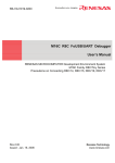
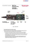
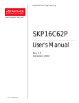
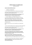
A pplica t io n s E n g in e e r in g Powerful Processors – Easy to Use™ SKP8CMini-13 User's Manual Rev. 1.0 October 2004 w w w.renesas.com MCU Applications Engineering Table of Contents 1.0 Introduction ...............................................................................................................3 2.0 Kit Contents...............................................................................................................4 3.0 Limited Guarantee and Support.................................................................................5 4.0 System Connectivity..................................................................................................6 4.1 Host Computer Requirements ...................................................................................6 4.2 Mini R8C Board .........................................................................................................5 4.3 ICD Board .................................................................................................................6 4.4 Development Tools ...................................................................................................6 4.4.1 HEW.......................................................................................................................6 4.4.2 NC30 C-Compiler/Assembler/Linker.......................................................................7 4.4.3 KD30 Debugger......................................................................................................7 4.4.4 FoUSB (Flash-over-USB™) Programmer ...............................................................7 5.0 Hardware...................................................................................................................8 5.1 Mini R8C Board .........................................................................................................8 5.1.1 R8C/Tiny Series of Microcontrollers .......................................................................9 5.1.2 Block Diagram ........................................................................................................9 5.1.3 External Battery Points .........................................................................................10 5.1.4 External Power Supply Points ..............................................................................10 6.0 System Operation & Limitations ..............................................................................11 6.1 Kernel (ROM Monitor) Introduction..........................................................................11 6.2 Pin Usage Limitations..............................................................................................11 6.3 Memory Map ...........................................................................................................11 6.4 Status After Reset ...................................................................................................12 6.5 Register Operation Limitations ................................................................................12 6.6 Limitations on Interrupts ..........................................................................................12 6.7 Stop Mode or Wait Mode Limitations .......................................................................13 6.8 User Program’s Real-Time Capability......................................................................13 6.9 Performing Debug Using Symbols...........................................................................13 7.0 Mini R8C Board Specifications ................................................................................14 7.1 Hardware Specifications..........................................................................................14 7.2 Operating Environment............................................................................................14 Appendix A. Troubleshooting Guide ..............................................................................15 A.1 USB Driver Problems ..............................................................................................15 A.2 KD30 Problems.......................................................................................................16 Appendix B. Reference Manuals ...................................................................................18 Appendix C. J1 & J2 Pin Assignment ............................................................................19 Appendix D. Board Dimensions.....................................................................................20 Appendix E. Expansion Circuit ......................................................................................21 Appendix F. Schematic and Bill of Materials..................................................................22 Appendix G. In-Circuit Debugger...................................................................................22 SKP8CMINI-13 User’s Manual Rev. 1.0 October 2004 MCU Applications Engineering 1.0 Introduction The SKP8CMINI-13 Starter Kit Plus (SKP) is a compact system to evaluate Renesas software development tools and the R8C/Tiny microcontrollers (MCU). The kit also includes sample code, documentation, and tutorial to jumpstart development. The software development tools that come with the kit include the High-performance Embedded Workshop HEW, R8C/Tiny version of NC30WA C-compiler/Assembler/Linker (NC8C), KD30 Debugger, and FoUSB (Flash-over-USB™) Programmer. The KD30 Debugger, together with the In-Circuit Debugger (RTA-FoUSB-MON), provides a realtime, source-level debug environment. The FoUSB Programmer application, with the In-Circuit Debugger (ICD), allows in-system programming of the R8C/Tiny flash MCU. The ICD provides a convenient USB (Universal Serial Bus) interface between the Mini R8C board and the PC. This interface reduces resource requirements on the R8C/Tiny MCU, allows faster code downloads and, can also be used to program other Renesas Flash MCUs using Flash-overTM. USB SKP8CMINI-13 User’s Manual Rev. 1.0 3/22 October 2004 MCU Applications Engineering 2.0 Kit Contents This section describes the contents of SKP8CMINI-13 product package. When unpacking your kit, please check to see that all products listed below are included. 2.1 SKP8CMINI-13 Starter Kit Plus (SKP) Product List Table 2-1 lists the products included in the kit. Table 2-1 SKP8CMINI-13 Product List Product Name Mini R8C Board In-Circuit Debugger (RTA-FoUSBMON) 6’ Mini USB Cable CD ROM Qty 1 1 1 1 Remark R8C/Tiny target board KD30 Debugger/ FoUSB Programmer Interface Board ICD to PC Auto-install program HEW3 Embedded Workshop NC8C Compiler/Assembler KD30 Debugger FoUSB Programmer Manuals Sample programs 2.1.1 CD-ROM The CD-ROM contains the electronic manuals and software necessary for developing programs. Your computer must have Netscape Navigator or Microsoft’s Internet Explorer to view the help files and Acrobat Reader to view the manuals. Insert the enclosed CD into your computer and SKP installer will auto-start. The SKP installer program will create a C:\MTOOL and C:\MTOOL\SKP8CMINI13 folder on your machine. Development tools can be found under C:\MTOOL (NC30WA Compiler, KD30 Debugger, and FoUSB Programmer) or C:\Hew3 (HEW High-performance Embedded Workshop). Documentation, sample code, and other SKP related files could be found under the C:\MTOOL\SKP8CMINI13 folder. If the SKP installer program does not start up, browse the CD’s root folder and double-click on ‘SKPInstaller.exe’ to start installation. SKP8CMINI-13 User’s Manual Rev. 1.0 4/22 October 2004 MCU Applications Engineering 3.0 Limited Guarantee and Support Renesas Technology America, Inc., warrants the SKP8CMINI-13 Starter Kit Plus to be free from component or assembly defect for a period of 180 days from the date of purchase. Settlement is limited to repair or replacement of the product only. Renesas Technology America, Inc., does not assume any liability arising out of the application or use of any product, circuit or procedure described herein. No other liability or warranty apply, expressed or implied. Software warranty is limited to replacement of the CD only. While every attempt has been made to ensure accurate documentation, Renesas Technology America, Inc., cannot be held responsible for error or omissions and reserves the right to make changes without further notice. “Flash-Over-USB” is a trademark of Renesas Technology America, Inc. All trademarks are the property of their respective owners. SKP8CMINI-13 User’s Manual Rev. 1.0 5/22 October 2004 MCU Applications Engineering 4.0 System Connectivity The following lists the hardware and software products required for using the SKP8CMINI-13 Starter Kit Plus. • • • • • Host Computer with available USB port (supplied by user) Mini R8C Board In-Circuit Debugger (RTA-FoUSB-MON) Mini USB Cable Software Tools (HEW3, NC8C Compiler, KD30 Debugger, FoUSB Programmer) Figure 4-1 shows the system connectivity for the SKP8CMINI-13. Figure 4-1 SKP8CMINI-13 Connectivity 4.1 Host Computer Requirements The minimum requirement to be able to use the software that comes with the kit is a PC with an available USB port and Microsoft Windows 98, ME, 2000, or XP operating system. 4.2 Mini R8C Board The Mini R8C board provides a compact evaluation and development environment for the R8C/Tiny series of MCU. It has two switches (pushbutton and slide) and LED’s for user interface. It also has a CdS cell and thermistor on board. 4.3 In-Circuit Debugger The ICD provides a plug-and-play debugging and programming interface to the Mini R8C board by using the host computer’s Universal Serial Bus (USB). The USB port also provides power to the Mini R8C board and ICD thereby eliminating the need for an external power supply. NOTE: The ICD can be used to connect to other boards (i.e. customer target boards) with an R8C or M16C Flash MCU. For details, please see ICD User’s Manual included with the kit (Start > All Programs > RENESAS-TOOLS > SKP8CMINI13 > Document Descriptions). 4.4 Development Tools Aside from SKP documentation and sample code, the SKP installer program also installs the development tools. Please see the quick start guide on how to run the SKP installer. 4.4.1 HEW SKP8CMINI-13 User’s Manual Rev. 1.0 6/22 October 2004 MCU Applications Engineering The High-performance Embedded Workshop (HEW) provides an Integrated Development Environment (IDE) and Graphical User Interface (GUI) that integrates the software development tools and provides project management features. 4.4.2 NC8C C-Compiler/Assembler/Linker The kit is supplied with a special R8C version of Renesas’ NC30WA C-compiler. NC8C generates debug information files from C language and the assembly language source files. NC8C limitations include: • • No support or warranty. Total program ROM size less than 64 Kbytes. Please see the NC8C Release 1 Release Note (R8C/Tiny only version) for complete specification limitations. 4.4.3 KD30 Debugger KD30 is a remote debugger that runs on the host PC. While communicating with the monitor program, the debugger provides a highly efficient evaluation environment. KD30 features include: • • • • Source-line debug for assembly language, structured assembly language, C language Run command with 2 breakpoints RAM monitor function C variable “watch” window 4.4.4 FoUSB (Flash-over-USBTM) Programmer User programs can run on the Mini R8C board without the host computer running KD30 by programming the on-board R8C/Tiny flash MCU with firmware using FoUSB Programmer software and ICD. It can also be used to program other Renesas R8C and M16C Flash MCU’s. SKP8CMINI-13 User’s Manual Rev. 1.0 7/22 October 2004 MCU Applications Engineering 5.0 Hardware 5.1 Mini R8C Board Figure 5-1 shows the Mini R8C Board with major components identified. CdS Cell External Battery Points** 18-pin I/O Header J1 Thermistor R8C/13 R8C/11 R5F21134FP R5F21114FP Slide Switch S1 20MHz Crystal Pushbutton Switch S2 3 User LED's Clock Stop Detect Jumper JP3 16-pin I/O Header J2 MCU Power Jumper JP1 J3 ICD External Power Supply Points* J4 E7*** Figure 5-1. Mini R8C Board SKP8CMINI-13 User’s Manual Rev. 1.0 8/22 October 2004 MCU Applications Engineering Note: * Connect an external power supply to these points to power the board when not using the ICD. ** Use this jumper (JP2) when connecting batteries or an external supply to power to the add-on on-board voltage regulator. The bottom side of the board can be populated with a voltage regulator circuit and battery holder for stand-alone operation. See Appendix G for more information. *** E7 connector is not assembled on the SKP8CMINI-13. 5.1.1 R8C/Tiny Series of Microcontrollers The R8C/Tiny Series of 16-bit single-chip, flash microcontroller (MCU) is available in several configurations of peripheral functions and features. A Hardware Manual for the R8C/13 group of microcontrollers can be found on the C:\MTOOL\SKP8CMINI13\Docs folder of your PC under the filename ‘r8c13_hardware_manual.pdf’ after SKP software installation or from the Start menu (Start > All Programs > RENESAS-TOOLS > SKP8CMINI13 > Document Descriptions). 5.1.2 Block Diagram The Mini R8C Board incorporates an R5F21134FP (32 pin LQFP) from the R8C/13 group of microcontrollers. Figure 5-2 shows the Mini R8C Board block diagram. 20MHz S1 CdS cell Thermistor R22 RT1 S2 JP3 P1_3 To FoUSB-ICD To E7 J3 P4_5 Xin Xout U1 U1 R5F21134FP R5F21114FP MCU MCU SIO+ J4 JP1 Vcc Kernel (ROM Monitor) AN1 AN0 Red LED Yellow LED Green LED D1 D2 D3 P1_0 P1_1 P1_2 MCU Power for Icc Measurements Ports J1, J2 Headers Figure 5-2. Mini R8C Board Block Diagram SKP8CMINI-13 User’s Manual Rev. 1.0 9/22 October 2004 MCU Applications Engineering 5.1.3 External Power Supply Points The external power supply points can be used to operate the Mini R8C Board without power from the ICD. This is a direct connection with Vcc and Ground on the board. Please see the schematic in Appendix C. An external power supply that can provide 2.7V to 5.5V and 100mA can be used. However, when used with the ICD (in target power mode), 3.3V is the minimum voltage for proper operation. 5.1.4 External Battery Points (using on-board voltage regulator circuit) An external battery (or power supply) can be connected to JP2 for operation with the voltage regulator circuit. The Mini R8C Board has provisions for a voltage regulator circuit but does not come with this circuit populated. For more information please see the schematic in Appendix C and expansion circuit description in Appendix G. SKP8CMINI-13 User’s Manual Rev. 1.0 10/22 October 2004 MCU Applications Engineering 6.0 System Operation & Limitations The kit provides sophisticated debugging features at a low cost but it does have some limitations when used with KD30 Debugger and ICD. Section 6.1 introduces the ROM monitor program and how it is used. The limitations when this ROM monitor is running with the user program are listed in table 6-1. Table 6-1 Systems Limitations During Debug (when used with ICD + KD30) Item Please Refer To 6.2 Pin Usage Limitations 6.3 Memory Map User Limitations 6.4 Status After Reset 6.5 Register Operation Limitations 6.6 Limitations on Interrupts 6.7 Stop or Wait Mode Limitations Debugger Limitations 6.8 User Program’s Real-time Capability 6.1 Kernel (ROM Monitor) Introduction During debug (used with the KD30 debugger), a small program, called a kernel, is downloaded to the R8C/13. The kernel communicates with the KD30 Debugger through the ICD about MCU status during user code debugging operations. There are no special steps required in the user program to make use of the ICD. The operation of the kernel is transparent to the user but there are some limitations and these are discussed from section 6.2. After starting KD30, the ICD downloads the kernel to the R8C/13 if it does not exist (e.g. blank device or programmed with FoUSB Programmer). After downloading the kernel, KD30 opens the Program Window and the R8C/13 is ready for downloading code. Connecting the ICD without starting KD30 will not affect the lines connected between the ICD and the R8C/13 – the ICD keeps the lines in high-impedance state. The ICD only drives the pins after KD30 or FoUSB Programmer is started. After program debug and verification, you can then create and download a binary, Intel (.hex) or Motorola (.mot), file to the R8C/13. This operation erases the kernel and only leaves the user program. 6.2 Pin Usage Limitations SIO/UART1 pins are used for communication between the Mini R8C board kernel and the host computer through the ICD. Do not connect these pins to any other pins. UART1 cannot be used in the user program. For details, please see ICD (RTA-FoUSB-MON) User Manual Section 5, Target M16C ROM Monitor Resources. 6.3 Memory Map Figure 6-2 shows the R5F21134FP memory map. The user memory area includes: • RAM area – 1K Bytes • Flash ROM area – 14 KB SKP8CMINI-13 User’s Manual Rev. 1.0 11/22 October 2004 MCU Applications Engineering 00000h 002FFh SFR Area 00400h 007FFh Monitor RAM Area - 128 Bytesprograms Note: User Internal RAM Area - 1KB not use shaded area. 02000h 02FFFh must Monitor Program Data Flash ROM Area - 4KB 0C800h User Program Area - 14KB 0C000h Flash ROM Area - 16KB 0FFDCh 0FFFFh Fixed Vector Area Figure 6-2 R5F21134FP Memory Map Note there are no limitations regarding user RAM however, 2k bytes of user Flash ROM are utilized by the kernel. 6.4 Status After Reset Table 6-2 lists the value of the UART1 register initialized by the kernel when the Mini R8C starter board is reset. The register status depends on the MCU’s internal operation performed after a reset. Table 6-2. Initial Register Values After Reset Register Name Initial Value After Reset UART1 Set for external clock synchronous mode 6.5 Register Operation Limitations Table 6-3 lists registers with modification limitations. Modifying the contents of these registers are modified may cause the kernel to operate incorrectly. Table 6-3. Limitations on Register Operation Register Name UART1 Transmit/Receive Mode Register UART1 Transmit/Receive Control Register 0 UART1 Transmit/Receive Control Register 1 UART1 Interrupt Control Register 0 UART Transmit/Receive Control Register 2 UART1 Transmit Buffer Register UART1 Receive Buffer Register Do not change Restriction Do not change Do not change bits 0 and 2 Do not write to this register Do not read this register 6.6 Limitations on Interrupts - Vectors that reside in the Hardware Vector Table Table 6-4 lists the limitations on hardware interrupt vector addresses. SKP8CMINI-13 User’s Manual Rev. 1.0 12/22 October 2004 MCU Applications Engineering Table 6-4. Interrupt Vector Addresses Interrupt Cause R8C/13 Vector Address Undefined 0FFDCH ~ 0FFDFH Overflow 0FFE0H ~ 0FFE3H BRK Instruction 0FFE4H ~ 0FFE7H Address Match 0FFE8H ~ 0FFEBH Single-step 0FFECH ~ 0FFEFH Watchdog Timer 0FFF0H ~ 0FFF3H Reserved 0FFF4H ~ 0FFF7H Reserved 0FFF8H ~ 0FFFBH RESET 0FFFCH ~ 0FFFFH Kit Specification User available User available User available User inhibited User inhibited User available Reserved Reserved Reset vector (Note 1) NOTES: (1) The monitor program transparently relocates the Reset vector to FFFD8H. 6.7 Stop or Wait Mode Limitations To use Stop or Wait modes in the user’s program, start the debugger in free-run mode. If you want to debug, close the RAM, C Watch and ASM Watch Windows before actually debugging. Furthermore, set a breakpoint or take other necessary measures when getting out of Stop or Wait mode in order to ensure that no windows operations will be performed until the program stops at the breakpoint. 6.8 User Program’s Real-Time Capability Please be aware that, even if the kernel stops the user program (kernel in “STOP” state), the hardware peripherals will continue to run. Therefore, interrupts may not be serviced properly. While the user program is running (kernel is in “RUN” state), there is no overhead on the application code, UNLESS a RAM monitor window is open in KD30. This window requires periodic communication with the MCU. This communication suspends normal application operation while servicing the request (approximately 2000 BCLK cycles for each 16 bytes of data displayed in the window are used per window update). 6.9 Performing Debug Using Symbols • Normally when a new project is started, debugging symbols are enabled. If you are unable to debug your program using symbols in KD30, add the debug option [-g] before compiling the programs. For more information, see the HEW user’s manual. SKP8CMINI-13 User’s Manual Rev. 1.0 13/22 October 2004 MCU Applications Engineering 7.0 Mini R8C Board Specifications 7.1 Hardware Specifications Table 7-1 lists the specifications of the Mini R8C Board. Table 7-1. Mini R8C Board Specifications Item Specification MCU R5F21134FP Clocks Main Clock: 20MHz Crystal Memory (Internal) RAM: 1 KB Flash ROM: 16KB (14KB user) + 2k x2 Data Flash Connector [J1 & J2]: Expansion connectors [J3]: Debugger interface Sensors [R22]: CdS Cell connected to AN1 (P06) [RT1]: Thermistor connected to AN0 (P07) Jumpers [JP1]: MCU power – for MCU Icc measurements [JP2]: External battery or power supply connection [JP3]: Oscillation Stop Detect function Switches [S1]: Slide switch (connected to P13) [S2]: Pushbutton switch (connected to P45) LED’s [D1] (Red): User output (connected to P10) [D2] (Yellow): User output (connected to P11) [D3] (Green): User output (connected to P12) 7.2 Operating Environment Table 7-2 lists the environmental conditions for using and storing the Mini R8C board. When storing the board, place it in a conductive bag and then in the packing box your product was shipped in from the factory. Table 7-2. Operating Environment Environmental Condition Ambient Temperature Operating 0 - 55°C (No corrosive gas allowed) Storage -30 to 75°C (No corrosive gas allowed) SKP8CMINI-13 User’s Manual Rev. 1.0 14/22 Ambient Humidity 30 to 80% (non-condensing) 30 to 80% (non-condensing) October 2004 MCU Applications Engineering Appendix A. Troubleshooting Guide This section discusses possible problems you may encounter while installing the software (and drivers) and while running the KD30 or FoUSB Programmer applications. This section also discusses the countermeasures and solutions to resolve these problems. If, for any reason, you cannot resolve the problem, please contact your Renesas representative for assistance. A.1 USB Driver Problems This section discusses the usual problems with the driver installation and how to fix it. The most common problem encountered is that Windows did not properly install the driver and so the ICD is not recognized. This may also cause the device status to indicate that the device is not working properly. An indication of this problem is the ICD status yellow LED - it blinks about 2-3 times a second. When the driver is installed properly, the yellow LED should only blink every second. Before trying the following steps, try restarting your PC and see if this resolves the problem. You can check the status using the Device Manager. If the ICD appears under the Universal Serial Bus Controllers with NO red X or yellow exclamation point, the driver was installed properly. If you are using Windows 2000 or Windows XP, you need to have Administrator privileges to be able to install the drivers. For cases where the ‘Device Status’ states the device is not working properly, please try the following: • • • • • Double-click on ‘Renesas USB-Monitor’ and a Renesas USB-Monitor Properties dialog box appears. Click on ‘Driver’ tab and click on ‘Update Driver’ button. Select ‘Display a list…’ and click on ‘Have Disk’ button. Specify and locate the ‘C:\MTOOL\FoUSB\USB Drivers’ folder on your PC and install ‘usbmon.sys’ driver. If this process does not work, please try the instructions below. For cases where in the driver was not installed properly by Windows (Windows 98, Windows 2000) or not listed in the Device Manager > Universal Serial Bus Controllers, please try the following: • • • Unplug the USB Cable so Windows removes driver from memory. Delete the driver ‘usbmon.sys’ from ‘\WINNT\SYSTEM32\DRIVERS\ folder in Windows 2000 or \WINDOWS\SYSTEM32\DRIVERS folder in Windows 98. Plug in ICD and try installing the driver as written above, but use the driver from the CD. The folder is C:\MTOOL\FoUSB\USB Drivers. SKP8CMINI-13 User’s Manual Rev. 1.0 15/22 October 2004 MCU Applications Engineering A.2 KD30 Problems This section discusses the cause of the problem and countermeasures to resolve it. The common problems encountered with KD30 are: • USB option cannot be selected from the initialization screen • Cannot connect to target • KD30 already exists • Issues that may come up during debug operations A.2.1 USB Option Unavailable When USB cannot be selected from KD30’s Init dialog box, you might be using an old version of KD30 that does not support USB. Uninstall this version of KD30 and install latest version of KD30 from the \Tools\KD30 directory of the SKP CD. A.2.2 Cannot Connect to Target When the message ‘Can’t connect with the target’ is displayed after KD30 startup, there are several reasons that may cause this message to appear. Each cause and the corresponding countermeasure are discussed below. • The SKP is not connected correctly. Please connect the ICD to your PC. Note: Regardless of whether the ICD is bus or targetpowered, please connect target board to ICD board first before plugging the USB cable to your PC. Please see section 4 on system (SKP8CMINI-13) connectivity. • The ICD has no power (Power LED on ICD is off). Please ensure that the Power Mode switch on the ICD is on the ‘USB’ side. In ‘Target’ position, the ICD is powered from the target side. • USB was not selected on the Init dialog box. Please select ‘USB’ from the Init dialog box that is displayed right after you start KD30. • The selected MCU on the ICD board and the actual target MCU (R8C/13) do not match. Close the error message by clicking on ‘OK’ button, and then click on the ‘Cancel’ button of the KD30 Init window to close KD30. Make sure you select ‘R5F21134.mcu’. If the MCU loaded on the ICD is different, KD30 will re-program the ICD to match it. • The target MCU is damaged. Try a different target board and see if KD30 will come up as you may have a damaged board or MCU. SKP8CMINI-13 User’s Manual Rev. 1.0 16/22 October 2004 MCU Applications Engineering A.2.3 KD30 Already Exists When a message ‘KD30 already exists’ is displayed, the usual cause of this problem is that the KD30 application was not properly closed. Please check if KD30 is already running by looking at your task bar. If KD30 cannot be found there, bring up Task Manager (press CTRL-ALT-DEL once to display the ‘Task Manager’). Select KD30.exe on the ‘Processes’ list and click on ‘End Process’ to terminate KD30. A.2.4 Issues that may come up During Debug Operations While using KD30 to debug user code, some issues may come up because the limitations discussed in section 6 were not satisfied. These common issues are listed on table A.2, including the countermeasures. Table A.2. Problems while using KD30 Problem Possible Cause/s and Solution After stepping a few • Changes were made to UART1 SFR’s. instructions, KD30 hangs Breakpoints do not seem to • KD30 is in “free RUN” mode. From the “Init” window work (Environment > Init), change RUN mode to “Sample Mode”. KD30 locks up (cannot stop • Changes made to UART1 SFR’s. program) or • Ensure no limitations in Section 6 were violated. Communication error • Re-initialize the system without closing KD30. See note message is displayed. below. • Do a hardware reset. User-program runaway may be corrupting the kernel (RAM, interrupt vectors, flags, etc.) Close KD30, hit reset button on the SKP8CMINI to reset the board, and then restart KD30. Download problems • Filenames or directory names contain spaces or special characters. • HEW project not properly set up (startup files missing or out of order, files added to wrong member, etc). Try creating a new project and adding your source files to it. For details, please see HEW user’s manual. To re-initialize the system without closing KD30, try the following: • • • • Press the [OK] button on the error dialog box to close it. When an Exit dialog box appears, press the [Cancel] button to close it. Hit reset button on the SKP8CMINI-13 board. Press KD30 reset button. After initialization, debugging can resume. However, it is recommended that you download your program again before debugging. Note: If it has been identified that there are problems with the ICD, please see the ICD’s (RTAFoUSB-MON) user’s manual and troubleshooting. SKP8CMINI-13 User’s Manual Rev. 1.0 17/22 October 2004 MCU Applications Engineering Appendix B. Reference Manuals Item Title Description 1. Mini R8C SKP Quick-Start Guide 2. 3. 4. 5. 6. Mini R8C SKP User's Manual Mini R8C Board Schematic Mini R8C Board BOM R8C/13 Group Hardware Manual R8C Series Software Manual 7. HEW User's Manual 8. NC8C User’s Manual 9. AS30 User’s Manual 10. 11. KD30 User's Manual M16C/20/60 C Language Manual 12. M16C/20/60 Series Sample Programs 13. USB Monitor User's Manual SKP8CMINI-13 User’s Manual Rev. 1.0 18/22 Document that will help you get started on using the SKP8CMINI. Installation and operation guide for the SKP8CMINI. Schematic diagram for the Mini R8C board. Bill of materials for the Mini R8C board. Specifications for the R8C/13 MCU. This document details the instruction set and timing information for the R8C series CPU cores. High-performance Embedded Workshop User’s Manual. ANSI C-language programming guide for the R8C/Tiny and M16C series MCUs. Assembly language programming guide for the R8C/Tiny and M16C/20/60 series MCUs. Use Help utility within KD30 application. C Language Programming manual for M16C family MCUs. Sample programs and application notes for the M16C/20/60 and R8C series MCUs. User guide and operation manual for the ICD. October 2004 MCU Applications Engineering Appendix C. J1 & J2 Pin Assignment Pin No. 1 2 3 4 5 6 7 8 9 10 11 12 13 14 15 16 17 18 J1 Signal Pin No. 1 2 3 4 5 6 7 8 9 10 11 12 13 14 15 16 Vcc GND RESET CNVss P37/RxD1 MODE P00/AN7/TxD11 P01/AN6 P02/AN5 P03/AN4 P04/AN3 P05/AN2 P06/AN1 P07/AN0 P45/INT0 NC Vcc GND SKP8CMINI-13 User’s Manual Rev. 1.0 19/22 J2 Signal Xin/P46 Xout/P47 P30/TXout/CMP10 P31/TZout/CMP11 P32/INT2/CNTR1/CMP12 P33/INT3/TCin P10/KI0/AN8/CMP00 P11/KI1/AN9/CMP01 P12/KI2/AN10/CMP02 P13/KI3/AN11 P14/TxD0 P15/RxD0 P16/CLK0 P17/INT1/CNTR0 Vcc GND October 2004 MCU Applications Engineering Appendix D. Board Dimensions Mini R8C board dimensions are provided here for making connections to user defined add-on boards. SKP8CMINI-13 User’s Manual Rev. 1.0 23/25 October 2004 MCU Applications Engineering Appendix E. Expansion Circuit Additional wiring has been provided on the bottom side of the Mini R8C board to provide a battery powered, voltage regulated circuit. The schematic of appendix C details this circuit and the BOM in appendix D specifies all the parts. The data sheet for the voltage regulator is included on the SKP CD. The layout drawing is provided below. NOTE: Ensure that R4 is un-populated when the battery-regulator circuit is populated. SKP8CMINI-13 User’s Manual Rev. 1.0 21/22 October 2004 MCU Applications Engineering Appendix F. SKP8CMINI-13 Schematic and Bill of Materials The SKP8CMINI-13 Schematic is available as a separate document, SKP8CMINI13_Schematic.pdf. The SKP8CMINI-13 Bill of Materials is available as a separate document, SKP8CMINI13_BOM.pdf. Appendix G. In-Circuit Debugger For details on how to use the ICD, please see RTA-FoUSB-MON User’s Manual. SKP8CMINI-13 User’s Manual Rev. 1.0 22/22 October 2004