1
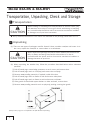
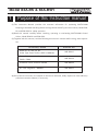
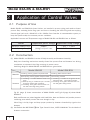
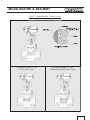
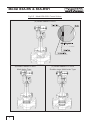
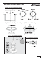
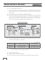
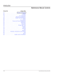
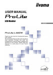
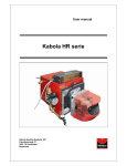
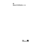
Bulletin No. MIE-B4301A
Bulletin No. MIE-B4301A
INSTRUCTION MANUAL
This catalogus is supplied for information purpose only and should not
be considered certified marketability and conformability of this prodct.
□ MOTOYAMA is continuously improving and upqrading its product design, specifications and/or
dimensions, Information included herein is subject to change without notice.
■ Head Office and Factory
5-2, Ohira Aza Kameoka, Ohhira-Mura, Kurokawa-gun, Miyagi-ken, 981-3697 Japan
TEL: + 81-22-344-4546 / FAX: + 81-22-208-5020
■ Tokyo Branch
4 F Nihon Seimei Tamura-cho Bldg., 4-1-9, Shinbashi, Minato-ku, Tokyo, 105-0004 Japan
TEL: + 81-3-6403-7782 / FAX: + 81-3-6403-7788
Printed in Japan
2011. 04. 500 TKP
Introduction
Thank your very much for choosing MOTOYAMA Control Valves.
To use this product safely and to optimize its performance, it is recommended that the following instruction should be read carefully and followed.
1 General
1 Keep this instruction manual in operator's hand.
2 Before using this Control Valves, read this instruction manual carefully and fully understand it for
operation.
3 This instruction manual does not cover the Accessories installed to the Control Valves.
Kindly refer appropriate Accessories' Instruction Manual along with this manual.
2 For Safety Use
To use this Control Valves safely, this instruction manual describes symbols and signal terms in accordance with JIS Z2901 and ANSI Z5351 which shall call your attention to keep safety manner or
to give caution of handling, together with notes. Important information has been marked and emphasized with the following symbols in this Instruction Manual.
Symbols &
Signal Terms
Explanation
A direct endangerment of a person's health or life may occur
if the Warning was not observed.
If the Caution was not observed, minor personal injuries and/or property damages may result.
WARNING
CAUTION
3 Note
MOTOYAMA is continuously improving and upgrading its product design, specifications and/or dimensions. Information included herein is subject to change without notice.
MOTOYAMA ENG. WORKS, LTD. SHALL NOT BE LIABLE FOR TECHNICAL OR EDITORIAL
ERRORS
OR
OMISSIONS
CONTAINED
HEREIN
;
NOR
FOR
INCIDENTAL
OR
CONSEQUENTIAL DAMAGES RESULTING FROM THE FURNISHING, PERFORMANCE, OR
USE OF THIS MATERIAL.
i
Transportation, Unpacking, Check and Storage
1 Transportation
CAUTION
When loading or unloading and transportation of Control valves, pay
full attention not to drop or not to give shock with hitting or bumping
etc. It would make the Valves and its accessories mechanical troubles
or damages as of precision instrument.
◆ If any cautions/instructions or care marks are indicated on the package, follow them as it is.
2 Unpacking
(1) There are two types of packages used for Control Valves, wooden crate/box and carton. In either case, unpack the crate/box or carton indoor or in warehouse.
CAUTION
Never unpack the package of Control Valves outdoor place where rain
falls, on damp and wet ground and/or where dust is in the air.
It would make the Valves and its accessories mechanical troubles or
damage because of precision.
(2) When unpacking the wooden box, follow the procedure described below unless otherwise
specified.
① Pull off round pegs around edge protectors at each corner and remove them.
② Pull off round pegs stuck on roof (top) and remove the roof (top).
③ Remove waterproofing materials, if applied, inside of the box.
④ Pull off round pegs stuck on frame at side and remove side plates.
⑤ Pull off round pegs stuck on frame at end and remove end plates.
⑥ If the goods are fixed with square-lumbers or bolts and nuts, remove them.
⑦ Remove waterproofing materials such as polyvinyl packing covering the goods.
[Note] T-form pegs are not required to be pull off when unpacking.
ii
3 Check of the Products
[Caution] After receiving the goods, unpack the packing promptly and check if the goods delivered are complying
with your order specification.
①
When taking out the goods from box, pay attention not to give any physical shock to the
Accessories attached to the Valves. Take out the spare parts if they are enclosed.
② Check the Name Plate attached to the Yoke of Actuator whether Valve specification complying
with your request.
③
If any clarification required on the received goods, please contact MOTOYAMA sales office
specifying Serial No. and Model Number indicating on Name Plate attached to the Valves.
4 Storage
①
If the goods need to be stored before installation, store the goods in warehouse or equivalent
indoor storage facility, covering whole the goods with cover like polyethylene sheet and protect
the goods from high temperature, moisture, dust and vibration etc.
CAUTION
During storage of the goods, protect Conduit connection of electrical
instrument from moisture or water which would give breakdown of the
electricity and cause trouble on the product.
② If the period of storage is exceeding one (1) year after delivery, re-calibration of the Valve action
and checking of gland and gasket leakage before installation must be made. Please contact
MOTOYAMA sales office when re-calibration is requested.
iii
CONTENTS
Page
1. Purpose of this Instruction Manual ………………………………………………………………… 1
2. Application of Control Valves
2. 1
Purpose of Use …………………………………………………………………………………
2
2. 2
Construction ……………………………………………………………………………………… 2
2. 3
Specification ……………………………………………………………………………………… 5
3. Installation
3. 1
General ………………………………………………………………………………………………6
3. 2
Installation on System Piping …………………………………………………………………
3. 3
Inspection after Installation …………………………………………………………………… 7
7
4. Operation, Check and Maintenance
4. 1
Precautions and Check before Operation …………………………………………………… 8
4. 2
Greasing to Gland Packing …………………………………………………………………… 9
4. 3
Check and Maintenance………………………………………………………………………… 10
5. Disassembling and Re-assembling
5. 1
Split of Actuator from Valve Body …………………………………………………………… 11
5. 2
Disassembling and Re-assembling of Valve Body ………………………………………… 12
6. Trouble Shooting ……………………………………………………………………………………… 22
7. Recommended Spare Parts ………………………………………………………………………… 24
8. Disposal of Control Valves and Parts ……………………………………………………………… 25
Reference Data <Estimated Life-Cycle of Control Valve parts> …………………………………… 26
iv
1
Purpose of this Instruction manual
(1) This Instruction Manual provides the essential information for optimizing MOTOYAMA
Diaphragm Actuated Seal-Ring Balanced Cage Guide Globe Type Control Valves, Model 83ABS and 83A-BSH for safety operation.
(2) Read this manual carefully before installing, operating or overhauling MOTOYAMA Control
Valves, Model 83A-BS and 83A-BSH.
(3) Together with this manual, read the following Accessories' manuals before using, when applicable.
Accessory Name
Bulletin No.
Model 01, 05, 83A, 83, 89
Globe Type Control Valves USER'S MANUAL
MIE-B3001
Electro-Pneumatic Valve Positioner
EA91A, EA90A
MIE-B6104
Pneumatic Valve positioner PA92A
MIE-B2008
Air Filter Regulator
MIE-B6903
MR2000
(4) If any other Accessories are installed on the Valves delivered, kindly request our sales office appropriate Instruction Manual, if necessary.
1
2
Application of Control Valves
2. 1
Purpose of Use
Model 83A-BS and 83A-BSH Control Valves are installed in process piping and used to Control
process flow, activating Valve Plug open and close or throttling the Valve Plug and seat replying
Control signal such as 4∼20mA DC or 20∼100kPa from Controller in instrumentation system, to
keep the specific and/or the constant process conditions.
Applicable Pressure and Temperature range of Model 83A-BS and 83A-BSH are as follows.
Model
Applicable press. Range
Applicable Temp. Range
83A-BS (for medium Temp.)
9.8MPa
(100kgf/cm2G)and lower
−50℃ ∼ +230℃
83A-BSH (for high Temp.)
2. 2
+500℃ and lower
Construction
(1) Model 83A-BS and 83A-BSH consist of Body Assembly and Actuator Assembly.
Body has Controlling mechanism actually Control the process flow and Actuator has driving
mechanism to activates Valve Plug receiving air power source.
Seal-Ring design for Model 83A-BS and 83A-BSH are given below.
Model 83A-BS
Materials
Structure
Model 83A-BSH
Seal-Ring: carbon graphite composite PTFE
Seal-Ring: Metal sintered carbon
Back-up Ring: carbon graphite composite PTFE
Tension-Ring: SUS316
① Seal-Ring is installed between Holder and
Cage.
② Back-up Ring is installed for port size 200
and larger together with Seal-Ring.
③ Seal-Ring seals guide clearance flow contact with Valve Plug sliding surface.
① Seal-Ring is installed in the groove of the
Valve Plug with Tension-Ring (inside).
② Seal-Ring seals guide clearance flow contact with guide sliding surface.
Fig. 2-1 (page 3) shows constructions of Model 83A-BS and Fig. 2-2 (page 4) shows Model
83A-BSH.
Body and Bonnet are jointed together with Stud Bolts, Nuts and Gasket and provide pressure
containing parts where process flow runs through or stay.
Valve Plug is led by Cage and keep proper position by Actuator Controlled by signal to the
Actuator.
(2) See Bulletin No. MIE-B3001 Globe Type Control Valves, USER'S MANUAL" for the details of
Actuator construction.
2
Fig.2-1
Model 83A-BS Control Valves
(a) Model 3883ACV-BS
(b) Model 3883ACS - BS
Multi-holes Type
(c) Model 3883ACS-L-BS
DoubleStage Multi-holes Type
3
Fig.2-2
Model 83A-BSH Control Valves
(a) Model 3883ACV-BSH
(b) Model 3883ACS-BSH
Multi-holes Type
4
(c) Model 3883ACS-L-BSH
Double stage Multi-holes Type
2. 3
Specification
See Catalog (Bulletin No. MCE-B4307) for detail specification of Model 83A-BS and 83A-BSH
Control Valves.
CAUTION
Do not use the products beyond the selected specification, code,
standard and/or regulations to secure the safety of the delivered products.
Model 83A-BS and 83A-BSH Control Valves have some limitation for usage because of Seal-Ring
materials. Following condition shall be reviewed before installation.
2. 3. 1
Model 83A-BS
CAUTION
Do not use the products for following services because carbon graphite composite PTFE is used for Seal-Ring material.
・ Food processing services
・ Oxygen services
・ Services where coloring is done or resin debris is a problem.
・ Acid at high-temperature and pressures(Aqua Regina, Nitric,
Sulfuric Acid)
・ Fluorine gas (F2), CIF3, OF2 etc. at high temperature.
・ Metal hydrides such as 80%KOH and B2H6.
Model 83A-BS may be applicable for above services by changing Seal-Ring material.
Please contact MOTOYAMA sales office for details.
2. 3. 2
Model 83A-BSH
Be sure to use the Valves under following condition because SealRing is made of metal sintered carbon.
①
CAUTION
②
Seal-Ring material is easy to be oxidized in oxidizing condition.
Service condition of the Valves shall be within the following temperature range.
*1. For oxidizing fluid
: 0∼+400℃
*2. For steam service and non-oxidizing fluid
: 0∼+500℃
Kindly check the availability of the Seal-Ring for the service of
strong acid fluids or chemicals higher than 100℃.
5
3
Installation
3. 1
General
Control Valves shall be installed in vertical to the piping line in general or Valve Stem shall be vertical to the ground.
①
Keep sufficient space to the Valves to be accessible to operate
safely and to make maintenance work, inspection and testing
easily.
② Eye-Bolts (Nuts) on Diaphragm case assembly must be used only
for hanging Actuator assembly. Do not hang up complete Valves
using Eye-Bolts after assembling Body and Actuator. In any case,
the following mass shall not be exceeded to hang up.
[Unit : kg]
Actuator
Model No.
3800
CAUTION
2800
Actuator
Size
Allowable
Hung Up Mass
Actuator Mass
N24
80
12
N28
150
15
N33S
150
24
N40
220
49
500 S/L
220
650 S/L
900 (Note 3)
270/275 (Note 2)
650X S/L
900 (Note 3)
365/395 (Note 2)
85/102 (Note 2)
【Notes】
(1) See catalogues for each Valves mass.
(2) Actuator mass is for direct action.
(3) Only when using four (4) Eye-Bolts for 650S/L and 650XS/L Actuator.
Other size of Actuator, allowable lifting load is permissible using two (2)
Eye-Bolts.
③
WARNING
6
Ambient temperature and humidity for the Valves should be
−20℃∼+70℃, and be less than 90% RH.
Never use the Valves on the service condition exceeding the rating
and the standard of connection to prevent the Valves from damage,
breakage and/or leakage.
3. 2
Installation on System Piping
(1) Remove all welding chips, scales and other foreign matters from internal of the piping line before installing the Valves in between.
(2)
Be sure to match arrow mark on the Valve Body to the flow direction when installing.
(3)
Piping Gasket shall be installed properly not to be out into the Body bore diameter.
(4)
Be sure the concentricity and parallelism of the Valves inlet and outlet piping are correct.
Tighten Bolts and nuts equally. Be sure not to give the excessive stress to the Valves.
①
CAUTION
(5)
When tightening, be sure not to give excessive load (piping
stress) to the Valves which would cause damage, deformation
and leakage.
② Seat leakage would increase if Valves installed in-correct flow direction and durability of the Seal-Ring will be deteriorated. Do not
use Valves on services which create back pressure to Valve.
Blow off scales, rust and foreign matters in pneumatic piping by compressed Air before connecting pneumatic piping to the Actuator and accessories.
(6)
Refer to each instruction manuals for wiring the conduit of electric equipments.
(7) For Finned or Extension Bonnet Valves, do not cover Bonnet with heating or cooling insulation.
CAUTION
3. 3
Either Body or Actuator, or the both, should be supported by proper
way.
Inspection after Installation
(1)
Carry out leakage test to check leakage from the connection piping.
(2)
Check leakage from Gland or Gasket after test pressure is applied to the piping.
If any leakage is found, reduce the pressure and retighten Gland Nuts or Stud Nuts with
equally.
CAUTION
①
②
If more than 6 months past before starting operation of the system, retighten Gland Nuts before starting pressure tightness test.
After re-tighten Gland Nuts, reciprocate the Valves at least 10
times from fully open to fully close to fit Gland Packing for operation.
7
4 Operation, Check and Maintenance
4. 1
(1)
Precautions and Check before Operation
Spring range and Off-balance for Model 2800 series Actuator is adjusted properly to the required specification when shipped. Do not turn Adjusting Screw unless otherwise it should be.
(2) Before start operation, check Stem Nuts, Actuator Bolts and Nuts and other screws to be tightened. Re-tighten if necessary.
(3) Some Gland Packing might have leakage because of stress relaxation. Check the tightness of
Gland Nuts and re-tighten if necessary.
(4) When Lubricator is equipped on Bonnet (page 9 & 10), check if Grease filled enough. Be sure
to close the Stop Valve after filling the Grease. See Table 4-1 to select appropriate Grease for
each services. Please contact MOTOYAMA sales office when replacement Grease is required.
①
If more than 6 months past before starting operation of the system, re-tighten Gland Nuts before starting pressure tightness
test.
After re-tighten Gland Nuts, reciprocate the Valves at least 10
times from fully open to fully close to fit Gland Packing for operation.
②
CAUTION
Table 4-1
CLIMAX Co.
Maker
#650
#750
#1901
−29 ∼ +230
−40∼+260
0 ∼ + 300
+300 ∼ +450
Red
Blue
Black
Black
Color
Services
THREE-BOND Co.
#400
Grease No.
Operating Temp.(℃)
Grease
Amine
Chloride
Acetylene
Asphalt
Stem
Acid
Chlorine
Vinyl Chloride
Coke oven gas
General high
Alkali
Food
General Gas
Coal tar
temperature fluid
Alcohol
Bleach
Hydrocarbon
Steam
Ammonia Cyanide
Mineral Oil
Phosphorus
Co
Milk
Freon
Water
Brine
Paints
Sulfur
Shape
Stick
Stick
[Note] No Lubricator is installed for the services fluid temperature is lower than -40℃.
8
Stick
Bulk (Can)
(5) When Hand Wheel is mounted, be sure Handle is set to the Neutral" or auto operation position which does not restrain Valve opening.
(6)
Carry out loop test with the Controller to check that the Valves open or close smoothly.
CAUTION
4. 2
(1)
①
②
③
If the Valves must be heated up, increase the temperature and
pressure gradually without changing them rapidly.
Heating up speed shall be less than 100℃/Hr.
During heating up, be sure to avoid sudden operation.
Greasing to Gland Packing
To use Braided Packing, it is required to use Greases to elevate the sealing and lubricating
property on Valve Stem.
(2)
The greasing device to inject the Grease is called Lubricator.
Fig. 4-1 shows the construction of Lubricator.
(3)
①
To supply the Grease in routine work, follow the procedure below.
Turn the Handle clockwise to make the Spindle closed.
(If the Pressure Screw is removed holding the Spindle open, Grease may flow out reversely
by internal pressure from Valve Body.)
②
Take out the Pressure Screw from Cylinder.
③
Insert designated Grease from this open port.
Use the designated Grease specified on the Name Plate attached on Actuator
④
Compress the Grease into the Lubricator by the Pressure Screw.
⑤
Under compressing the Grease by Pressure Screw, turn the Handle counter-clockwise to
make the Spindle open. Then compress the Grease further by Pressure Screw. After compressing, turn the Handle clockwise and close the Spindle.
・Repeat above operation ③, ④, ⑤ several times and fill the Grease into the Connection
Pipe and Cylinder.
CAUTION
Do not fill the Grease to strong or to much to prevent over flow from
Bonnet Staffing Box or to prevent the damage of Gland Packing itself.
Pay attention the over flow from Staffing Box, Guide Bush and/or
Valve Stem when greasing.
⑥
Turn the Handle clockwise to make the Spindle closed and Greasing is completed.
⑦
After greasing, open and close the Valves several times (around 10 times) to create uniformed grease film between Gland Packing and Valve Stem.
9
Fig.4
Lubricator
No. Part Name
1
2
3
4
5
6
7
8
9
10
11
12
4. 3
Body
Bonnet
Spindle
Gland Nut
Handle
Washer
Lock Nut
Connection Pipe
Cylinder
Pressure screw
Gasket
O-Ring
For low pressure
(600LB and lower)
Check and Maintenance
To maintain maximum efficiency on your Control Valves, it is recommended to check or proceed
maintenance work as follows. (See Paragraph 6. Trouble shooting on page 20-21)
(1)
Daily Check
Check leakage, abnormal sound, vibration and/or hunting
(2)
Periodical Check ……………………………………………………………………… [Annually]
Check each parts of the Valves, re-tighten the Gland and replenish/replace Grease if necessary.
(3)
Overhaul ………………… [Body: Once in every 2 years, Actuator: Once in every 5 years]
Disassemble the Valves and check the internal parts. (See Chapter 5)
WARNING
10
When leakage is found from the Valve or piping, Do Not Touch or
Access to the fluid until the safety is confirmed by proper responsible
person.
5 Disassembling & Re-assembling
Following is recommended procedure to disassemble or re-assemble Valves.
①
②
CAUTION
③
④
⑤
⑥
5. 1
Please prepare following spare parts available before disassembling: Gland Packing, Gasket Packing, Seal-Ring (Model BS and
Model BSH) and Back-up Ring (Model BS).
Do not reuse the used Gland Packing, Gasket Packing, Seal-Ring
(Model BS and Model BSH) and Back-up Ring (Model BS).
Prepare required Tools in advance.
Never disassemble the Valves on system under existing inside
pressure or before cooling down of the Valves completely.
Do not turn the Valve Stem when the Valves are closed.
On Model 2800 spring diaphragm Actuator, Do Not Turn the
Spring Adjuster. Turning of Spring Adjuster makes the change of
Spring Range limit, upper and lower.
Split of Actuator from Valve Body (See. Fig. 5-1)
WARNING
To disassemble the Valves on system line, Close the line and Release
all the system pressure in advance.
(1)
Place fitting mark on each connecting parts before disassembling.
(2)
Hold the Valve Plug at full open position depressurizing the supply pressure to zero on direct
action Actuator or supplying Air pressure on reverse action Actuator.
(3)
Loosen Stem Nut and Pointer together and go
downward, then lock. On Actuator size N33 and larger,
Fig.5-1 Removing Actuator
lower the Locking Plate together.
Thread size of Valve Stem and Top Stem is as follows.
Actuator size
(4)
Thread
N28
M9, P1. 25
N33
M12, P1. 75
N40
M18, P2. 0
500
W3/4-10
650
W7/8-9
Pull down Valve Stem by turning Stem Nuts with pointer
downward from Top Stem.
(5)
Remove Yoke Bolts.
(6)
Pull up Actuator upright and split it from Valve Body.
11
5. 2
Disassembling and Re-assembling of Valve Body
To disassembling or re-assembling Valve Body, follow the procedure below. (See Fig. 5-2∼5-10).
Fig.5-2
12
Model BS Body details
Fig.5-2
Model BSH Body details
13
5. 2. 1
Disassembling Procedure
5. 2. 1. 1
Model BS
(1)
Remove Stud Bolt Nuts.
(2)
Pull up Valve Plug together with Bonnet upright and split it from Valve Body.
CAUTION
Be careful not to drop Holder !
Holder might coming up together with Valve Plug.
(3)
Loosen Gland Nuts and release the tension of Gland Packing.
(4)
Pull down Valve Plug from Bonnet.
(5)
Remove Gland Bushing, Gland Packing, Lantern Ring and Packing Ring from Bonnet
gland.
(6)
Remove Cage from Body. In case Holder is remain in Body, remove both Holder and
Cage.
5. 2. 2. 2
Model BSH
(1)
Remove Stud Bolt Nuts.
(2)
Pull up Valve Plug together with Bonnet upright and split it from Valve Body.
CAUTION
Be careful not to drop Holder !
Holder might coming up together with Valve Plug.
(3)
Loosen Gland Nuts and release the tension of Gland Packing.
(4)
Pull down Valve Plug from Bonnet.
(5)
Gently pull out Guide from Valve Plug when it is coming up with Valve Plug.
(6)
Remove Gland Bushing, Gland Packing, Lantern Ring and Packing Ring from Bonnet
gland.
(7) Remove Cage from Body. In case Holder is remain in Body, remove both Guide and Cage.
14
5. 2. 2
5. 2. 2. 1
Inspection of the Parts
Model BS
After disassembling, each parts should be cleaned and checked as follows.
(1)
Check seat surface of Valve Plug and Cage to be free from damage and/or deformation.
(2) Remove Seal-Ring from Holder, check Holder Groove to be free from damage and/or deformation.
(3)
Check Body and Bonnet wall thickness decreased. Check Body and Bonnet sealing surface of Gasket Packing and Gland Packing to be free from damage and/or deformation.
(4)
Check the appearance of Valve Plug, Stem, Holder, Cage and sliding surfaces of each
parts to be free from corrosion, erosion, damage and/or deformation.
If any damage and/or deformation are found on each parts, repair or replacement are required. To request repair or spare parts, be sure to inform MOTOYAMA sales office the
serial numbers of the Valves specified on the Name Plate.
5. 2. 2. 2
Model BSH
After disassembling, each parts should be cleaned and checked as follows.
(1)
Check seat surface of Valve Plug and Cage to be free from damage and/or deformation.
(2) Remove Seal-Ring and Tension-Ring from Valve Plug, check Valve Plug Groove to be free
from damage and/or deformation.
(3)
Check Body and Bonnet wall thickness decreased. Check Body and Bonnet sealing surface of Gasket Packing and Gland Packing to be free from damage and/or deformation.
(4)
Check the appearance of Valve Plug, Stem, Holder, Cage and sliding surfaces of each
parts to be free from corrosion, erosion, damage and/or deformation.
If any damage and/or deformation are found on each parts, repair or replacement are required. To request repair or spare parts, be sure to inform MOTOYAMA sales office the
serial numbers of the Valves specified on the Name Plate.
CAUTION
To clean or repair Valve Plug sliding surface of Model BS or Guide
sliding surface of Model BSH using fine sandpaper, use sandpaper
grade #240 or fine one.
Never use File or Grinder to repair these parts.
15
5. 2. 3
Re-Assembling Procedure
Model BS
Body size
Trim
Model BSH
150mm and smaller
200mm or larger
50 ∼ 350mm
See 5.2.3.1 (page 16)
See 5.2.3.2 (page 17)
See 5.2.3.3(page18,19)
Bonnet
See 5.2.3.4 (page20)
On model BS, two (2) methods of assembling procedure are recommended depend on trim size and weight.
CAUTION
① Be sure to apply anti-seize grease (NEVER-SEEZ or equivalent) on
Seal-Ring surface of the Gasket.
② For "Oil Free" requirement, apply Fluorine type grease (DAIFLOIL
or equivalent) slightly
[Note] NEVER-SEEZ : products of BOSTICK, DAIFLOIL : products of DAIKIN
5.2.3.1
(1)
Model BS Trim Assembling [Port Size 150mm or smaller (See Fig. 5-4.)]
Install Spiral Wound Gasket (A) on Body lower groove and Serrated Gasket (B) on Body
upper groove. Install Seat-Ring on Gasket (A).
(2)
Install Seal-Ring on Holder.
(3)
Install Holder onto Cage fitting to Valve Plug. Pay attention not to damage or deform the
Seal-Ring.
(4)
Lift up Valve Stem with Holder and insert it into Cage in the body.
(5)
Follow the procedure on Paragraph 5. 2. 3. 4 (1)∼(7) for further assembly.
①
CAUTION
Fig.5-4
16
②
Be sure to install Seal-Ring and Back-up Ring in correct direction.
If the direction is not correct, it is not possible to get good sealing. (See Fig. 5-7.)
Keep the assembling in order. If install Cage, Holder with SealRing into Body first and then install Valve Plug, it is very easy to
damage or deform Seat-Ring. (See Fig. 5-5.)
Assembling Procedure (Correct Way)
Fig.5-5 Assembling Procedure (Wrong Way)
5.2.3.2
Model BS Trim Assembling [Port Size 200mm or larger (See Fig.5-6.)]
(1)
Install Spiral Wound Gasket (A) on Body lower groove and Serrated Gasket (B) on Body
upper groove. Install Seat-Ring on Gasket (A).
(2) Put Back-up Ring and Seal-Ring into Holder in order.
(3) Insert Valve Plug and Stem assembly into Cage.
(4) Install Holder onto Cage fitting to Valve Plug. Pay attention not to damage or deform the
Seal-Ring.
(5) Follow the procedure on Paragraph 5. 2. 3. 4 (1)∼(7) for further assembly.
①
CAUTION
Fig.5-6
②
Be sure to install Seal-Ring and Back-up Ring in correct direction.
If the direction is not correct, it is not possible to get good sealing. (See Fig.5-7.)
Keep the assembling in order. If install Cage, Holder with SealRing into Body first and then install Valve Plug, it is very easy to
damage or deform Seat-Ring. (See Fig.5-5.)
Assembling Procedure (Correct Way)
Fig.5-5 Assembling Procedure (Wrong Way)
Valve size 200A and larger
Fig.5-7
Seal Ring orientation
17
5. 2. 3. 3
Model BSH Trim Assembling (See Fig. 5-11.)
CAUTION
(1)
On Model BSH, outer diameter of Seal-Ring is slightly larger than
inner diameter of the Guide.
Insert Seal-Ring alone into Guide first and be sure to fit the Seal-Ring
into the Guide correctly without any gap or too loose.
Also confirm the slit of Seal-Ring not to be open widely. (See Fig. 5-8.)
Install Spiral Wound Gasket (A) on Body lower groove and Serrated Gasket (B) on Body
upper groove. Install Seat-Ring on Gasket (A).
(2)
Install the Guide. Confirm whether Guide is fitting Cage properly.
(3)
Install Tension-Ring into the groove of Valve Plug. Then install Seal-Ring over the
Tension-Ring.
①
CAUTION
②
Install the slit of Tension-Ring and the slit of Seal-Ring opposite
position, 180 degree apart.
If two slits are installed in closed position, sealing efficiency
would be decreased. (See Fig.5-9.)
When install Seal-Ring to Valve Plug, do not open the slit too
much.
Just open to fit outside diameter of the Valve Plug.
Seal-Ring is easy to be broken if opened too much.
(4) Install Valve Plug together with Seal-Ring and Tension-Ring into Guide slowly. Pay attention not to deform Seal-Ring.
CAUTION
Seal-Ring slit is open slightly by Tension-Ring.
When insert Valve Plug into Guide, close Seal-Ring slit by fingers.
It may not possible to insert Valve Plug into Guide without closing
Seal-Ring slit and it may damage Seal-Ring itself. (See Fig.5-10.)
Please install the slit position of Seal-Ring to be rectangular against body flow direction. (See
Fig. 5-12.)
(5)
18
Follow the procedure on Paragraph 5. 2. 3. 4 (1)∼(7) for further assembly.
Fig.5-8
Seal-Ring Check before Assembling
Fig.5-9 Orientation of Seal-Ring and Tension-Ring
Fig.5-11
Fig.5-10
Insert of Valve Plug
BSH Assembly procedure
Fig.5-12 Body and Seal-Ring poshition
19
5. 2. 3. 4
(1)
Assembling of Other Parts
Install Serrated Gasket (C) on Holder (Model BS) or Guide (Model BSH) and then install
Bonnet. Be sure Body, Cage, Valve Plug and Bonnet are installed correctly in straight and
in concentricity.
(2)
Apply anti-seize grease on Stud Bolts and tighten Nuts slightly.
(3) Be sure to check the smooth movement of Valve Stem up and down. Insert Gland Packing
one by one into Bonnet Gland with applying grease on it. (See Fig. 5-13 and Table 4-1 on
page 8 ) Be sure to install each Packing uniformly around the Stem. On braided Packing,
each cut end should be placed opposite position, 180 degree apart.
Fig.5-13 Gland Packing
PTFE V Packing
(4)
PTFE+Braid Packing
Braid Packing
Install Gland Bushing, Wiper and Gland Flange in order. Tighten Gland Nuts alternately
and uniformly. Required torque is as follows.
Unit: N-cm(kgf-cm)
Actuator size
PTFE V-Packing (+Braid Packing)
Braid Packing
N28∼N33S
100∼500 (10∼50)
200∼800 (20∼80)
N40∼650
150∼700 (15∼70)
1000∼2500 (100∼250)
[Note] Required torque is varies depend on type of Gland Packing, service condition, temperature and
pressure. This table shows standard torque for reference.
20
(5)
Install Stem Nuts and Pointer.
(6)
Tighten Stud Nuts alternately and uniformly.
(7)
Be sure to confirm the smooth movement of Valve Plug (Valve Stem) up and down.
①
CAUTION
When confirming Valve Plug movement up and down, be sure to
move within the range of rated lift of the Valves.
If Plug was lifted up too much, Seal-Ring may be damaged on
Model BS and Seal-Ring might be getting off from Guide on
Model BSH.
Pay attention not to move too much.
② When re-assembling, be sure to change all the Seal-Ring, Gland
Packing, Gasket Packing and Back-up Ring (Model BS) with the
new parts.
③ Pay attention not to damage Valve Plug sliding surface, Holder
groove inner surface and new Seal-Ring on Model BS. On Model
BSH, pay attention not to damage Guide sliding surface, Valve
Plug groove and a new Seal-Ring.
④ Never apply greases onto Seal-Ring for both Model BS and Model
BSH.
21
6
Trouble Shooting
Following is a list of general Troubles, Causes and Corrective Actions in routine operation of
Control Valves.
Table 6-1
Troubles
Valve fails to operate.
No signal nor supply air pressure
Vibration or Noise
Air pressure source (compressor) fault
Corrective action
Check compressor
Check Air piping
Clogged or leaking on Air piping
Check Air piping
Pressure Regulator Valve fault
Check and repair pressure Regulator
Controller fault
Check Controller
Clogged or leaking on signal Air piping
Check Air piping
Pilot Valve in Positioner fault
Check and repair Pilot Valve
Large leakage on Actuator
Check Actuator (Diaphragm)
Valve Stem or Guide stick
Disassemble Body and check, repair
or replace
Bend or breakage on Valve Stem
Repair or replace Valve Stem
Foreign matter entrapped on Seat or
between Guide clearance.
Disassemble and Check Valve port
Large clearance between Guide and
Plug
Repair or replace Valve Plug and
Guide
Loose connections (Valve Stem and
Valve Plug, Valve Stem and Top Stem,
Top Stem and Diaphragm).
Re-tighten connection
Poor de-aeration of fluid
De-aerate fluid
Flashing at outlet of the Valve Plug
Change Valve type
Plug chatter at almost fully
closed position
Fluid flow to close Valve Plug (flow
close)
Change Valve Cv or Plug and Control
position
Shock waves occur at Valve
outlet
Valve size too small (steam)
Enlarge Valve size
Insufficient Air source capacity
Add compressor
Pressure Regulator fault
Repair or replace pressure Regulator
Valve
Inappropriate resistance or volume of
Controller
Install Valve or volume tank in signal
circuit
Controller fault
Check Controller
Positioner fault
Check Pilot Valve
Tighten Positioner connections
Large friction on Valve Stem
Check and repair Valve Stem and
Guide
Large friction on Gland Packing
Replace Packing
Resonance with fluids turbulent wave
motion (fluctuations in stem's thrust
due to changes in fluid pressure)
Reduce differential pressure Change
Actuator, higher rigidity Install rectify
straight pipe on upstream
No supply Air pressure
No signal Air pressure
No Positioner output
Vibration and noise in all
range of opening
Supply Air pressure fluctuates
Valve fails to operate.
Presumed causes
Large leakage on Air piping
Valve no movement even Air
press is working on Actuator
22
Trouble Shooting
Signal Air pressure fluctuates
Neither supply Air nor signal
Air pressure fluctuates, but
Valve hunts
Too Slow Action
Troubles
Too slow stroke both direction
Too slow stroke, one way
Large hysteresis error
Valve no move beyond certain
travel
Large Leakage
Valve Stem fully closed position
Presumed causes
Control position changed,
range ability decreased
Leakage from Gland Packing
Disassemble and clean
Clogged guide with slurry or solids
Deteriorated
Packing
and
hardened
Change Valve type (Angle type)
gland
Change Packing and grease
Change Packing material
Thrust by large differential pressure to
Plug
Install Positioner
Actuator Air volume is big
Install Positioner or booster
Air leakage from Actuator
Check Actuator
Valve Stem and Guide, no alignment
Check Valve Stem alignment
Deteriorated
Packing
Change Packing
and
hardened
gland
Install big Actuator
Foreign matter entrapped in Valve
Plug
Disassemble and clean up
Clogged Valve Stem or Guide with
slurry or solid
Disassemble and clean up
Loose connection of Positioner or insufficient tightening
Re-tighten and re-adjust
Manual handle position is not set at
"NEUTRAL"
Set Handle position "NEUTRAL"
Lack of supply air pressure
Check supply air pressure
Corrosion, erosion or damage on
Valve Seat
Check Seat and repair or lap
Cavity in Valve Body
Repair or replace Body
Corrosion or erosion of Gasket (A)
Change Gasket
Abrasion deformation,
Seal-Ring
Impossible to move to fully
closed position
Corrective action
damage
of
Change Seal-Ring
Incorrect flow direction
Correct flow direction
Large differential pressure
Increase actuator power
Foreign matter entrapped in Valve
Plug
Disassemble and clean up
Guide or port seizure
Repair or replace damaged parts
Corrosion or erosion of Valve Plug or
Cage
Change Valve Plug or Cage
Loose gland Nut
Re-tighten uniformly
Deteriorated and hardened Gland
Packing
Change Packing. Change Packing
material
Incorrect insert of Gland Packing
Re-insert correctly
No Grease
Add Grease
Corrosion, erosion or damage of Valve
Stem
Repair or change Valve Stem
[Caution] If any improvement can not be made even by taking above mentioned corrective actions, Please contact our
sales office for further solution.
23
7
Recommended Spare Parts
(1)
All the parts of Control Valves are designed and manufactured utilizing Motoyama's flow
Control technology accumulated over past years. To continue stable operation of Control
Valves, it is recommended that the following genuine parts should be changed periodically
as recommended in Table 7-1.
Table 7-1
Component
Overhaul Internal and Recommended Spare Parts
Replacement Part
Disassembling
Interval
Replacement Interval
2years
Change the parts when disassembled.
Tension-Ring (BSH Type) may
not need to be changed every 2
years. (same as BP Type)
5years
Check and change when necessary.
Gland Packing
Gasket Packing
Body
Seal-Ring
(Model BS and Model BSH)
Back-up Ring (Model BS)
Diaphragm
Daisthread○
Daistat○
O-Ring
Seal-Packing
Dust Seal
R
R
Actuator
(2) When ordering spare parts, be sure to inform us the Parts Name and the serial numbers of
the Valves which is specified on the Name Plate.
CAUTION
24
Be sure to use the Genuine Parts only.
Also use the specified Grease described in this manual.
◆MOTOYAMA has no responsibility for the troubles in-correct or imitated parts and grease were used.
8 Disposal of Control Valves and Parts
①
WARNING
Be sure to blow out all the pressures and fluids left in the piping
line before dismounting the Control Valves.
② When harmful fluid remains in the body of the dismounted Valve,
disassemble the Body (See Para 5 on page 10) and clean up internals.
◆ Otherwise, human accident or environmental pollution may be induced.
(1) Basically, Control Valves component parts do not contain any harmful materials for pollution.
When necessary, scrap Control Valves as general metal-discarding materials.
(2)
When there is any discarding restriction for asbestos material, check the Model number of
Gland Packing and Gasket on the Name Plate, and if it is confirmed as asbestos type, take
the Gasket and Gland Packing out from the Body, then, discard it separately from other
metal parts.
25
Reference Data
Estimated Life Cycle of Control Valve Parts
Generally, estimated life cycle of Control Valves component parts are shown in following table.
Whereas, the life of each parts differ by temperature, pressure, frequency or operation and environment in service. It is recommended to use this table for reference for your consideration.
Accordingly, please be noted that estimated life cycle below do not mean the warranty value by
MOTOYAMA. Motoyama's general warranty period for Control Valves is one (1) year after shipment.
Estimated Life Cycle of Control Valves Parts
Part
No.
Valve Body
Actuator
Life Cycle
Notes
10years
Change Body if wall thickness decreased to 90% of
designed value
Body
2
Bonnet
3
Valve Plug
5
4
Cage
5
Holder (Model BS)
5
Guide (Model BSH)
5
Change when there is a change in the Seal-Ring
clearance (more than +0.05mm greater than spec)
6
Seal-Ring
2
Change on every overhaul
7
Back-up Ring
(Model BS 200mm and larger)
2
Change on every overhaul
Tension Ring (Model BSH)
5
Change when any damage found
8
Valve Stem
5
(Valve Plug is welded to Stem)
9
Gland Flange
10
10
Stud Bolt
5
Same for Nut
11
Gland Bolt
5
Same for Nut
12
York Bolt, York Nut
10
13
Gasket
2
Change on every overhaul
14
Wiper
5
Change when any damage or scratch found
15
Gland Bushing
10
16
Gland Packing
2
17
Lantern Ring
10
18
Packing Ring
10
19
Yoke
10
20-1
Diaphragm Case
10
20-2
Diaphragm Cover
10
21
Diaphragm Stem
10
22
Diaphragm Plate
10
23
Diaphragm Rubber
10
Change when any damage found
24
Spring
10
Same as above
25
Spring Seat
10
26
Adjustment Screw
5
27
Adjustment Guide
5
28
Seat Bearing
29
Daistat○, Daisthread○
5
Change on every overhaul
30
Dust Seal, O-Ring, Seal-Packing
5
Same as above
5
26
Part Name
1
10
R
Change when clearance became +0.1 mm larger
than design value
Change on every overhaul
5
R
Control Valve Parts Name and Construction
Parts number on below sketch is the number of the Table "Estimated Life Cycle of Control Valve
Parts", page 24.
[Note] Some parts for reveres action type are not shown on the sketch.
See page 14 for details.
【Direct Action Actuator】
Model BS
Model BSH
This manual is supplied for information purpose only and should not be
considered certified marketability and conformability of this product.
27