1
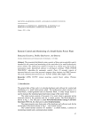
Design, Monitoring and Operation of Adaptive Networked Embedded Systems D4.4 Implementation of ANES Tool Chain: SW Prototype and User Manual ® The DEMANES Consortium Joint Undertaking Grant agreement: 269334 DOCUMENT INFORMATION Project Number Acronym 295372 DEMANES Full Title Design, Monitoring and Operation of Adaptive Networked Embedded Systems Project URL http://www.demanes.eu Document URL Artemis JU Project Officer Patrick Vandenberghe Deliverable Number D4.4 Title Implementation of ANES Tool Chain: SW Prototype and User Manual Work Package Number WP4 Title Tool Chain Date of Delivery Status Nature Contractual 24 Actual 26 Version Final 1.04 Dissemination level PU Author (partners) Responsible author Abstract (for dissemination) Name Willem van Driel Julio de Oliveira Filho Inmaculada Luengo Sergio Martinez Tommaso Mirante Marco Soddu Lauri Väätäinen (UEF) Email [email protected] Phone Partner Philips Lighting TNO H.I. Iberia Leitat Selex ES Akhela +358 40 355 2373 This document describes the implementation and usage of the ANES tool chain. The document gives installation instructions on the tool chain. Nowadays almost everything can be downloaded from the tool vendor’s site, so the document includes lot of URL links to help installation process. In addition, information on how to use DEMANES Design modelling language is provided. The aim of this section is to give an initial comprehension on the DEMANES modelling. The full details of the DEMANES modelling language is out of the scope of this document. However, full details are available in the deliverable of its own. The ANES tool chain is constructed using Open Source based and Commercially available tools. The data exchange between these tools is based on files. These files are using DEMANES XML format. The special generators are used to generate these files. Further, some parts of the application source code can be generated. The information on both generators is included. Keywords 2 / 58 DEMANES, ANES Tool Chain, User Manual, DEMANES Design process D4.4 Implementation of ANES Tool Chain: SW Prototype and User Manual ® The Consortium Artemis JU - GA: 269334 VERSION LOG 3 / 58 Date Author Modifications Version 25.3.2014 Lauri Väätäinen (UEF) Initial ToC, Short drafts for chapters 1 and 2. 00.00 1.4.2014 Lauri Väätäinen (UEF) Fixed ToC 00.01 19.5.2014 Lauri Väätäinen (UEF) Willem van Driel (Philips Lighting) Sergio Martinez (Leitat) Tommaso Mirante (Selex ES) Marco Soddu (Akhela) Included partner contributions, Finalizing 00.02 20.5.2014 Lauri Väätäinen (UEF) Version 1.0 01.00 22.5.2014 Lauri Väätäinen (UEF) Julio Oliveira De Filho (TNO) Included TNO’s contribution 00.03 22.5.2014 Lauri Väätäinen (UEF) New version 01.00 01.00 4.6.2014 Lauri Väätäinen (UEF) Willem van Driel (Philips Lighting) Inmaculada Luengo (H.I. Iberia) Fixes after the internal review 01.01 6.6.2014 Carla Cannas (Akhela) Lauri Väätäinen (UEF) QA review fixes 01.02 9.6.2014 Lauri Väätäinen Typos fixed 01.03 6.11.2014 Lauri Väätäinen Typos fixed 01.04 D4.4 Implementation of ANES Tool Chain: SW Prototype and User Manual ® The Consortium Artemis JU - GA: 269334 SUMMARY EXECUTIVE SUMMARY ............................................................................................................................... 7 ABBREVIATIONS ........................................................................................................................................... 8 1. INTRODUCTION ...................................................................................................................................... 9 2. ANES TOOL CHAIN COMPONENTS .................................................................................................. 10 2.1. 2.2. 2.3. 3. Modelling and Simulation................................................................................................................. 10 Application Implementation And Delivery ....................................................................................... 11 Process Management......................................................................................................................... 11 ANES TOOL CHAIN INSTALLATION ................................................................................................ 11 3.1. Open Source Tools ............................................................................................................................ 11 3.1.1. Installation of 6LoWPAN .......................................................................................................... 11 3.1.2. Installation of GNU GCC .......................................................................................................... 13 3.1.3. Installation of Android SDK ...................................................................................................... 13 3.1.4. Installation of Wireshark ........................................................................................................... 17 3.2. COTS Tools ...................................................................................................................................... 17 3.2.1. Installation of IAR tools ........................................................................................................... 17 3.2.2. Installation of Papyrus ............................................................................................................... 17 3.2.3. Installation of MetaEdit+ ........................................................................................................... 30 3.2.4. Installation of TeamCity ............................................................................................................ 30 3.3. Translators And Code Generators ..................................................................................................... 45 3.3.1. Installation of DEMANES XML generator for MetaEdit+ ....................................................... 45 3.3.2. Installation of DEMANES XML generator for MetaEdit+ ....................................................... 48 3.3.3. Installation of DEMANES Java code generator for MetaEdit+ ................................................ 48 4. CREATING SOFTWARE DESIGN MODEL ........................................................................................ 48 4.1. 4.2. 4.3. The DEMANES Modelling Language .............................................................................................. 48 The Modelling Aspects ..................................................................................................................... 49 Putting The Aspects Together ........................................................................................................... 49 5. SIMULATING SOFTWARE MODEL ................................................................................................... 50 6. APPLICATION DISTRIBUTION SERVICES ....................................................................................... 50 7. CONCLUSIONS ...................................................................................................................................... 51 REFERENCES ................................................................................................................................................ 52 APPENDIX A SYSTEM RELIABILITY ....................................................................................................... 53 1. 2. Introduction .......................................................................................................................................... 53 System Reliability Analysis for the Smart Outdoor Lighting............................................................... 54 4 / 58 D4.4 Implementation of ANES Tool Chain: SW Prototype and User Manual ® The Consortium Artemis JU - GA: 269334 LIST OF FIGURES Figure Figure Figure Figure Figure Figure Figure Figure Figure Figure Figure Figure Figure Figure Figure Figure Figure Figure Figure Figure Figure Figure Figure Figure Figure Figure Figure Figure Figure Figure Figure Figure Figure Figure Figure Figure Figure Figure 5 / 58 1: Construction of ANES tool chain. .......................................................................... 10 2: Android Preferences dialog .................................................................................... 15 3 : The workspace selection dialog in Papyrus ........................................................ 18 4: Eclipse Modeling Component Discovery window ............................................... 19 5: Additional Components Discovery window in Papyrus ...................................... 19 6: Security Warning Dialog for unsigned content .................................................... 20 7: The Papyrus perspective in Eclipse ...................................................................... 21 8: Project Import Dialog ............................................................................................... 21 9: Model selection under com.akhela.demanes.uml.profile ................................... 22 10: The start of the new project .................................................................................. 22 11: Model Diagram language selection ..................................................................... 23 12: The new model is visible in Project Explorer ..................................................... 23 13: The Model Property view ...................................................................................... 24 14: Apply Profile window ............................................................................................. 24 15: Choose Profile window .......................................................................................... 25 16: Model Property Window ........................................................................................ 25 17: A sample of task group diagram .......................................................................... 26 18: A Sample of Class Diagram ................................................................................. 26 19: Representation of a replicator in a task group................................................... 27 20: A representation of reconfiguration in a task group .......................................... 27 21: A sample of an activity diagram ........................................................................... 28 22: A connection between task and behaviour models .......................................... 29 23: A sample of a physical model, hardware environment .................................... 29 24: A sample of a physical model, node definition .................................................. 30 25: The download page of Team City ....................................................................... 31 26: Welcome display of TeamCity Installer .............................................................. 32 27: The License Agreement dialog ............................................................................ 32 28: The Installation location dialog............................................................................. 33 29: The custom installation dialog .............................................................................. 33 30: The installation status dialog ................................................................................ 34 31: The server port setup dialog................................................................................. 34 32: The settings of a Build Agent ............................................................................... 35 33: The account setup dialog ...................................................................................... 35 34: The service setup dialog ....................................................................................... 36 35: The setup complete dialog.................................................................................... 36 36: Task creation .......................................................................................................... 37 37: Task naming ........................................................................................................... 38 38: Task Configuration ................................................................................................. 38 D4.4 Implementation of ANES Tool Chain: SW Prototype and User Manual ® The Consortium Artemis JU - GA: 269334 Figure 39: General Settings window ...................................................................................... 39 Figure 40: Setting a CVS link .................................................................................................. 40 Figure 41: Setting Subversion link .......................................................................................... 40 Figure 42: Setting the type of an interface ............................................................................ 40 Figure 43: A command line configuration parameters ........................................................ 41 Figure 44: Additional Build Features ...................................................................................... 41 Figure 45: Build Failure condition configuration parameters .............................................. 42 Figure 46: Build Trigger Window ............................................................................................ 42 Figure 47: Task Dependency window .................................................................................... 43 Figure 48: Environment Variable window .............................................................................. 43 Figure 49: Agent setup ............................................................................................................. 44 Figure 50: Build status display ................................................................................................ 44 Figure 51: Build History Log display ....................................................................................... 45 Figure 52: Button to start the generator editor MERL in MetaEdit++ ............................... 46 Figure 53: Select all the generator files and click Open. .................................................... 47 Figure 54: The newly imported generator is available and accessible from the Generator Editor for Graph window. ................................................................................................... 47 LIST OF TABLES Table 1 : The list of files beloning DEMANES XML generator ............................................ 45 6 / 58 D4.4 Implementation of ANES Tool Chain: SW Prototype and User Manual ® The Consortium Artemis JU - GA: 269334 Executive summary This deliverable is the user manual of the ANES tool chain developed in DEMANES project. The user manual provides information on what kind of tools is included, how they interact, how to install and how to use the tool chain. The tool chain includes tools for modelling and simulating, but fully detailed description is out of the scope of this user manual, as these are techniques of their own field. The tools belonging to the tool chain are available on commercial or the open source basis. All tools have comprehensive documentation available. Thus there is no need to repeat everything. As a result, the main purpose of this user manual is to show a tool chain user where to download tools and how to get started. An overview of all tools proposed to the ANES tool chain is given in deliverable D4.2. The main target audience of this user manual are developers, technical support and people who are interested in using or are planned to use the DEMANES design process in their software development. The ANES tool chain is supporting all DEMANES design phases. The interoperability of the tools that belongs the tool chain is based on DEMANES XML files. This solution enables to change a single tool if needed providing that DEMANES XML file support is available. In addition, the solution makes possible to add more tools in the ANES tool chain later and offer an alternative for a user. Thus a tool network can be constructed. As a result a flexible tool chain is available for developing reconfigurable and adaptive applications. 7 / 58 D4.4 Implementation of ANES Tool Chain: SW Prototype and User Manual ® The Consortium Artemis JU - GA: 269334 ABBREVIATIONS Term ADT API CPU COTS GCC GCJ GNU HTTPS IAR IP IDE IPv4 IPv6 Java VM JDK JIP API JRE JVM NXP OS OTAP RCS SDK TI UI UML URL USB VCS XML 6LoWPAN 7-zip 8 / 58 Meaning Android Development Tools Application Program Interface Central Processing Unit Commercial off-the-shelf GNU Compiler Collection GNU Compiler for Java GNU’s Not Unix! (Unix like operating system developed in GNU project) Hypertext Transfer Protocol Secure IAR Systems (A Swedish company) Internet Protocol Integrated Development Environment Internet Protocol version 4 Internet Protocol version 6 Java Virtual Machine Java Development Kit Jennet-IP API java runtime environment Java Virtual Machine NXP Semiconductors N.V. Operating System Over the air programming Revision Control System Software Development Kit Texas Instruments User Interface Unified Modeling Language Uniform Resource Locator Universal Serial Bus Version Control System Extensible Markup Language IPv6 over Low Power Wireless Personal Area Networks Open Source file compression/decompression software D4.4 Implementation of ANES Tool Chain: SW Prototype and User Manual ® The Consortium Artemis JU - GA: 269334 1. Introduction This document is the user manual of the ANES tool chain. The main parts of the tool chain are constructed by using commercially available and open source based tools. In addition, generators to enable data exchange from tool to a next tool in the tool chain are provided with 3rd party tools. The tool chain supports DEMANES design process developed in DEMANES project. This document provides instructions on how to get tools and install them, how to create models using DEMANES modelling language. As tool installation procedures and versions can change in a time, the instructions on installation are general in nature and a reader of this document is assumed to get up to date information at the moment of installation using links provided in this document and search engines In addition, information on how to use DEMANES modelling language embedded in Papyrus and MetaEdit+ tools is included. The main target audience of this user manual are developers how want to produce adaptive and reconfigurable distributed applications using a variety of sensors and mobile devices. Also, people who are interested in technology providing these features or are planning to adopt DEMANES design process, can find this document useful. This user manual provides information on the structure and usage of the ANES tool chain to a technical support people, who need to execute the installation procedure to get ANES tool chain up and working or need to know what kind of support developers using ANES tool chain could need. 9 / 58 D4.4 Implementation of ANES Tool Chain: SW Prototype and User Manual ® The Consortium Artemis JU - GA: 269334 2. ANES Tool Chain Components The tool chain is presented in Figure 1. Figure 1: Construction of ANES tool chain. The ANES tool chain is composed on the number of tools, which are integrated together by using file based data exchange. The ANES tool chain supports DEMANES development process by providing tools for each phase of the process. 2.1. MODELLING AND SIMULATION Papyrus and MetaEdit+ are tools for the modelling phase. The modelling is based on modeling language that is normally used with these tools, but in addition, a DEMANES specific modelling language extension is included in the tools for providing the modelling of adaptivity and reconfiguration functionalities. The DEMANES specific XML file is used to bring design for Java source code generation. Both Papyrus and MetaEdit+ are using generators of their own to output a DEMANES XML file. That file is used to further on to generate the source code. MetaEdit+ can also be used to generate Matlab code for simulating purposes. DynAA with Matlab is used for simulation. Simulation allows system designers e.g. to test design using a variety of devices and configurations to validate the design. 10 / 58 D4.4 Implementation of ANES Tool Chain: SW Prototype and User Manual ® The Consortium Artemis JU - GA: 269334 2.2. APPLICATION IMPLEMENTATION AND DELIVERY The code generation is not providing the complete source code of application. in addition to generated Java code, handwritten and imported source code is needed as well as DEMANES middleware. The middleware contain functionalities e.g. for adaptivity and reconfiguration. The aim of the middleware is to speed up and simplify an application development. The middleware includes a reasoning engine and but, depending on an application domain, different reasoning engines must be used. The C, C++ and Java programming languages can be used to implement DEMANES applications. If C is used, then Java Native Interface (JNI) must be used to access DEMANES middleware. If Java is used, then there are no extra requirements for using DEMANES middleware. In addition to run DEMANES middleware, JAVA VM is needed. Optionally, when development is targeted to Android devices, WireShark and Google Play can be used for the network analyze and delivering applications. 2.3. PROCESS MANAGEMENT TeamCity can be used to aid the whole DEMANES design process. The tool helps to maintain Continuous Integration Process Management on software development. Activities needed in developing can be triggered and set up for automatic tasks, thus saving time and increasing the process quality. TeamCity is used to invoke tools in the ANES tool chain and thus it acts as a wrapper for the tools. All tools, except optional Android tools, can be set up to run under Eclipse integrated development environment (IDE). They are installed using Eclipse plugins. 3. ANES Tool Chain Installation This chapter is to provide information on where to find, purchase and download tools belonging to ANES tool chain. The chapter is divided into two main sections, the one for the Open Source based tools and the other one commercially available COTS tools. As DEMANES project is not producing the whole tool chain but rather relies the number of 3 rd party tools, these installation instructions are general in nature. Things will change in a time. Thus there is information on the tool manufacturer’s websites and how to get license at the time of writing included in this chapter. 3.1. OPEN SOURCE TOOLS 3.1.1. Installation of 6LoWPAN In order to create firmware for embedded devices with wireless capabilities (concretely for 6LoWPAN technology), the stack library is required. Manufactures provide a set of libraries containing these libraries, examples and tools. Some of the options available in the market are listed below: 11 / 58 D4.4 Implementation of ANES Tool Chain: SW Prototype and User Manual ® The Consortium Artemis JU - GA: 269334 NXP Semiconductors: Jennet Application firmware is developed in ‘C’ using the industry standard license free Eclipse IDE and NXP's GNU based C/C++ tool chain. NXP provides an executable file, which includes: JENNET JenNet provides a “mesh-under” networking approach, offering a self-healing, self-forming, scalable and robust networking layer, supporting the 6LoWPAN, IP and UDP technologies. JIP API The JIP API provides an easy-to-use, table-orientated method for communicating between IP-based devices both inside and outside the wireless network The JIP API is based on the SNMP model and so supports SET/GET commands to configure MIB settings, as well as a TRAP primitive to report status events and conditions. FLASH PROGRAMMER Tool used to download the firmware image to the device. Texas Instruments: CC2530 from Texas Instruments (TI), has a port (https://github.com/g-oikonomou/contikisensinode) [1], where we can find the 6LoWPAN implementation for TI chip. To develop firmware, IAR Embedded Workbench for 8051 should be used. In order to create and download the firmware image, we need the following tools: INSTANT CONTIKI 2.5: http://sourceforge.net/projects/contiki/files/Instant%20Contiki/Instant%20Contiki%202.5/ [2] The operating system for embedded devices, which provides powerful low-power Internet communication. Contiki supports fully standard IPv6 and IPv4, along with the recent lowpower wireless standards: 6lowpan, RPL, CoAP. With Contiki's ContikiMAC and sleepy routers, even wireless routers can be battery-operated. SDCC 3.0.3 SMALL DEVICE C COMPILER SUITE http://sdcc.sourceforge.net/snap.php [3] Libraries required to compile Contiki OS. 12 / 58 SMART RF FLASH PROGRAMMER D4.4 Implementation of ANES Tool Chain: SW Prototype and User Manual ® The Consortium Artemis JU - GA: 269334 http://www.ti.com/tool/flas-programmer [4] Tool from Texas Instruments, necessary to download the image to devices, if not OTAP is allowed. USB FIRMWARE LIBRARY Set of functionalities to communicate with dongle devices, in order to configure and use the USB channel. Texas Instrument PACKET SNIFFER (OPTIONAL) http://www.ti.com/tool/packet-sniffer [5] Tool from TI used to capture message traffic on channel. It’s very useful on development stage, or to observe the packets exchanges. 3.1.2. Installation of GNU GCC Due the platform where the firmware will run is different that the platform where is developed, we need a tool able to generate code from for example 8051 architecture in x32 or x64 platform. Options available in the market are: NXP Semiconductors: The jennet executable file provided by NXP, contains GNU-based tool chain - C compiler. Texas Instruments: The compiler is provided by IAR environment, which generates code from the 8051 architecture. 3.1.3. Installation of Android SDK Android SDK is installed as an Eclipse Plugin. The Eclipse installation must be Eclipse Kepler SR2 to permit the installations of Papyrus 0.10.2, MARTE 1.1, View and Stylesheet compatible Download "Eclipse Modeling Kepler SR2" (.zip) bundle from [https://www.eclipse.org/downloads/]. [6] Install Eclipse with subsequent instructions: Installing Eclipse is relatively easy, but does involve a few steps and software from at least two different sources. Eclipse is a Javabased application and, as such, requires a Java runtime environment (JRE) in order to run. 13 / 58 D4.4 Implementation of ANES Tool Chain: SW Prototype and User Manual ® The Consortium Artemis JU - GA: 269334 3.1.3.1 Install a JVM Regardless of your operating system, you will need to install some Java virtual machine (JVM). You may either install a Java Runtime Environment (JRE), or a Java Development Kit (JDK), depending on what you want to do with Eclipse. If you intend to use Eclipse for Java development, then you should install a JDK (the JDK includes--among other useful things--the source code for the standard Java libraries). If you aren't planning to use Eclipse for Java development and want to save some disk space, install a JRE. If you are using Windows, you may already have a JRE installed, but upgrading won't hurt. If using Linux, read this: GCJ will NOT work. Also see: Installing JRE 1.6.0 (Update x) as the Default Runtime in Linux. 3.1.3.2 JRE/JDK Sources There are several sources for a JRE/JDK. Here are some of the more common/popular ones (listed alphabetically): IBM JDK http://www.ibm.com/developerworks/java/jdk/ [7] OpenJDK http://openjdk.java.net/ [8] Oracle JDK http://www.oracle.com/technetwork/java/javase/downloads/ [9] Eclipse 4.3 (Kepler) https://www.eclipse.org/downloads/index-developer.php?release=kepler [10] Eclipse 4.3 (Kepler) was released in June 2013. A Java 6 JRE/JDK is recommended for Eclipse 4.3. More information concerning tested configurations for Eclipse 4.3 is provided here: 14 / 58 Download Eclipse from the Eclipse Downloads Page (See, link above). The download will be delivered as a compressed (i.e. a ".zip", or ".tar.gz") file. Decompress this file into the directory of your choice (e.g. "c:\Program Files\Eclipse" on Windows). You can optionally create a shortcut of the executable file ("eclipse.exe" on Windows, or "eclipse" on Linux). D4.4 Implementation of ANES Tool Chain: SW Prototype and User Manual ® The Consortium Artemis JU - GA: 269334 Note that there is a known problem with the built-in decompression utility on all current versions of Windows. We recommend that you use a more robust decompression utility such as the open source 7-zip when decompressing an Eclipse download. Some people report success when initially decompressing Eclipse into a root directory (e.g. c:\) and then moving it to a more appropriate home (e.g. c:\Program Files\Eclipse). To install Android SDK, we must extend Eclipse. Use the Help > Install new software... menu option to add Kepler features to your Eclipse installation (you can, for example, use this option to add C/C++ development support. Figure 2: Android Preferences dialog 3.1.3.3 ADT SDK Plugin Android offers a custom plugin for the Eclipse IDE, called Android Development Tools (ADT). This plugin provides a powerful, integrated environment in which to develop Android applications. It extends the capabilities of Eclipse to let you quickly set up new Android projects, build an application UI, debug your application, and export signed (or unsigned) application packages (APKs) for distribution. 15 / 58 Download the ADT Plugin Start Eclipse, then select Help > Install New Software. Click Add, in the top-right corner. D4.4 Implementation of ANES Tool Chain: SW Prototype and User Manual ® The Consortium Artemis JU - GA: 269334 In the Add Repository dialog that appears, enter "ADT Plugin" for the Name and the following URL for the Location: https://dl-ssl.google.com/android/eclipse/ [11]. Note: The Android Developer Tools update site requires a secure connection. Make sure the update site URL you enter starts with HTTPS. Click OK. In the Available Software dialog, select the checkbox next to Developer Tools and click Next. In the next window, you will see a list of the tools to be downloaded. Click Next. Read and accept the license agreements, then click Finish. If you get a security warning saying that the authenticity or validity of the software can't be established, click OK. When the installation completes, restart Eclipse and Configure the ADT. 3.1.3.4 Configure the ADT Plugin Once Eclipse restarts, you must specify the location of your Android SDK directory: In the "Welcome to Android Development" window that appears, select Use existing SDKs. Browse and select the location of the Android SDK directory you recently downloaded and unpacked. Click Next. Your Eclipse IDE is now set up to develop Android applications, but you need to add the latest SDK platform tools and an Android platform to your environment. To get these packages for your SDK, continue to Adding Platforms and Packages. 3.1.3.5 Install the Google Play Services SDK To install the Google Play services SDK for development: Launch the SDK Manager in one of the following ways: in Eclipse (with ADT), select Window > Android SDK Manager or double-click the SDK Manager.exe file at the root of the Android SDK directory. Install the Google Play services SDK. Scroll to the bottom of the package list, expand Extras, select Google Play services, and install it. The Google Play services SDK is saved in your Android SDK environment at <android-sdk>/extras/google/google_play_services/. Note: Google Play services 4.0.30 (released November 2013) and newer versions require Android 2.3 or higher. If your application supports Android 2.2, you can continue development with the Google Play services SDK, but must instead install Google Play services for Froyo from the SDK Manager. 16 / 58 D4.4 Implementation of ANES Tool Chain: SW Prototype and User Manual ® The Consortium Artemis JU - GA: 269334 Using Eclipse, import the library project into your workspace. Click File > Import, select Android > Existing Android Code into Workspace, and browse to the copy of the library project to import it. 3.1.4. Installation of Wireshark Wireshark is Open Source network packet analyzer used for network troubleshooting, network analysis, software and communications protocol development. Wireshark allows the user to see all network interface traffic visible in Graphical User Interface and analyze network packets. Wireshark provide releases for Windows, OS X and Linux platforms. Wireshark also provide source code for developing the user’s own modified version of packet capture tool. Wireshark installation packages and source codes can be downloaded from Wireshark website (http://wireshark.org/) [12]. 3.2. COTS TOOLS 3.2.1. Installation of IAR tools IAR tools are available from IAR Systems AB (headquarters in Sweden). There are a variety of different type licenses available such as Stand alone, Mobile, Network and Global. Stand alone licence is assigned to a single PC whereas Mobile licence is assigned to dongle and can be used with multiple computers by a single developer. Network and Global licences are for teams and difference between these licenses is the number of sites where license can be used. Details of different licences are available from the company’s web site (http://www.iar.com) [13]. IAR Systems is using a portal called My Pages, where customers download and manage their licences. It is possible to download 30 days trial licence and then purchase to actual licence for a quick start. Instruction on how to install software is available On Line. 3.2.2. Installation of Papyrus This paragraph describes how to install and configure Papyrus so that can be used to design DEMANES systems by using UML models with the DEMANES UML Profile. The instructions assume a basic knowledge of the Eclipse IDE environment usage. 3.3.2.1 Prerequisites for Papyrus installation Any Operating System supported by the Eclipse IDE must be installed before installing Papyrus. The instructions are relative to installing on a Windows, but they can be easily adapted to install Papyrus also on Linux or Mac platforms; Java Runtime Environment version 7 update 55 or better must be installed before installing Papyrus. JRE is available from www.java.com [14], installed on the workstation (This is actually an Eclipse IDE prerequisite). See 3.1.3.2 for more details; 17 / 58 D4.4 Implementation of ANES Tool Chain: SW Prototype and User Manual ® The Consortium Artemis JU - GA: 269334 3.3.2.2 Components to install Package "Eclipse Modeling Tools", version Kepler-SR2 (packaged distribution downloadable from https://www.eclipse.org/downloads/ [15], e.g. eclipse-modeling-keplerSR2-win32-x86_64.zip). Eclipse "Papyrus 0.10.2" modeling component, installable from within Eclipse Modeling tools; UML Profile "MARTE 1.1", installable from within Papyrus tool; Papyrus "View Stylesheet" extension, installable from within Papyrus tool; UML Profile "DEMANES 0.0.30", com.akhela.demanes.uml.profile-0.0.30.zip, available from DEMANES SVN repository; DEMANES Palette plug-in 1.0, com.akhela.demanes.papyrus.palette_1.0.0.201404160951.jar, available from DEMANES SVN repository. 3.3.2.3 Install Papyrus 1. Download the "Eclipse Modeling Kepler SR2" package archive from Eclipse download site. Take care to choose the binary version (32/64 bits) that matches the one of the Java runtime environment installed on the target workstation. 2. Extract the archive contents on local disk, say to C:/DEMANES (but any folder you like can be used instead). Archive contents will be produced under the folder C:/DEMANES /eclipse; 3. Execute (double click) the file C:/DEMANES/eclipse/eclipse.exe 4. Choose a workspace location for your IDE, e.g. C:/DEMANES /workspace: Figure 3 : The workspace selection dialog in Papyrus 5. On the IDE Welcome screen, select [Option Help-->Install Modelling Components] 6. In the following "Eclipse Modelling Component Discovery" window, select the Papyrus component then click on "Finish" button 18 / 58 D4.4 Implementation of ANES Tool Chain: SW Prototype and User Manual ® The Consortium Artemis JU - GA: 269334 Figure 4: Eclipse Modeling Component Discovery window 7. Follow (Next, Next, Finish) the subsequent Installation wizard, always accepting the default options and finally accepting the license terms, when requested. Then wait for installation to complete 8. Accept restart of Eclipse, then, on the new IDE Welcome screen, select Option [Help->Install Papyrus Additional Components] 9. In the following "Papyrus Additional Component Discovery" window, select "MARTE 1.1" and "View Stylesheets" components: Figure 5: Additional Components Discovery window in Papyrus 19 / 58 D4.4 Implementation of ANES Tool Chain: SW Prototype and User Manual ® The Consortium Artemis JU - GA: 269334 10. Follow again (Next, Next, Finish) the installation wizard, always accept the default options and finally accept the license terms. When requested, accept the installation of unsigned content. Figure 6: Security Warning Dialog for unsigned content 11. Accept restart of Eclipse 12. Now the IDE installation is ready to use Papyrus Tool and MARTE Profile 3.3.2.4 Install DEMANES Plugin on Papyrus The DEMANES Modeling Palettes are provided as an Eclipse Plugin that should be installed on your IDE 1. Ensure Eclipse IDE is not running; 2. Copy the DEMANES plugin (com.akhela.demanes.papyrus.palette_1.0.0.201404160951.jar) [17] into the C:/DEMANES/eclipse/dropins/plugins folder (You should find that the dropins folder is already present under the Eclipse installation folder, but eventually you need to create the plugins folder). 3. The DEMANES plugin will be now available under your IDE at the next start 3.3.2.5 Install DEMANES UML Profile The DEMANES UML Profile provides a mapping of the DEMANES Modelling Language into the context of UML modelling. This way it is possible to create UML models which use the same concepts available under the DEMANES ML, and can be translated to and from an equivalent model constructed with that language. To be used under the Papyrus tool, the DEMANES UML Profile should be installed as a project under the same Papyrus workspace used to build the DEMANES design models 1. Start Eclipse IDE 2. Choose your workspace location 20 / 58 D4.4 Implementation of ANES Tool Chain: SW Prototype and User Manual ® The Consortium Artemis JU - GA: 269334 3. Go to IDE workbench and open the Papyrus perspective Figure 7: The Papyrus perspective in Eclipse 4. From the Project Explorer, Select [RightClick-->Import...] option 5. In the "Import" window, choose [General-->Existing Projects Into Workspace] option, then [Next] 6. In the subsequent windows, choose the "Select archive file" option, specify the position of file [com.akhela.demanes.uml.profile-0.0.30.zip] and then choose to import the unique project contained Figure 8: Project Import Dialog 21 / 58 D4.4 Implementation of ANES Tool Chain: SW Prototype and User Manual ® The Consortium Artemis JU - GA: 269334 7. Click [Finish] to complete the import. In the workspace, you can now find a Papyrus project named "com.akhela.demanes.uml.profile", containing two Papyrus models: a. demanes.profile: containing the DEMANES UML Profile definition; b. demanes.samples: containing several examples on how to use the DEMANES Profile to design DEMANES systems. Figure 9: Model selection under com.akhela.demanes.uml.profile 8. The DEMANES Profile is now available to be used into your DEMANES system design models; NOTE: In order to maintain compatibility and interoperability with the other DEMANES Tools, the contents of the DEMANES UML Profile model should not be modified. 3.3.2.6 Apply the DEMANES UML Profile to a UML Model This chapter shows how to prepare a Papyrus UML Model to use the DEMANES UML Profile. 1. Start Eclipse IDE 2. Ensure you have the DEMANES UML Profile loaded into your workspace (see chapter above) 3. Create the Papyrus Project which will contain your DEMANES model(s) 4. [File-->New-->Papyrus Project] Figure 10: The start of the new project 22 / 58 D4.4 Implementation of ANES Tool Chain: SW Prototype and User Manual ® The Consortium Artemis JU - GA: 269334 5. In the next windows, choose the name for your project, then click [Next] 6. Select Diagram Language "UML" Figure 11: Model Diagram language selection 7. Click [Finish] 8. The new project will appear under the workbench, containing an empty UML model "model" 9. Double click on the model to open it Figure 12: The new model is visible in Project Explorer 23 / 58 D4.4 Implementation of ANES Tool Chain: SW Prototype and User Manual ® The Consortium Artemis JU - GA: 269334 10. In the "Model Explorer", click in the root element to select it 11. In the model "Property" view (lower panel of the IDE), select the section "Profile" Figure 13: The Model Property view 12. Click in the button to apply a (local) profile to the model 13. In the "Apply Profile.." window, select the "demanes.uml.profile", and click , then [OK] Figure 14: Apply Profile window 14. In the following "Choose profile(s) to apply" windows, select all the elements, then [OK] 24 / 58 D4.4 Implementation of ANES Tool Chain: SW Prototype and User Manual ® The Consortium Artemis JU - GA: 269334 Figure 15: Choose Profile window 15. The applied profiles will appear in the "Profile application" section of the model "Property" window Figure 16: Model Property Window 16. Now you can use the DEMANES Profile in your model 3.3.2.7 DEMANES system modelling using DEMANES UML Profile Once the DEMANES modelling palette is installed and the DEMANES Profiles applies to an UML model, the DEMANES specific tabs will appear within diagram palette, when an appropriate diagram is opened. DEMANES specification models are mainly represented by means of "Composite Structure Diagrams". Modelling Language entities inside diagrams are represented by applying the appropriate stereotype to the base UML entities, depending on the specific model type is being specified (Task Model, Physical Model). The customized palettes help to build diagrams by drag & drop elements with the appropriate stereotype already applied. 25 / 58 D4.4 Implementation of ANES Tool Chain: SW Prototype and User Manual ® The Consortium Artemis JU - GA: 269334 3.3.2.7.1 Task Modelling Task models are represented by mean of "Composite Structure Diagrams" Figure 17: A sample of task group diagram and a "Class Diagram" can help to specify the Task and TaskGroup (Classes) that will be used in the final Composite Structure Diagrams. Figure 18: A Sample of Class Diagram 3.3.2.7.2 Replication Replication is represented by means of dedicated "Replicator" (applied to UML Parts) and "ReplicationConstraint" (applied to UML Constraints) stereotypes 26 / 58 D4.4 Implementation of ANES Tool Chain: SW Prototype and User Manual ® The Consortium Artemis JU - GA: 269334 Figure 19: Representation of a replicator in a task group 3.3.2.7.3 Reconfiguration Reconfiguration is represented by means of dedicated stereotypes applied to Ports (ReconfIssuer and ReconfHandler) and to PortLinks (ReconfLink): Figure 20: A representation of reconfiguration in a task group 27 / 58 D4.4 Implementation of ANES Tool Chain: SW Prototype and User Manual ® The Consortium Artemis JU - GA: 269334 3.3.2.7.4 Behaviour Behaviour is specified by means of Activity Diagrams, by using appropriate stereotypes for activity states. The stereotype attributes allow also to specify interaction with containing Task Ports Figure 21: A sample of an activity diagram The connection between a Task and its Behaviour can be represented in the Task Model, and the connection between a Port and the Behaviour can be represented by specifying the "Is behaviour" property for the Port 28 / 58 D4.4 Implementation of ANES Tool Chain: SW Prototype and User Manual ® The Consortium Artemis JU - GA: 269334 Figure 22: A connection between task and behaviour models 3.3.2.7.5 Physical Modelling Physical models are represented by mean of "Composite Structure Diagrams", either specification of HardwareEnv and NodeDef is supported by predefined stereotypes Figure 23: A sample of a physical model, hardware environment 29 / 58 D4.4 Implementation of ANES Tool Chain: SW Prototype and User Manual ® The Consortium Artemis JU - GA: 269334 Figure 24: A sample of a physical model, node definition 3.2.3. Installation of MetaEdit+ MetaEdit+ is a tool that in addition to modelling enables a designer to develop a domainspecific modelling language. DEMANES project has developed a modelling language extension to be used with MetaEdit+. Thus, in addition to modelling with the tool, the modelling language extension must be installed to get the full DEMANES modelling language available. The tool is available from Metacase. There are a variety of licenses available. Licenses are available for single or multi-users versions as well as according to needed functionality. There is also a one year Introductory and Academic Edition license available. The details of different licences are available from the company site: http://metacase.com [16]. The tool licences are delivered electronically. The software can be downloaded from the company’s download page and get installed at any time. The tool is activated using a license key and License Manager software. The license key is received from Metacase when payment is received. A customer receives installation instructions, license agreement and License Manager Instructions along with the licence key. 3.2.4. Installation of TeamCity The following paragraphs are including information on TeamCity, how to get installation package, how to install the software and how to configure and set up a project. 30 / 58 D4.4 Implementation of ANES Tool Chain: SW Prototype and User Manual ® The Consortium Artemis JU - GA: 269334 3.3.4.1 General information TeamCity is based on a client-server architecture, where in the server is to be exposed the User Interface (UI) which allows to manage all steps of a Task and the clients are the specialized agents which perform the concrete operations of a Build Task. 3.3.4.2 Downloading installation package TeamCity installation package is identical to both Professional and Enterprise Editions and is available for download at http://www.jetbrains.com/teamcity/download/ [17] page for Windows, Linux and MacOS operating systems. Here we chose the one for MS Windows operating system. Figure 25: The download page of Team City 3.3.4.3 Package clarification As previously explained before, TeamCity is a client-server system which consists of one User Interface (the server part) and one or more instances of Build Agents (the client’s part). The package installation is unique to both parts and in particular the following description refers to the installation of the UI and a Build Agent in the same machine. Although the TeamCity server distribution is installed with a default build agent that runs on the same machine as the server, this setup may result in degraded TeamCity web UI performance, and if your builds are CPU-intensive, it is recommended to install the build agent on separate machines or ensure that there is enough CPU/memory/disk throughput on the server machine. In case you need to have multiple instances of Build Agents, you need to repeat the installation procedure. 31 / 58 D4.4 Implementation of ANES Tool Chain: SW Prototype and User Manual ® The Consortium Artemis JU - GA: 269334 3.3.4.4 Installation procedure To start the installation, double click on the Team City icon package previously downloaded. The welcome panel is showed and then click on “Next” and “I agree” (to accept terms of license) buttons. Figure 26: Welcome display of TeamCity Installer Figure 27: The License Agreement dialog 32 / 58 D4.4 Implementation of ANES Tool Chain: SW Prototype and User Manual ® The Consortium Artemis JU - GA: 269334 Continue selecting the location of installation (default settings can be kept): Figure 28: The Installation location dialog Then you have to choose what you want to install: here we continue to install both parts of the system. Remember to uncheck the part you do not want to install a specific one you repeat the installation procedure in the same or different machine. Figure 29: The custom installation dialog 33 / 58 D4.4 Implementation of ANES Tool Chain: SW Prototype and User Manual ® The Consortium Artemis JU - GA: 269334 Figure 30: The installation status dialog Once installation is completed, you have been prompted to setup Sever port properties and Build Agent service account (default settings can be kept). Figure 31: The server port setup dialog 34 / 58 D4.4 Implementation of ANES Tool Chain: SW Prototype and User Manual ® The Consortium Artemis JU - GA: 269334 Figure 32: The settings of a Build Agent Figure 33: The account setup dialog Finally, a request for the services you are interested to start and the installation procedure is completed. 35 / 58 D4.4 Implementation of ANES Tool Chain: SW Prototype and User Manual ® The Consortium Artemis JU - GA: 269334 Figure 34: The service setup dialog Figure 35: The setup complete dialog 3.3.4.5 Build Task configuration Once the TeamCity system is installed, the continuous integration system needs to be populated with Tasks whose manage developing/testing/validation phases in a software lifecycle development. Here is an example for a Task creation guide. 36 / 58 D4.4 Implementation of ANES Tool Chain: SW Prototype and User Manual ® The Consortium Artemis JU - GA: 269334 From an Internet browser, type the machine name address (or IP number too) where the TeamCity UI has been installed and use the administrative credentials to log in. 3.3.4.5.1 Task creation Go to the Administrative section and click on Create project button on the upper right side of the window. Figure 36: Task creation 3.3.4.5.2 Naming a Task You are asked to choose a name for the Project and eventually a brief description of it. 37 / 58 D4.4 Implementation of ANES Tool Chain: SW Prototype and User Manual ® The Consortium Artemis JU - GA: 269334 Figure 37: Task naming 3.3.4.5.3 Task Configuration setting Associate a Build Configuration where you set details for the Build Task to be created just clicking to the Create build configuration button. Figure 38: Task Configuration 38 / 58 D4.4 Implementation of ANES Tool Chain: SW Prototype and User Manual ® The Consortium Artemis JU - GA: 269334 3.3.4.5.4 General settings Some default values are already prompted on the General Settings page but the Name field needs to be filled only. If necessary, both artifact rename and stored location rename are possible. Figure 39: General Settings window 3.3.4.5.5 VCS repository hook In this step, the user can select the repository to be linked to (several Version Control System are managed). 39 / 58 D4.4 Implementation of ANES Tool Chain: SW Prototype and User Manual ® The Consortium Artemis JU - GA: 269334 Figure 40: Setting a CVS link Here is an example with Subversion (mandatory fields to be set are URL, User name and Password ones). Figure 41: Setting Subversion link 3.3.4.5.6 Interface type selection We reached the core of the setting procedure: the Build Steps settings. It is represented by a script which executes a list of sequential shell commands (DOS, bash, Maven, IntelliJ DEA, MSBuild, and so on). First choose the type of interface it is intended to be used (here the Command Line example is shown) Figure 42: Setting the type of an interface 40 / 58 D4.4 Implementation of ANES Tool Chain: SW Prototype and User Manual ® The Consortium Artemis JU - GA: 269334 3.3.4.5.7 Command line configuration And then continue to set path to working directory, the script name with the parameters (if any). Figure 43: A command line configuration parameters If needed, multiple instances of build script association are possible: you only need to repeat the previous step description. Figure 44: Additional Build Features 3.3.4.5.8 Build failure conditions settings You are now asked to specify when the Build Task fails. Default settings are already in place, just decide if they match. 41 / 58 D4.4 Implementation of ANES Tool Chain: SW Prototype and User Manual ® The Consortium Artemis JU - GA: 269334 Figure 45: Build Failure condition configuration parameters 3.3.4.5.9 Trigger settings With the following step, you can set the way to trigger the Build Task. Here you have to decide how the Build Task starts. Several possibilities are available, event driven (after a RCS action performed by developers, end of a previous Build Task, etc.) or due to a time occurrence (specific date and time settings). Figure 46: Build Trigger Window 3.3.4.5.10 Task dependencies Build Task dependencies can be set in the following window. Build configurations linked by snapshot dependency will take sources on the same moment of time. The build of this configuration will run after all the dependencies are built. If necessary, the dependencies will be triggered automatically. 42 / 58 D4.4 Implementation of ANES Tool Chain: SW Prototype and User Manual ® The Consortium Artemis JU - GA: 269334 Figure 47: Task Dependency window 3.3.4.5.11 Environment Variables settings Environment variables, system proprieties and configuration parameters can be set to be used when invoking the build script which performs the sequential shell commands. Figure 48: Environment Variable window 3.3.4.5.12 Agent setup Finally, you can choose the agent characteristics where to run the Build Task. 43 / 58 D4.4 Implementation of ANES Tool Chain: SW Prototype and User Manual ® The Consortium Artemis JU - GA: 269334 As mentioned at the beginning, TeamCity is a client-server architecture where the client is represented by the agent installed in specific machines and here you check the build environment where to execute the Build Task. Figure 49: Agent setup 3.3.4.5.13 Task Run The build can start when the Build Condition set are verified or you can force the start on demand just clicking on the Run button associated. Figure 50: Build status display 3.3.4.5.14 Build Tasks history table 44 / 58 D4.4 Implementation of ANES Tool Chain: SW Prototype and User Manual ® The Consortium Artemis JU - GA: 269334 For each Build Task, an historical legend is available where additional information can be retrieved. Figure 51: Build History Log display 3.3. TRANSLATORS AND CODE GENERATORS 3.3.1. Installation of DEMANES XML generator for MetaEdit+ The DEMANES XML generator produces an XML file with an intermediate, persistent representation of a DEMANES model entered in the MetaEdit+ modeller software. The generator is written in the proprietary language MERL, offered by the MetaEdit+ environment. The complete set of files composing the generator is presented in Table 1. Table 1 : The list of files beloning DEMANES XML generator Create_XMI.rep _dl_xmi_systemProperties.rep _dl_ID.rep _dl_label.rep _dl_translators.rep _dl_version.rep _dl_xmi_acceptorHandles.rep _dl_xmi_algoInterfaceAssociations.rep _dl_xmi_algorithm.rep _dl_xmi_algorithmModel.rep _dl_xmi_attr.rep 45 / 58 _dl_xmi_model.rep _dl_xmi_node.rep _dl_xmi_nodeComponent_battery.rep _dl_xmi_nodeComponent_clock.rep _dl_xmi_nodeComponent_commHw.rep _dl_xmi_nodeComponent_genericHwCo mponent.rep _dl_xmi_nodeComponent_memory.rep _dl_xmi_nodeComponent_powerSupply.r ep _dl_xmi_nodeComponent_processor.rep D4.4 Implementation of ANES Tool Chain: SW Prototype and User Manual ® The Consortium Artemis JU - GA: 269334 _dl_xmi_attr_href.rep _dl_xmi_attr_id.rep _dl_xmi_attr_label.rep _dl_xmi_behaInterfaceAssociations.rep _dl_xmi_behaviouralModel.rep _dl_xmi_behaviouralStates.rep _dl_xmi_channel.rep _dl_xmi_channelAssociation.rep _dl_xmi_channelAssociations.rep _dl_xmi_closeIDTag.rep _dl_xmi_commAssociations.rep _dl_xmi_comment.rep _dl_xmi_comments.rep _dl_xmi_Configurations.rep _dl_xmi_dataFlows.rep _dl_xmi_flowAcceptorHandles.rep _dl_xmi_HREFTag.rep _dl_xmi_IDTag.rep _dl_xmi_initialState.rep _dl_xmi_inputDataPorts.rep _dl_xmi_interfaceAssociations.rep _dl_xmi_issuerHandles.rep _dl_xmi_mappingModel.rep _dl_xmi_nodeDefinition.rep _dl_xmi_nodeReference.rep _dl_xmi_openIDTag.rep _dl_xmi_outputDataPorts.rep _dl_xmi_physicalModel.rep _dl_xmi_portMappingAssociation.rep _dl_xmi_properties.rep _dl_xmi_property.rep _dl_xmi_reconfigurationReq.rep _dl_xmi_replicator.rep _dl_xmi_replicatorAssociation.rep _dl_xmi_replicatorAssociations.rep _dl_xmi_replicators.rep _dl_xmi_reqResources.rep _dl_xmi_root.rep _dl_xmi_task.rep _dl_xmi_taskGroup.rep _dl_xmi_taskGroupReference.rep _dl_xmi_taskMappingAssociation.rep _dl_xmi_taskModel.rep _dl_xmi_taskReference.rep _dl_xmi_termState.rep _dl_xmi_transitions.rep For installing the generator files in a new instance of MetaEdit+ do the following steps: 1. Copy the generator files listed above to a temporary folder in the computer where MetaEdit++ is installed. 2. Start MetaEdit++ and login to the repository where you want to import the code generator. It is important to notice that the DEMANES metamodeling language should be available as one individual project in this repository. 3. Start the generator editor MERL by clicking the appropriate button as depicted in Figure 52. Alternatively, use the menu Metamodel – Generator editor; Figure 52: Button to start the generator editor MERL in MetaEdit++ 4. In the generator editor window, select the menu Generator – Read from file; 5. In the browser window that appears, go to the folder where the generator files are and select all, as depicted in Figure 53. Click open. 46 / 58 D4.4 Implementation of ANES Tool Chain: SW Prototype and User Manual ® The Consortium Artemis JU - GA: 269334 Figure 53: Select all the generator files and click Open. 6. The import of the files is complete. The new generator is available at the Generator Editor window, as depicted in Figure 54. Figure 54: The newly imported generator is available and accessible from the Generator Editor for Graph window. 47 / 58 D4.4 Implementation of ANES Tool Chain: SW Prototype and User Manual ® The Consortium Artemis JU - GA: 269334 3.3.2. Installation of DEMANES XML generator for MetaEdit+ The DEMANES Matlab code generator reads the intermediate representation of a DEMANES model (XML file) and produces Matlab code for the simulation and analysis tool DynAA. The generator is written in the Matlab native language and uses the Mathworks software Matlab™ for execution. Therefore for installing and running the generator, the user needs the Matlab tool with at least version 2012b. The Matlab code generator is composed by a set of files and folders delivered as a package (toolbox) for Matlab. The installation procedure is as follows: 1. 2. 3. 4. Copy the package of files and folders containing the generator to a local folder; Start the Matlab tool; Direct the working directory of the Matlab tool to the folder containing the generator; Run the script called ‘startup’; After that, the generator is inserted in the working path of Matlab and is completely installed. 3.3.3. Installation of DEMANES Java code generator for MetaEdit+ The Java code generator was not available during the writing of this document, and therefore the installation instructions will follow in the future. 4. Creating Software Design Model 4.1. THE DEMANES MODELLING LANGUAGE The DEMANES modelling is developed during the DEMANES project. The aim of the language is to give a strong support to the modelling adaptivity and reconfiguration functionality of DEMANES applications. The full definition of the language is available in DEMANES project deliverable D3.2 – modelling for architecture design: specification of the DEMANES modelling framework, which should be obtained as a handbook of a modelling language. At first sight, the DEMANES modelling language is similar to other well knows system modelling languages such as UML, MARTE and SysML. Some significant differences exist, however. At first, the DEMANEs modelling languages describes a system using four different aspects whereas many more aspects and relations can be implemented into other languages. At second, the important features needed in DEMANES are lacking from other modelling language. These are implemented in the DEMANES Modelling language. As the DEMANES modelling language is a graphical language designers used to UML or similar language can easily adopt the DEMANES modelling language. The look and feel of the DEMANES modelling language is very similar between MetaEdit+ and Papyrys modelling 48 / 58 D4.4 Implementation of ANES Tool Chain: SW Prototype and User Manual ® The Consortium Artemis JU - GA: 269334 extension. See sample Papyrus screen shots in paragraph 3.3.2.7 - DEMANES system modelling using DEMANES UML Profile. 4.2. THE MODELLING ASPECTS The DEMANES Modelling language supports four modelling aspects, which are a task model, a behavioural model, a physical model and a mapping model. The modelling language is graphical and a model comes into diagrams. The task model describes an application as terms of functionalities, which communicates and synchronizes to each other. The task model is hierarchical. So, tasks can be grouped in a task groups. A task group can contain task groups or tasks. The task interface is modelled as ports. There are different types of ports, which are data ports and control ports. Ports have a direction property. The direction is input ports or output. The tasks are connected together using links between the ports. The link can carry a data flow or an event flow respectively to the port type. The Behavioural Model describes, as the name suggests, the behaviour of a task. The task is described in terms states and sequential state transitions. The concurrency is not implemented in the Behavioural Model. Each state can have an action associated. The possible actions are predefined and are as follows: processing action, data communication action, event handling action and the delay action. The data communication and the event handling actions can specify a direction: send, receive, handle an event and emit and event. The Physical Model describes the hardware devices of a system. The model consists on devices and their resources, which include processing resources, communication resources, storage capacity, clock definition and power supply resources. In addition, the physical Model includes channels. The communication resources are connected together via channels. The Mapping Model allocates tasks and other modelling elements in the physical devices and channels. As a result, the mapping model specifies how tasks are located in the real system. 4.3. PUTTING THE ASPECTS TOGETHER The full detailed description of the DEMANES Modelling language is out of the scope of this user manual. It is recommended to refer the DEMANES project deliverable D4.2 for the full description of the modelling language. In addition, the user guides of MetaEdit+ and Papyrus are documents to be read in order to dig deeper inside the modelling language. It is recommended that the task model is created at first. The behavioural model of each task can be composed as soon as tasks are identified and added into the design. The physical model is created at the third phase. As the mapping model needs information on the task model and the physical model, the creation of the mapping model is the last phase in the modelling. Note however, a model can be developed step by step. So there is no need to get the task model fully complete before the mapping model can be started. As the model comes in the forms of the diagrams, diagrams can be edited later and thus the modelling can be 49 / 58 D4.4 Implementation of ANES Tool Chain: SW Prototype and User Manual ® The Consortium Artemis JU - GA: 269334 composed using an iterative cyclic approach where a designer can fix e.g. the task model and then go to continue to work on the behaviour, the physical and the mapping models. 5. Simulating Software Model The design of large embedded and distributed can be very complex and all sequences of the design decisions are not always seen beforehand. Even to DEMANES modelling helps to build a complex system, identify loopholes of the design and verify the design, simulating can still be needed to make sure that design works as planned. To simulate SW model Mathlab and DynAA simulation tool are needed. DynAA is an in-house simulation tool of TNO. Simulation can be used to analyse sensor and communication networks by using terms such as a number of CPU cores, a clock speed, a bandwidth, a power consumption and a memory requirements. 6. Application Distribution Services Google Play is an online store for purchasing and downloading applications, music, books, movies and similar content for use on Android smartphones, tablets and other Android devices. For enabling Google Play distribution service Google provides Google Play Library. By integrating this library into Android project in application compiling phase Google Play can be used as a service for applications distributing when applications are developed with Eclipse. Google Play allows the automatic updates of new Android application versions to end-users android devices when new applications are uploaded to Google Play service. More information about Google Play implementation can be found on the website of Google Play Services. 50 / 58 D4.4 Implementation of ANES Tool Chain: SW Prototype and User Manual ® The Consortium Artemis JU - GA: 269334 7. Conclusions The ANES tool chain User Manual audience are people, who are interested in applying DEMANES design process, technical support people and software designers. The ANES tool chain consists on a number of tools which are supporting modelling, simulation, application implementing, system delivery and application development process management. A tool in a tool chain co-operates the adjacent tool of the tools chain by using DEMANES XML files to exchange design data. Special code generators and XML translators are included for making these DEMANES XML files. Refer Figure 1 at page 10 to see relationships between tools of the ANES tool chain. Some of the tools are available on the open source basis and some are commercial tools. Papyrus and MetaEdit+ are tools used for modelling and simulating. In addition, to simulate the model, Mathlab is required. Programming languages supported by ANES tool chain are C and Java. These languages are available through GNU Compiler Collection and Android Development Kit. Those developers, who are using Android based devices, can deliver their applications by using Google Play. This document contains step by step instructions on how to install the tools of the ANES tool chain. In practice, all tools must be downloaded from the web sites of open source project and tool vendor. If a tool is a commercial one, a free evaluation period is offered very often. During this period, a user is expected to purchase the license if the tool is taken in use. The DEMANES modelling is developed during the DEMANES project. The aim of the language is to give a strong support to the modelling adaptivity and reconfiguration functionality of DEMANES applications. The full definition of the language is available in DEMANES project deliverable D3.2 – modelling for architecture design: specification of the DEMANES modelling framework. The DEMANES modelling language is used design systems having automatic reconfiguration and adaption to changes in application environment. The DEMANEs modelling languages describes a system using four different aspects, which are a task model, a behavioural model, a physical model and a mapping model. The modelling language is graphical and a model comes into diagrams. The DEMANES modelling language can be used to design a hierarchical system model. The Behavioural Model describes the behaviour of a task. The task is described in terms states and sequential state transitions. The Physical Model describes devices and their hardware resources such as a number of CPU cores, communication ports and storage capacity. The mapping model specifies how tasks are located in the real system. 51 / 58 D4.4 Implementation of ANES Tool Chain: SW Prototype and User Manual ® The Consortium Artemis JU - GA: 269334 References [1] https://github.com/g-oikonomou/contiki-sensinode [2] http://sourceforge.net/projects/contiki/files/Instant%20Contiki/Instant%20Contiki%202.5/ [3] http://sdcc.sourceforge.net/snap.php [4] http://www.ti.com/tool/flas-programmer [5] http://www.ti.com/tool/packet-sniffer [6] https://www.eclipse.org/downloads/ [7] http://www.ibm.com/developerworks/java/jdk/ [8] http://openjdk.java.net/ [9] http://www.oracle.com/technetwork/java/javase/downloads/ [10] https://www.eclipse.org/downloads/index-developer.php?release=kepler [11] https://dl-ssl.google.com/android/eclipse/ [12] http://wireshark.org/ [13] http://www.iar.com [14] www.java.com [15] https://www.eclipse.org/downloads/ [16] http://metacase.com [17] http://www.jetbrains.com/teamcity/download/ 52 / 58 D4.4 Implementation of ANES Tool Chain: SW Prototype and User Manual ® The Consortium Artemis JU - GA: 269334 Appendix A System Reliability 1. INTRODUCTION A system is a set of interacting or interdependent components forming an integrated whole. This implicates that two components together already form a system. When the number of components and their interactions hugely increase, so-called large or complex systems are formed. The types of components, their quantities, their qualities and the manner in which they are arranged within the system have a direct effect on the system's reliability. The commonly used description for system reliability is given as: The probability that a system, including all hardware, firm-ware, and software, will satisfactorily perform the task for which it was designed or intended, for a specified time and in a specified environment. From a system reliability point of the view, the challenge is to master the reliability of all these components. Figure A.1 shows different possible lighting applications, ranging from lighting in offices, around living houses to streetlight and a total city that needs to be lighted. Figure A.1: Lighting applications, with from left to right, an office with bulbs, outdoor luminaries at living house environments, street lighting in Dubai and lighting the city of Shanghai with LED-based products. Within DEMANES, Philips Lighting has developed the so-called System Reliability Tool (SRT). It can be seen as a sort of a middle ware that connects between the actual product architecture and the behaviour of the system. The purpose of the SRT is to: • Automate the manual combination of reliability models • Prevent errors by rigorous data checking • Lower the entry barrier for doing a reliability calculation • Integrate the estimation of reliability figures into an NPI project during the DFSS Design and Optimize phase. Figure A.2 shows the GUI of the tool. The next paragraph demonstrates the use of the tool for the smart Lighting Outdoor pilot. It is an example, any other pilot can be assessed in the same manner. 53 / 58 D4.4 Implementation of ANES Tool Chain: SW Prototype and User Manual ® The Consortium Artemis JU - GA: 269334 Figure A.2: SRT V2 GUI. 2. SYSTEM RELIABILITY ANALYSIS FOR THE SMART OUTDOOR LIGHTING The system layout as defined in the MetaEdit –Physical model is first transferred to a reliability Fault Tree. Below picture on the left side shows the physical model, on the right side a schematic presentation that can be used for setting up the Fault Tree. The following is assumed: 1. Only if 2 light sources next to each other fail simultaneously, this will be considered as a system failures (read no availability of the function). This means that 4 zones with only 2 light sources need to be considered in the system reliability model when it concerns system availability. 2. As the controller is key for all 40 light sources, failure of this device is crucial for the availability of the function. For time being the FIT for the controller is set to 600. 3. On estimate, there will be about 50-100 fire calls per year in the city. Assuming that the components in the system would run for 60 seconds per fire, the total amount of use hours per year is equal to. 15-20 seconds/day. For reasons of simplicity we have truncated this number to 5 minutes per day. 4. Each pole will be modelled by 40 blue LEDs of type Luxeon Rebel mounted on FR4, a piece of electronics with a FIT of 1200 at a Tcase,max of 85degC. The pole electronics is running on 65degC. The router is considered as a controller with a FIT of 300. IF the router fails, the system is not available anymore. 5. We do not consider Lumen Maintenance degradation a failure item for the system. 6. The average ambient temperature is set according to the climate maps available on the internet. For the Netherlands the registered average minimal yearly temperature is 6degC, the maximum yearly temperature is 14degC. This yields an average daily temperature of 10degC. 7. The lifetime target is set as: 54 / 58 D4.4 Implementation of ANES Tool Chain: SW Prototype and User Manual ® The Consortium Artemis JU - GA: 269334 a. 1 failure in 10 year service. b. 10 year service is equal to 1000 fire calls c. That is approximately 100hrs burning hours Figure A.3: Left side shows the physical model, he right side a schematic presenation for setting up the Fault Tree. The developed System Reliability Tool is used to model the Smart Outdoor Pilot case. The model is build step by step, being: 1. 1 Pole only The screen shot on the left shows the system model with one pole only. The 500hr cumulative field call rate is 0.05% and only dominated by the failure of the electronic parts (router, pole electronics and controller). The 1% point will only appear after 16khrs, which is equal to 32 years of service. The 10 yrs performance is listed in the table. Reliability Availability 99.98% 99.98% Figure A.4: Screen shot of the system model with only 1 pole 55 / 58 D4.4 Implementation of ANES Tool Chain: SW Prototype and User Manual ® The Consortium Artemis JU - GA: 269334 2. 1 Zone of 10 Poles Note that in this case the restriction of ‘Only if 2 light sources next to each other fail simultaneously, this will be considered as a system failures (read no availability of the function)’ comes into play. This means that the system reliability will not be the same as the system availability. The system reliability is calculated assuming that each component can fail, the system availability only on the given restriction. The screenshot on the left is the model. The 10 yrs performance is listed in the table. Pareto plots are shown below. Reliability Availability 99.7% 99.9% Figure A.5: Screen shot of the system model with only 1 zone. Figure A.6: Left side shows the pareto plot for system catastrophic failure contribution, with on right side the details for the poles. 3. 2 Zones with 10 Poles Each Following op on 1 Zone, the 10 poles are extended to another zone with 10 poles. The same principle repeats and the 10yr results are listed in the below table. The reliability curve is also plotted, no up till a time scale of 5000hrs (note: this is the reliability curve and not the availability curve). 56 / 58 D4.4 Implementation of ANES Tool Chain: SW Prototype and User Manual ® The Consortium Artemis JU - GA: 269334 Reliability Availability 99.0% 99.8% Figure A.7: Reliability curve (failure rate versus time) for the situation with 2 zones. 4. 4 Zones with 10 Poles Each Duplicating to 4 zones of 10 poles each enlarges the system model extensively. The model is depicted in the picture on the left. The algorithm works like this: 100k monte carlos drawings are taken from the failure distribution, then the software will sort 100 times a list of 10000 numbers. The CPU time for this particular case is several seconds. The 10yr results are listed in the table below. Reliability Availability 98.0% 99.6% In the system reliability tool it is possible to appoint a component to be crucial for the reliability or not. The way this works is depected in the right figure below (by the arrow). In this way, the tool can handle the difference between reliability and availability. Figure A.8 : On the left screen shot of the system model with only 4 zones, on the right demonstrating the ability of the tool to hand reliability vs availability. The table shows that the availability of the system is 99.6% over a service period of 10yrs. This means the with a confidence level of 90% that in this period 4 out of anticipated 1000 fire calls may 57 / 58 D4.4 Implementation of ANES Tool Chain: SW Prototype and User Manual ® The Consortium Artemis JU - GA: 269334 not work properly. This could be due to a catastrophic failure of a component or due to an improper transfer of a signal. The pareto plot on the left below indicated that in 70% of these cases the controller is the root cause for such failure. In 30% of the cases one of the routers did not work properly (not signal transferred or catastrophic failure). The pareto plot on the right below demonstrates the statistical behaviour of our calculations. Actually one would expect that for each 8 routers (remind that 2 in a row should fail) the failure probability should be almost equal (1/8 = 12.5%). Due to the Monte Carlo drawings this it is not the case. Actually, if same calculation is repeated, the answer will be slightly different. Figure A.9: Left side shows the pareto plot for system catastrophic failure contribution, with on right side the details for the routers. 3.3.4.5.14.1 Discussion & Conclusions We have demonstrated the use of the developed System Reliability Tool for large and complex services. For the outdoor pilot it means that in a period of 10 years and with a confidence level of 90% out of the anticipated 1000 fire calls may not work properly. This is seen as acceptable. Further field testing is needed to verify our predictions. In 1 year of service, with 100 fire calls we expect a lower and upper bound of 0 failures. The first failure is not expected in a period of 3 years. It means that we have to track the system for quite some time. References [1] 1. H. Pham, System Software Reliability, in Springer series in Reliability Engineering, vol. 79, London, Springer, March, 2006, pp. 45-52. [2] W.D. van Driel, X.J. Fan, Solid State Lighting Reliability: Components to Systems, ISBN 978-14614-3066-7, 31 August 2012, Springer, 617 pages. [3] W.D. van Driel, M. Schuld, R. Wijgers, W.E.J. van Kooten, Software Reliability and Its Interaction with Hardware Reliability, Proceeding of the EuroSimE conference, Gent, 2014. 58 / 58 D4.4 Implementation of ANES Tool Chain: SW Prototype and User Manual ® The Consortium Artemis JU - GA: 269334